Smart Home Security Lock System
Warning: This is a Really Awesome Project!
A Project By Veronica Gluza(vg253) and Cindy Wei(yw466)
Demonstration Video
Introduction
Lab is usually the place where students store their devoted work. We are no exception. A lab place, however, is usually used by multiple groups of students. Keeping track of who entered the lab at which time helps the professor to better manage and protect the lab properties.
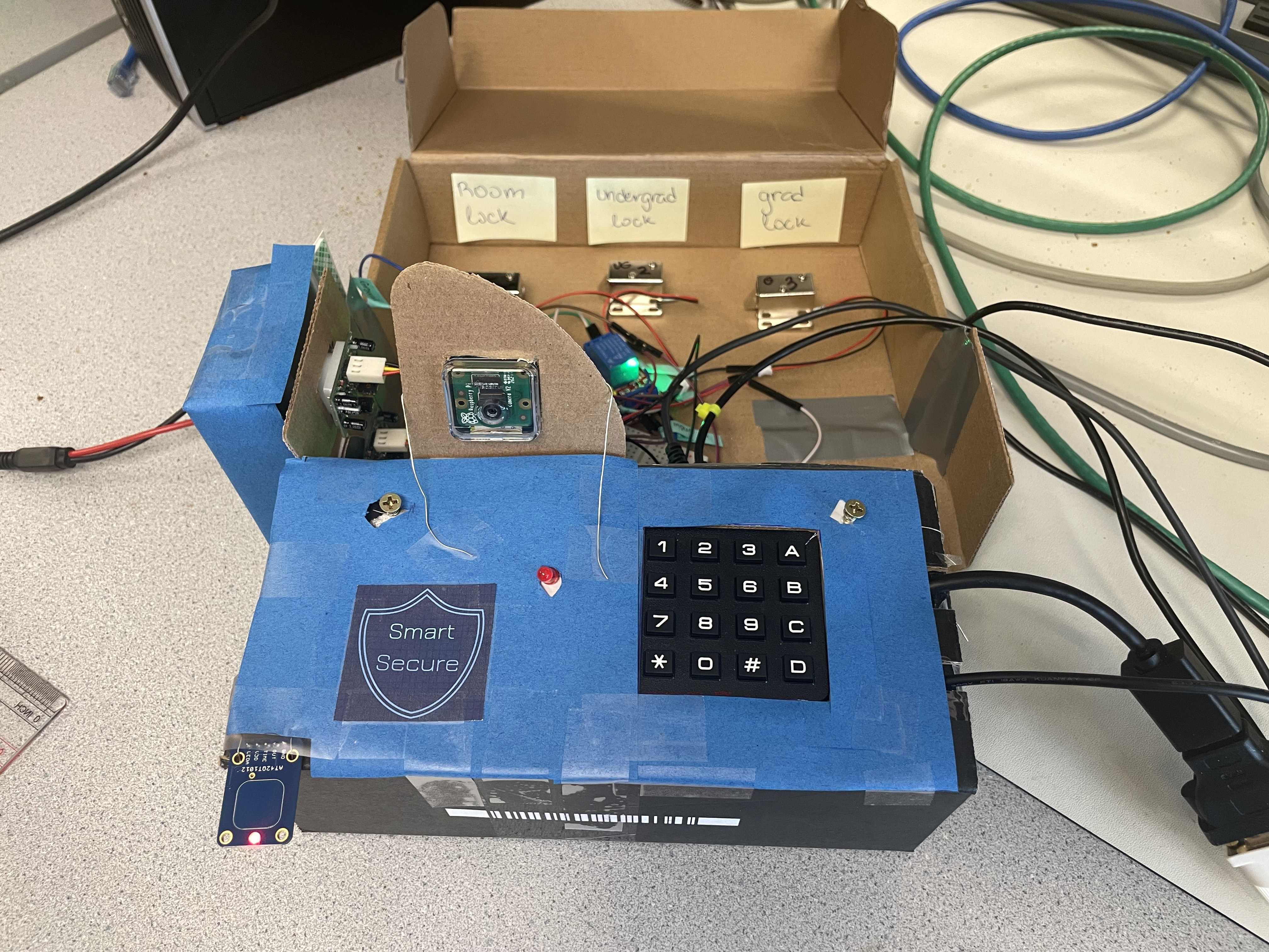
To complete our objective, the system is divided into two main sections: hardware and software. The hardware components include locks with relays to convert small electrical stimuli into larger currents and control the opening and closing of the circuit. They will be unlocked when the user is authenticated with a verified account and correct passcode. Some other hardwares also include multiple pyroelectric sensors for motion detection, a HDMI display for monitor screen, a keypad for passcode input, and a dedicated capacitive touch lock button to arm the security system. Once the lock button is pressed, the security system will be turned on in 30 seconds. The software of this embedded system includes the app and the control codes for the security system. User is authenticated through our app after successfully signing up and logging in. The app will then provide the user with an unique, time-sensitive, 6-digit code to enter the room.
If the passcode is entered correctly, locked cabinets within the lab will be automatically unlocked based on the individual’s pre-set access level. If the passcode is entered incorrectly, the camera will take a photo of the intruder and send a security alert with the photo to the administrator. Individuals with the highest level of access will be able to see the log of all entries to the room on the app. In order to integrate a fully functioning security lock system, we started off with implementing the app, which is written in Swift using XCode and will only work for iOS. All the code that is used to control the hardwares will be written in Python.
Project Objective:
- The objective of this project was creating a smart home security system, an embedded system application that allows different levels of access to the room.
- The system would have to be able to authenticate users through our designed app, which will provide users with a secret, time sensitive code to enter the room after successfully logging in.
- The system is aimed to provide different permissions to users with different access levels. Individuals with the highest level of access will be able to see a log of all entries to the room which includes the login time, user, and their access level on the app.
- With the goal of creating an embedded system in mind, we wanted to integrate all the software with the hardware components to make the process smoothly and legitly.
Hardware Design
Switching from Initial Idea
Our initial idea was creating a smart home system that reports the temperature, humidity, and pressure on the piTFT screen. The current date and holidays will also be displayed in special mode. The problem, however, was that we discovered that it’s impossible to have both the LED matrix panel and the piTFT connected due to insufficient pins on the Raspberry Pi. We instead decided to create an alternative version of the smart home based on our original design. The updated security system would allow for all the necessary sensors to fit onto the pins provided by the Raspberry Pi. The figure below (Fig. 1) shows the concept illustration of our security system.
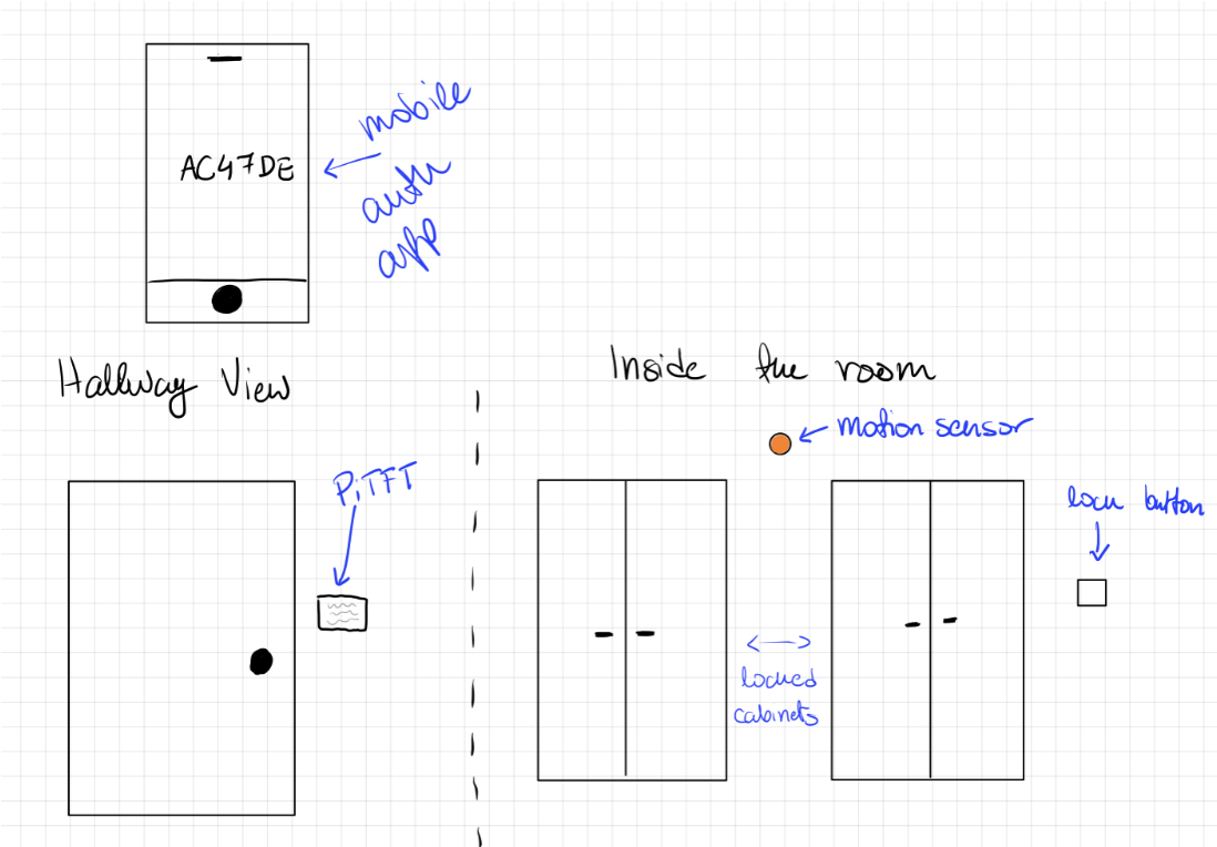
Figure 1. Concept Illustration of Our Security System
The figure below shows our proposed states for PiTFT.
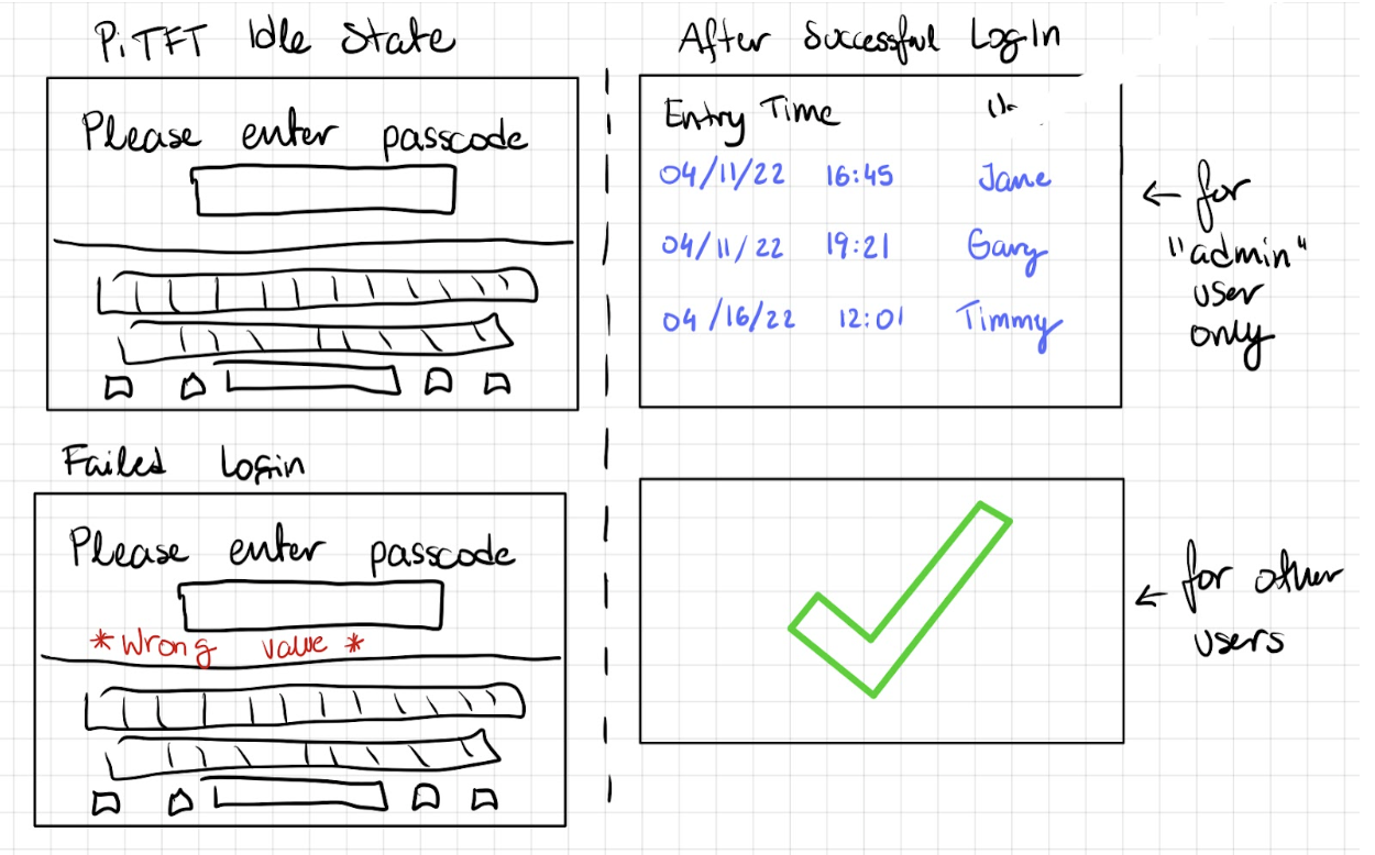
Figure 2. Concept Illustration of Our Proposed States for PiTFT
PIR Sensor
We start off the project by testing for PIR sensors. A PIR sensor has a 3-pin ground/out/power pad, where the rightmost wire is connected to the ground, the middle wire is connected to the Raspberry Pi pin, and the leftmost wire is connected to the power supply (see Fig 3. below).
To set up a PIR sensor, the first step is to set the corresponding pin as input. This can be done through the code GPIO.setup(PIR_pin,GPIO.IN), where PIR_pin is the RPi pin that the sensor is connected to. If the GPIO input for that pin is high, then a motion is detected. This can be checked using the if statement if GPIO.input(PIR_pin).
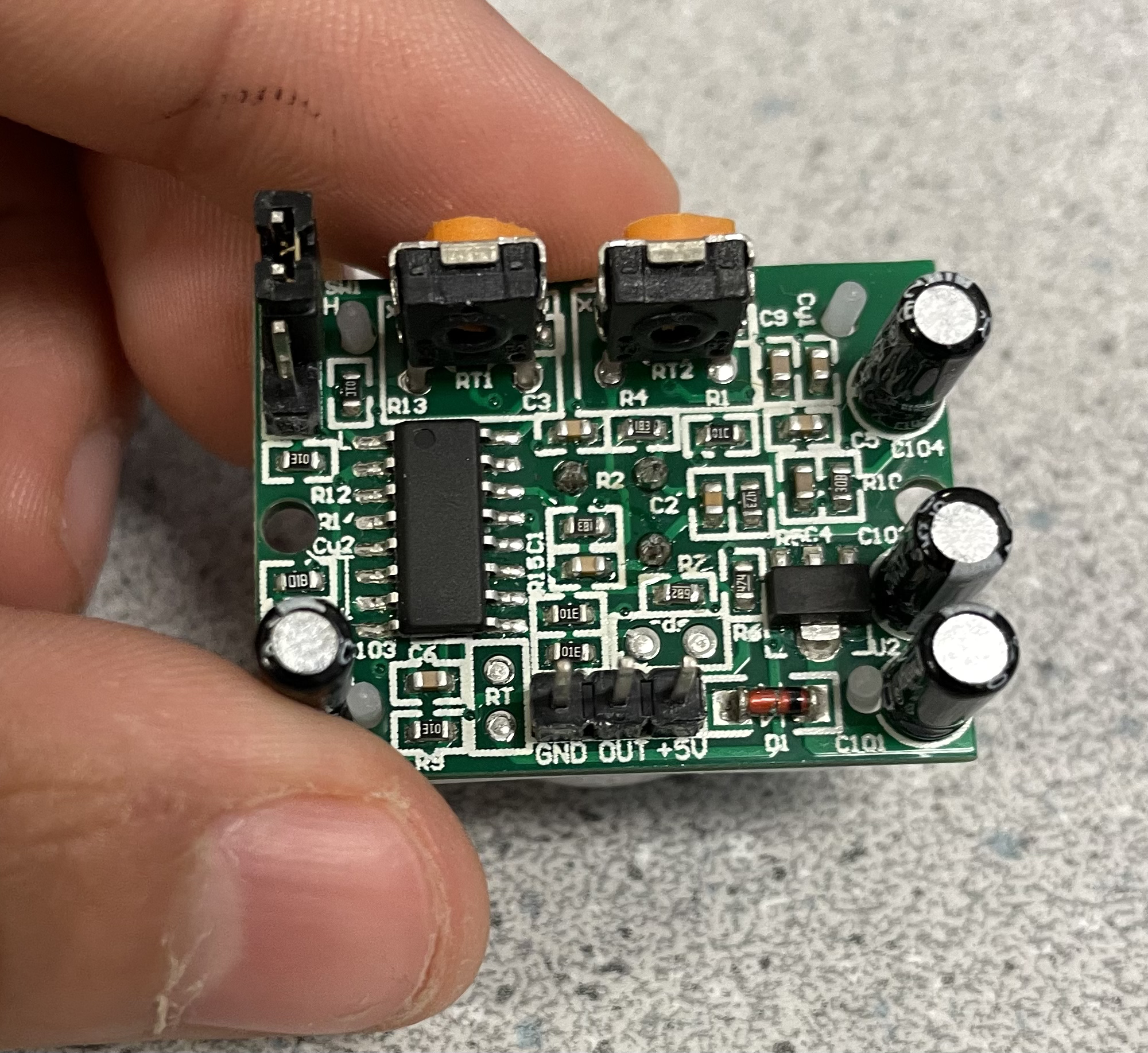
Figure 3. Picture of a PIR Sensor 3-Pin Pad
Matrix Keypad
The 4x4 matrix keypad we are using has 16 built-in push button contacts that are connected to the row and column lines. The RPi can scan through these lines for a button-press event. The keypad has 8 microcontroller pins. Four for indicating columns and four for indicating rows.
To set up a matrix keypad, we start off by setting up the corresponding pins. For the pins that indicate columns, we set them as GPIO inputs using the code GPIO.setup(Cn, GPIO.IN, pull_up_down=GPIO.PUD_DOWN), where Cn is the number of columns. For example, C1 will be the first column. We then set each row as the GPIO output using the code GPIO.setup(R1, GPIO.OUT). After that, we implement a function named readLine(line, characters)that will print out which button is being pressed in each row. Then we implement another function that calls the previous function one time for each row. For example, readLine(R1, ['1', '2', '3', 'A']) handles the first row.
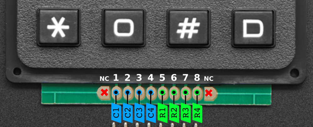
Figure 4. Matrix Keypad Pinout
Source: https://learn.adafruit.com/matrix-keypad/pinouts
Capacitive Touch Button
The mechanism behind the touch button is similar to the PIR sensor, where we set the touch button pin to the RPi pin it’s connected to. The pad is initialized through the function DigitalInOut(pad_pin), and the pad direction is being set through pad.direction = Direction.INPUT. Again, if the pad.value is high, then it is indicating that the button is pressed. This can be done using the if statement if pad.value.
Locks with Relays
Our solenoid locks are controlled by the RPi using relays. A relay is an electrically operated switch. Since solenoids usually require high voltage supply to operate, typically more than 5V, connecting it directly to that voltage would fry the Raspberry Pi because the maximum voltage a RPi can take is 5 Volts. Using relays can prevent this from happening while allowing a passageway for communication. The first step of the hardware setup is connecting the ground pin of the Raspberry Pi to the ground pin on the relay. Then connecting the Vcc volt power to the volt pin on the RPi. The next step is connecting the data pin on the relay to the GPIO pin on RPi. This pin is used to tell the relay either to open or close. Then connecting the solenoid ground wire to the ground connection on the DC power jack. The last step is attaching the solenoid positive to the middle connection on the relay and the positive side of the power jack to the pin on the top of the relay.
The solenoid test works as below. The first step is to assign and set up input pin for locks, which can be done using the code GPIO.setup(LOCK#, GPIO.OUT), where LOCK# is the GPIO pin that the lock is connected to. Use GPIO.output(LOCK#,1) to turn the relay off, because it will bring the voltage to maximum so that GPIO can output ~5V. Use GPIO.output(LOCK#,0) to turn the relay on, because it will bring the voltage to minimum so that GPIO can output ~0V.
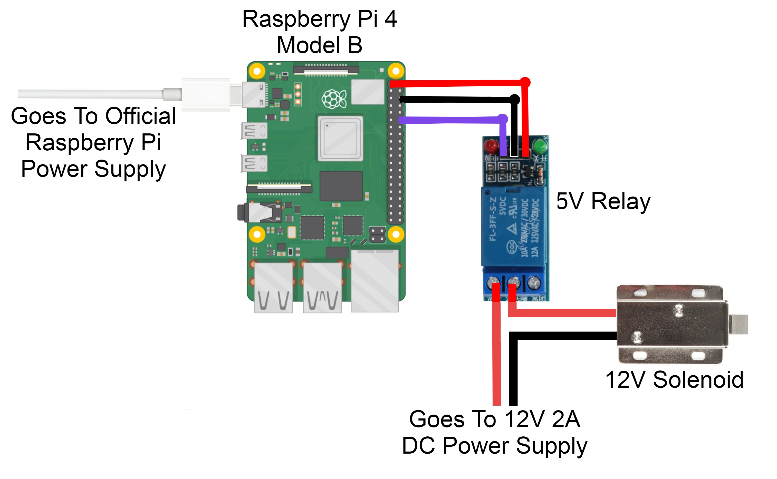
Figure 5. Solenoid-Relay Connection Schematic
Source: https://core-electronics.com.au/guides/solenoid-control-with-raspberry-pi-relay/
LED (Light-emitting Diode)
We initially came up with the idea of implementing a touch button to lock the room, but soon found out a problem: we know that once the button is pressed, the room will be locked in 30 seconds, but how can the users tell if the room is locking down? So we thought LED might be a good choice. However, we then realize that it would be more logically reasonable if there is a stop button for locking down. Therefore, we updated our design so that the room will be automatically locked 30 seconds after correct passcode is entered. The capacitive touch button is used to stop and resume the locking process. Once the button is pressed and the LED is blinking, it means that the countdown is initiated and the room will be lock if it continues blinking for 30 seconds. If the button is pressed again and the LED stops blinking, it means that the countdown is temporarily stopped and the room will not be locked. If the button is pressed one more time and the LED is blinking again, it means that the countdown has been resumed.
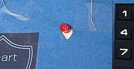
Figure 6. Red LED Light
Camera Module
We also added a camera feature to our security system. Once the PIR sensors detect the intruder, the camera module attached will automatically takes a picture and send it to administrator as part of the message alert.
The setup for is relatively simple. All current models of Raspberry Pi have a port for connecting the Camera Module. After locating the camera module port, we pull up on the edges of the port’s plastic clip and insert the camera module ribbon cable. Making sure that the camera module is fully connected. After that, we enabled the Camera feature under Interfaces in Raspberry Pi Configuration tools and it is all set up.
We did met some issue when connecting the camera module with RPi. It took us many hours of troubleshooting, and the problem is resolved after we changed to a new Raspberry Pi.
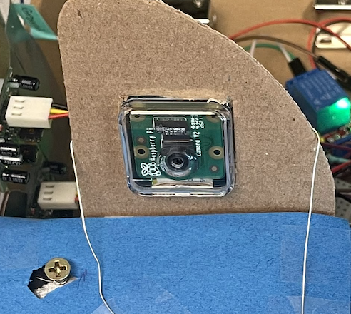
Figure 7. Camera Module
Software Design
While we were working on the project, we realized that the majority part of the system could be divided into and developed as individual modules. We hence separated the components based on their functionality so that we can implement and test them independently for the sake of efficiency.
iOS App
We wrote the iOS App using the Swift language. The easiest approach we found was that due to the amount of user interfacing our app would have, we could simply embed a website into the app. This would allow us to have the greatest freedoms in how the app would look and we were more familiar with web based application development compared to designing a iOS website natively given the timeframe. We used the WebView library that allows us to create a web view once the user opens the app and opens to the login page. On this page the user can either login or click on to the sign up tab where new users can fill out a short form to gain permission to the room. We assumed that the admin user would be the one running the system and would not require a sign up page as they would be the one to select which hardware and permission levels other users would be issued.
If the user enter the passcode incorrectly three times in a row, this person will be temporarily blocked. This means that he or she can neither log into the app nor generaate passcodes. The administrator can unblock them in the App or website by clicking the button "UNLOCK USER" under System Users.
In order to prevent miscellaneous or non-Cornell users from registering and accessing the website, administrator can also delete suspicious user using the "DELETE USER" button under System Users as shown in Figure 11.
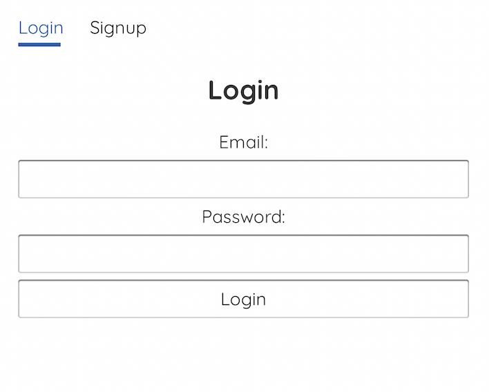
Figure 8. App Screen When Logging In
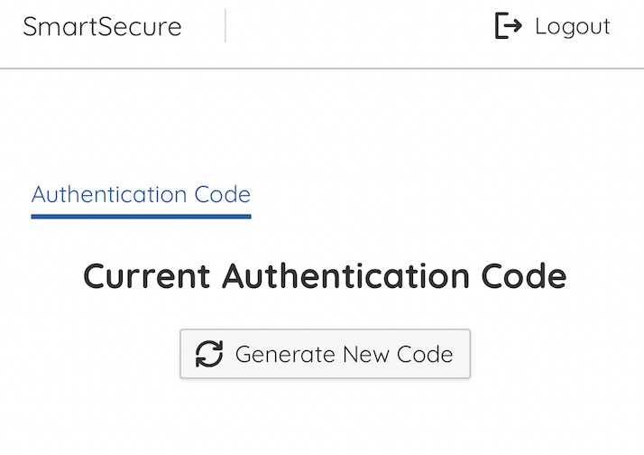
Figure 9. Pressing for New Passcode
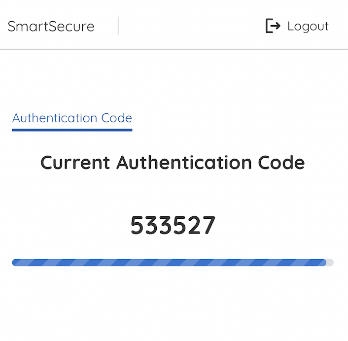
Figure 10. New Passcode Generated, Start Countdown
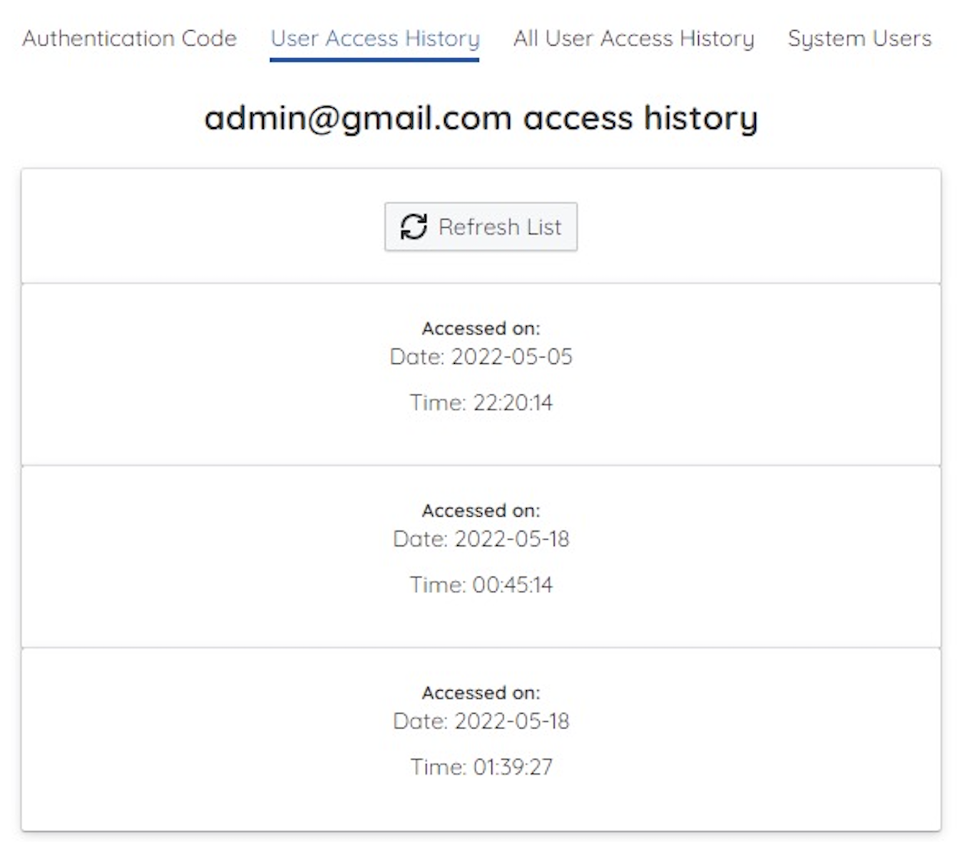
Figure 11. Administrator Can Access User History
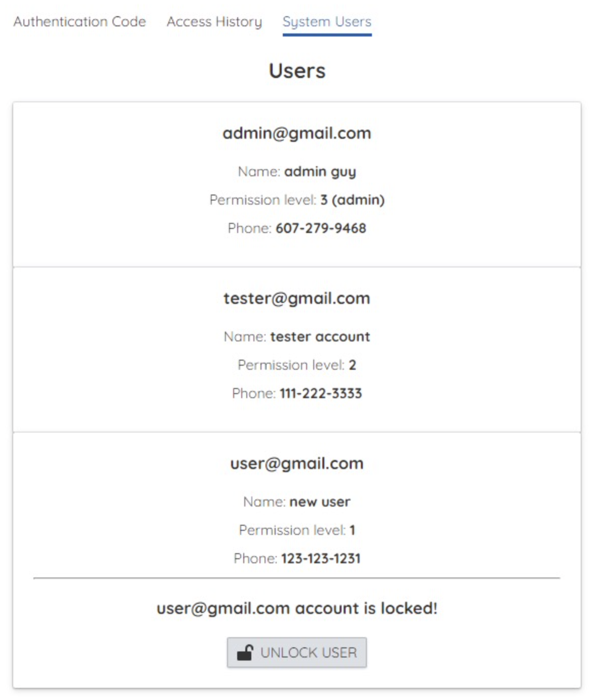
Figure 12. Administrator Can Unblock Blocked User
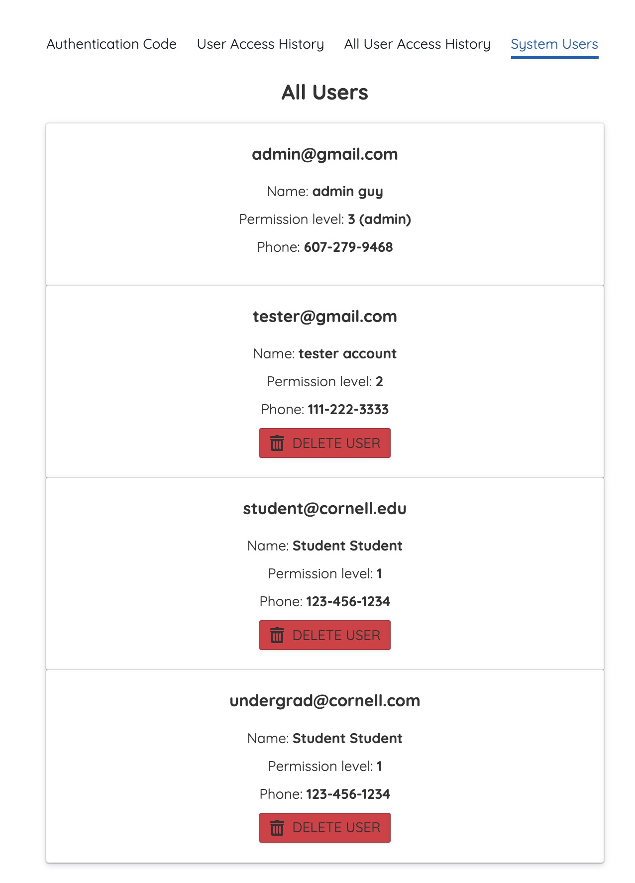
Figure 13. Administrator Prevent Miscellaneous User by Deleting
NodeJS Website and React App
The front end was written in JavaScript and using the React.js library. Using this library allows us to build an effective and efficient web application. The main libraries used in the react app were react, react-router-dom, and axios. React was the main react library that allowed us to use the react app structure and functions. react-dom-router is a library that handles URL routing. Depending on the URL, this library determines where the user will land. Axios was the main library used by the front end application to send REST calls to the express server.
We ran into an issue where REST calls did not go through because the data attached to the requests was not being sent from the front end app to the back end express server. To combat this issue, proxy server was set up using the cors-anywhere github repo which allowed us to transfer data between the front and back end using REST calls. We simply cloned the repo and set up a server using the code, then we appended the server URL of the REST calls with the cors-anywhere heroku address. This made it so that the calls would go through the proxy server to our own server.
Express Server
The backend server that enabled the application to save user data and retrieve user data was written in JavaScript using Express.js and Node.js. Using the Express framework allows us to handle REST calls from the front end and external hardware. The Express server handles user signups and logins, as well as user code storage when the user requests a code in the front end. The external hardware also calls the Express server to retrieve the current code when a code is inputted by a user.
Pygame Display
After the app is fully functioning, we implement the login screen display using pygame. We first initialize the eight keypad pins by assigning them different values based on which GPIO pin it is connected to. We then set column pins using the GPIO.setup(Cn, GPIO.IN, pull_up_down=GPIO.PUD_DOWN), where Cn is the number of columns. Everything else we did to control the keypad is similar to what we did in the keypad testing file.
We then did the pygame initialization. We also implemented a function named check_passcode(usr_passcode) that will check the passcode correctness and set the boolean is_first_time to false. If the user inputs it correctly, the function will return true. Otherwise it will return false. In the while loop, we first clear the screen by filling it black. We draw a rectangle with a white border and no color filled inside as the text input box. Then blit to display it. This can be done using pygame.draw.rect(screen, WHITE, pygame.Rect(left, top, width, height), border_width) and screen.blit(text, textRect), where each parameter is shown below.
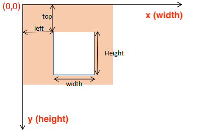
Figure 14. Pygame Screen Coordinate Explaination
If D is pressed, we delete the previous character. This can be done using user_text = user_text[:-1]. If D is not pressed, the keypad will work normally.
If the password entered is incorrect, we display an incorrect message in red using the text_surface = base_font.render(incorrect_msg, True, RED) then blit it. Otherwise, meaning that the password entered is correct, we display a welcome message in green using text_surface = base_font.render(correct_msg, True, GREEN). We also display the user text on screen no matter if the password entered is correct or not. We set the password length to be 6. Once the length of user_text reaches 6, the system will call the check_passcode(user_text) function to check password correctness. If it is correct, we set incorrect_entered to False. Otherwise, we set it to True. At the end, we clear the user_text and flip the screen.
System Security Features Integration
We have implemented many functions in the security_features.py file. To utilize functions we have implemented in other files, we import from textalert import * and from server_communication import *. The following section will provide an overview of all the functions we have implemented in this file:
unlock_room(): This function will get the current user’s level of access by calling function get_permission(). Then call unlock_solenoid(permission_level) to unlock corresponding solenoid locks based on permission level given. This function will not return any parameter.
unlock_solenoid(permission_code): This function will unlock corresponding locks based on permission level. This function will not return any parameter.
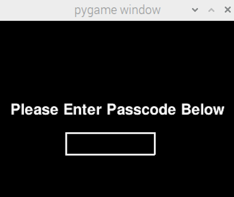
Figure 15. Initial Monitor Screen
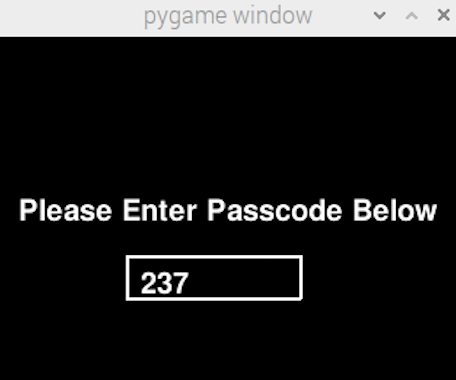
Figure 16. User Input Passcode
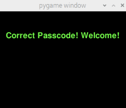
Figure 17. If Passcode is Correct, Display Welcome Message
| Code | Identity | Unlocked Locks |
|---|---|---|
| 1 | Undergraduate | Lock #1, #2 |
| 2 | Graduate | Lock #2, #3 |
| Administrator | Staff | Lock #1, #2, #3 |
lock_solenoid(): This function will lock all three solenoids regardless of whether they're unlocked or not. This function will not return any parameter.
if_motion(): This function will check if either PIR motion sensor has detected anything; if any of them has, the sensor will be set to high and return true. Otherwise, it will be set to low and return false. This function will return a boolean.
capture_photo(): This function will take a photo with the Raspberry Pi camera module and save it on the device. This function will return the image name of the photo taken.
We incorporate this function with textalart.py to send this photo via email or text as an alert.
Testing
When testing our security system, we have encountered various different problems. This section will provide an overview of the testing issues and our proposed solution.
- Camera not working. We had issues with our camera unit initially. The error message keeps saying that the camera is not detected. We solved this problem after discussing with Dr. Skovira by doing a fresh install of raspbian and changing the device to a new RPi.
- PIR sensor not working. We had issues in getting the PIR sensor to work correctly. The PIR sensor lost the connection with the RPi and was not able to detect any motions. We initially thought it’s because the power supply is not enough so we powered it directly with a DC power supply using 9V, a surprisingly large number. The PIR sensor did work, but we soon realized that it is not the root cause. We solved the problem by removing the 10K Ohm resistor that is connected to the PIR sensor and changing it to a 100 Ohm resistor. The problem is happening because we accidentally use a resistor with too high resistance, so the resistor will consume almost all the voltage supplied and the power left to the PIR sensor becomes insufficient.
- Keypad connection. We mistakenly mixed the connection of the first row and the third row so the keypad is printing reversed characters. Luckily, this issue is straightforward and we are able to solve the problem quickly by inspecting the wire connection.
- PiTFT still failed to work. Like always, we again have trouble getting PiTFT to display correctly. Ideally we want the touchscreen functionality on the piTFT to work so that the user can input the password directly on the screen. Unfortunately this didn't work. We then came up with an alternative solution by adding a keypad to replace the touch screen and using a HDMI screen for display only. The solution works out as expected.
- Pygame text input box failed to work. Pygame text input box not displaying correctly, so we removed the input box and replaced it by a text string with a rectangular boundary. This reduced the complexity of the code while retaining the functionality.
Results and Conclusion
Our team did meet the goals outlined in the description and most things are performed as planned except for some minor issues. In order to handle those issues, we have made some modifications on our original plan to make it suitable for the current situation. Overall, we successfully completed the project with all of the functionality of a security system implemented. We also added some extra features to the system to make it look more like a real security system. The app user interface was fully functional and looked just like a real commercial security lock system. The user was able to unlock the solenoid locks with the time-sensitive, 6-digit password generated randomly from the app. The administrator was able to receive an auto-generated alarm notification with a photo of the intruder taken via cell phone. We did exceed our expectations stated in the project proposal. One of the reasons we can successfully achieve the goal is because of the modularity in our design. We separated the work into two modules: hardware and software and worked on both of them simultaneously. Once both implementations were done, we were able to integrate them together and add more features to the prototype. As a conclusion, our game includes the following features. Other features that we didn’t get enough time to implement are discussed in the next section.
- Solenoid locks with relays that will be unlocked when the user is authenticated for room entrance.
- Motion sensors that will check if an intruder has entered the room.
- A dedicated lock button that will lock the room 30 seconds after it has been pressed.
- A keypad that will take inputs for passcode, where character ‘D’ is used for the deleting.
- A camera that will take a photo of the intruder if the passcode is entered incorrectly.
- An algorithm that will guarantee different permission types to each individual based on their pre-set access level, ie level of study.
- An algorithm that will guarantee the system administrators access to the room entry log on the app.
Future Works
Due to the limited scope of this project, we were not able to add all the features we proposed to this project. If we have more time, we would like to refine the design in the following directions:
- Use a 3D printed box. For now, we were using a cardboard box as the outer shell of the system. It satisfied the minimum requirements, but we think it would be better if we could create a container that’s especially designed and better fitted for our security system using computer-aided design and 3D printing.
- Add more solenoids with different levels of access. For now, we only have three access levels: undergraduates, graduates, and administrators. We think it would be helpful to have more levels of access, for example, PhD students and professors so that the system can be potentially more widely used.
- Display the user profile when successfully logging in. For now, only a welcome message is displayed after successfully logging in. We think it would be good to allow the user to upload their profile via the app and display the profile photo on the HDMI display when the user successfully logs in because it provides a more personalized experience when entering the room.
- Add more design to the HDMI display. So that the login screen looks more professional.
- Add a freeze feature to the security system. For now, although alerts will be sent to the administrator, there’s no constraints holding the user to try passcode unlimited times. We think it will be more efficient and safe to add a freeze feature to the security lock system. If the user fails to enter the correct passcode five times in a row or did something that violates the safety rule, the person’s account will be temporarily suspended and he or she needs to contact administrators to get it back.
- Use asterisks or dots to replace the passcode displaying on the HDMI. For now, when entering the passcode, the screen will display the actual 6-digit number. Since the passcode won't expire until a few minutes later, there's a possibility that someone not authenticated will steal a glance of the passcode. Using asterisks to replace the actual numbers of the passcode will prevent safety concerns like this from happening. Note: this idea is highly suggested.
Some other ideas that we discarded include implementing a clear button to clear all characters entered so far on the keypad. We considered it to be not meaningful enough since we have already implemented the delete button. The user can just press the delete button multiple times to clear all characters entered.
Work Distribution
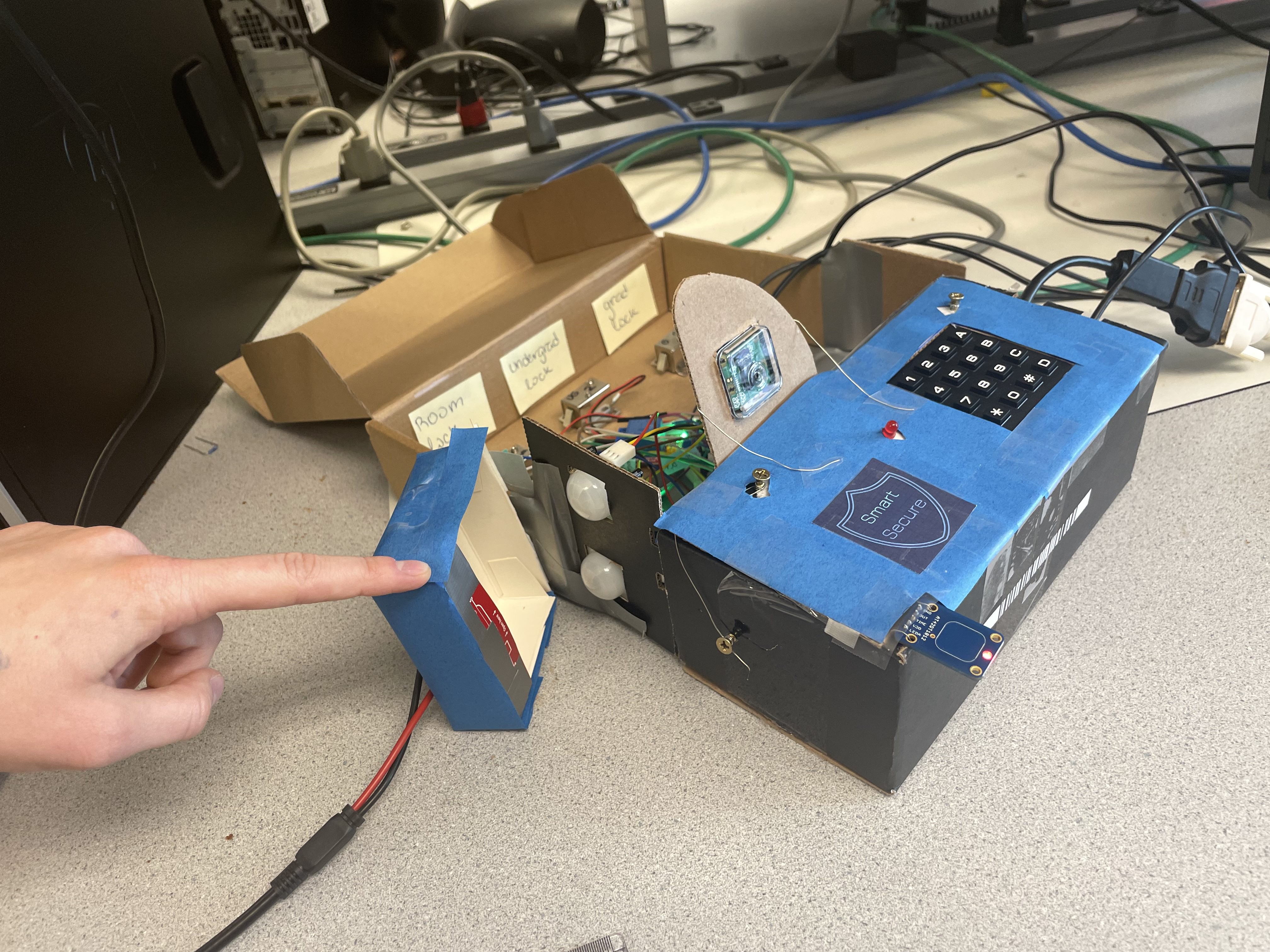
Project Picture Overview

Veronica Gluza
vg253@cornell.edu
Designed the system functionality
Developed the software architecture
Implemented the NodeJS Website, the iOS App, and the backend server

Cindy Wei
yw446@cornell.edu
Integrated the hardware components
Designed and tested the circuit
Handled the project website development and toubleshooting
Parts List
| Item Name | Source Link | Cost |
|---|---|---|
| Toggle Touch Sensor | https://www.adafruit.com/product/1375 | $5.95 |
| RPi Camera Board | https://www.adafruit.com/product/3099 | $29.95 |
| PIR Motion Sensor (x2) | https://www.adafruit.com/product/189 | $17.90 [$8.95 each] |
| Small Lock Solenoid (x3) | https://www.adafruit.com/product/5135 | $22.50 [$7.50 each] |
| 5V Relay (x6) | https://www.amazon.com/dp/B08N6665M3 | $9.99 for 6 |
| 4x4 Matrix Keypad | https://www.adafruit.com/product/3844 | $5.95 |
| Raspberry Pi 4 | Provided in Lab | $0.00 |
Total: $92.24
References
Student Website from Previous Years
We have consulted a few students project sites from previous semesters for website format, smooth transition words, and what context should be included in our final report. We would like to express our thankfulness here:
- CharcuterPi by Kristin Lee and Grace Zhang
- Predator and Prey Handheld Game by Alga Peng and Xiangyi Zhao
- Expirior by Aparajito Saha and Amulya Khurana
Hardware Setup References
| Used For | Source Link |
|---|---|
| Solenoid lock circuit setup with Relays |
A Raspberry Pi Powered Junk Drum Machine
Controlling a Solenoid with Raspberry Pi and a Relay Solenoid Troubleshooting Checklis What Type of Diode to Use to Protect from Short Circuit How to Protect GPIO from Back Currrent |
| PIR sensor connection and programming |
How to Use a PIR Motion Sensor with Raspberry Pi
PIR Motion Sensor: Connecting to a PIR Sensor The Parent Detector Project: Connect the PIR Sensor Raspberry Valley: Connecting the PIR Sensor |
| Camera module setup |
Getting started with the Camera Module
How to fix Raspi camera ‘mmal_vc_component_create: failed to create component ‘vc.ril.camera’ (1:ENOMEM)’ |
| Keypad circuit setup and programming | Matrix Keypad: Overview |
Software Status Configuration Notes
Code Appendix
All codes will be updated separately to Canvas and Github.