ExPiRior
Aparajito Saha and Amulya Khurana
Project Objective
To use embedded systems to build a reliable, automated coronavirus testing platform that minimizes human-to-human interaction at testing sites
Introduction
Technology has always played a crucial role in times of crisis, and the current pandemic has challenged innovation like no other time. In the past year, we have seen several instances of how the pandemic has channeled technological ingenuity like open-source ventilators, 3D printed masks, experimental vaccine methods being brought into production - the list goes on. To add to it, our project “ExPiRior” (derived from the Latin word for “test”) is an autonomous COVID testing site modelled after the coronavirus testing centers at Cornell. It is an embedded system consisting of the Raspberry Pi and a robotic arm that is aimed as a replacement to human presence at the testing sites. Given the rate of transmission and the prevalence of different infectious strains of the virus, we thought it necessary to minimize human-to-human contact to circumvent the rise in infection. Since testing centers face the highest number of potential positives, minimizing the human interaction at these centers by reducing the number of medical staff needed would assist in bringing down the chances of exposure.
In order to replicate the duties performed by the medical personnel in charge of dispensing a test, we started off with a robot arm that would be able to pick up and present a swab and a test tube to the person being tested. As we researched further, we added in additional hardware and software components that would make the system resemble the COVID testing sites at Cornell that we have been accustomed to over the past year, and therefore provide users with a more interactive experience. We integrated messages on the PiTFT display, used a microphone to record user commands and a server to interact with a database of user information and print barcode labels for identification on the test tubes.
System Objectives
Other than an initial startup and for replacement of testing equipment, the system should be able to operate completely independently of human intervention
The system should be able to restore to an initial state after completing each test
The system should not be dependent on an order of individuals to operate
The system display should make it abundantly clear as to the steps the user should follow, and should interact with the user in a manner that allows them to identify errors and issue correcting commands to the system.
Design
While we were working out the details of this project, we realized that each component of the system could be developed as an individual module. We segregated the components based on the function they would perform in order to independently develop and test each component to ensure that it could be usefully applied to support our system’s objectives.
Finite State Machine
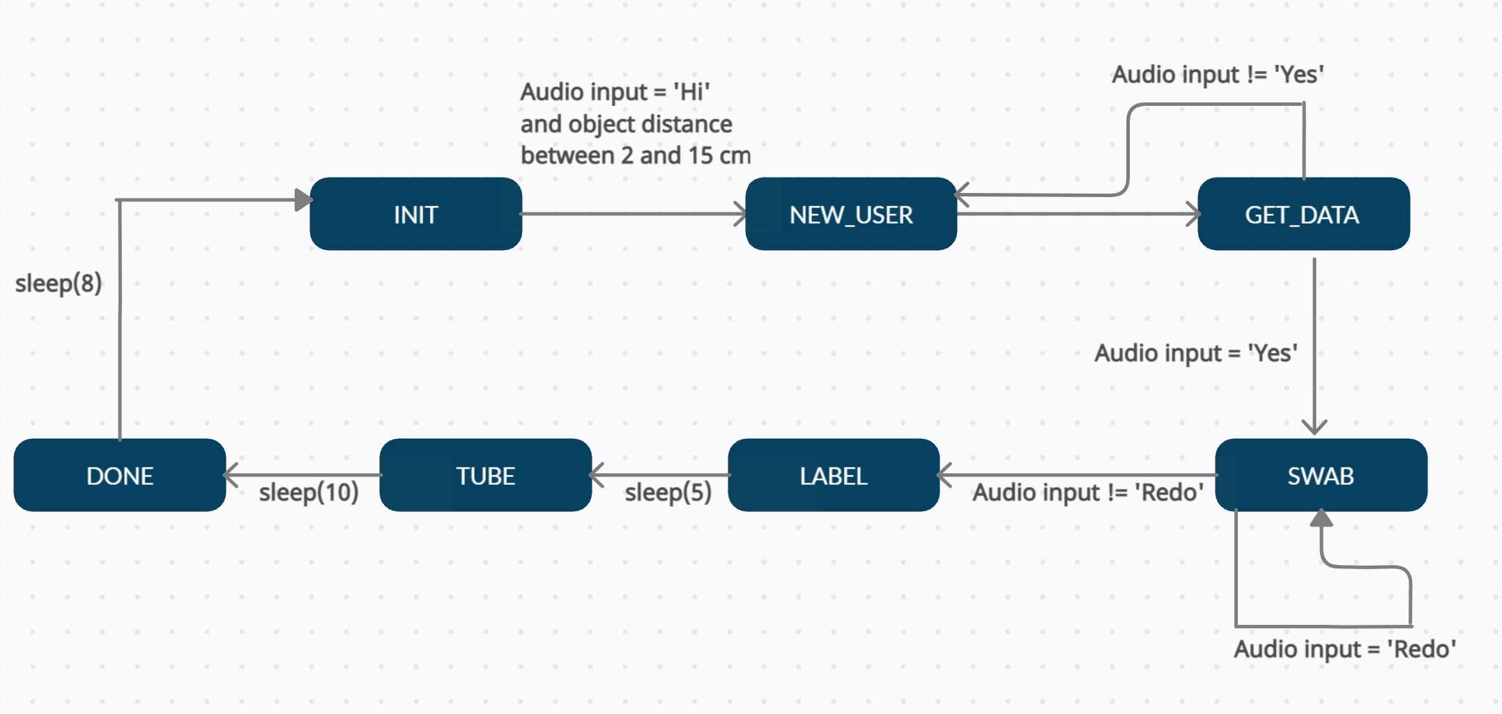
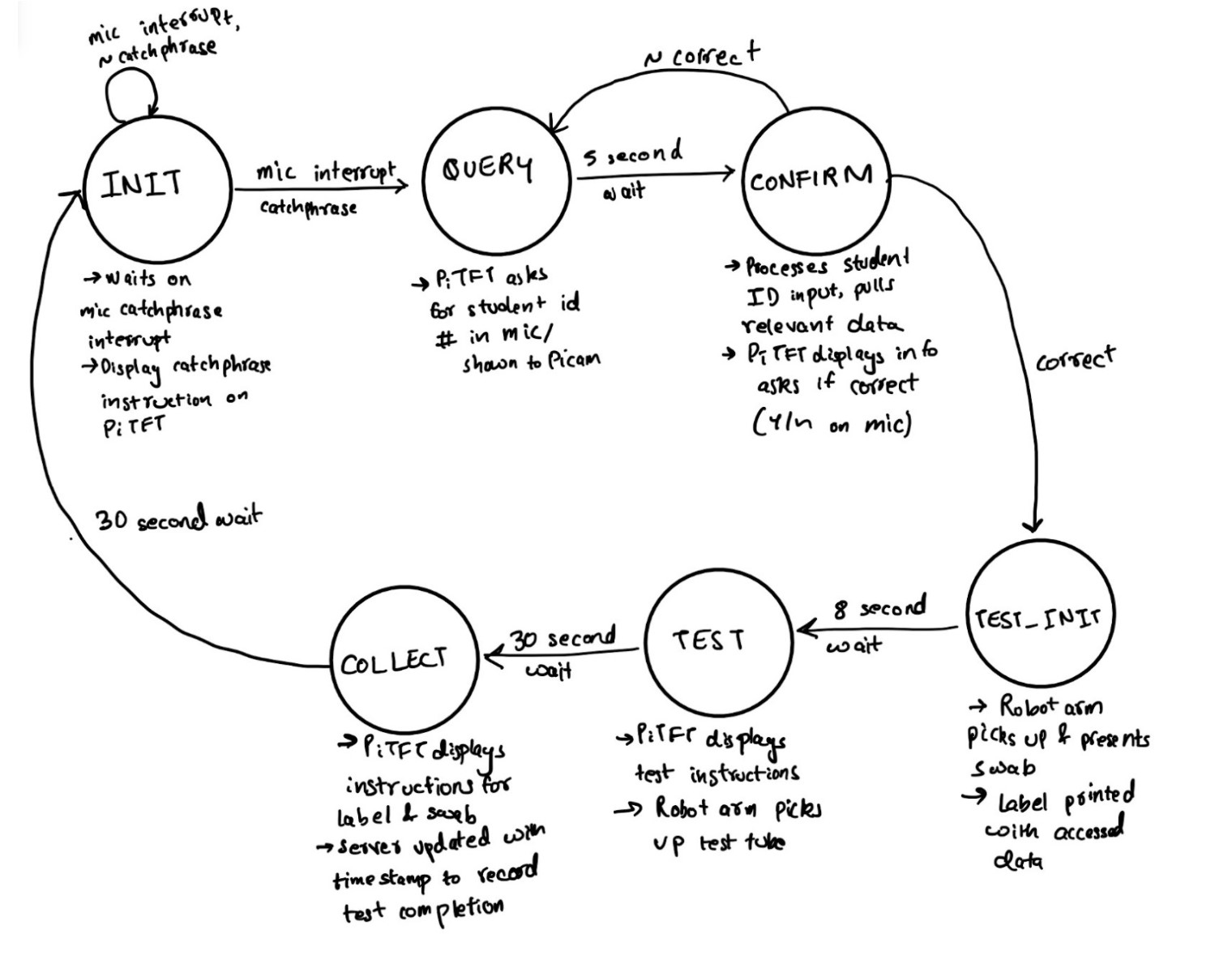
Above is the finite state machine that controls the state of our system and models its sequential behavior triggered by external inputs like audio, ultrasonic detection, etc and a TCP/IP server. The purpose and function of each state is described below:
INIT: This is the initial state that the system goes into by default after a connection with the server is established. The system stays in this state until the ultrasonic sensor detects an object between 2 and 15 cm away from itself and the microphone detects an audio input of ‘Hi’. While the system is idle and in this state, the sensor and microphone continuously poll for input once every clock cycle and the PiTFT displays the message ‘Wave and then say HI to begin'.
NEW_USER: The system goes into this state when the microphone picks up ‘Hi’ and the ultrasonic sensor detects a hand wave over it. In this state, the message ‘Please say your Student ID number into the microphone’ is displayed on the screen. The microphone records the user’s student ID number and sends it to the client over TCP-IP. The system then automatically transitions to the next state after the microphone’s recording period has elapsed.
GET_DATA: In this state, the Raspberry Pi receives the user’s information (netid and date of birth) from the client over TCP-/IP socket communication and displays it on the PiTFT screen along with the message ‘Is this information correct? Please say Yes or No’. If the user says ‘Yes’, this response is sent to the client for label printing and the system transitions to the next state. If the user says anything else, the system goes back to the NEW_USER state where they are asked to say their student ID number again.
SWAB: Once the system is in this state, the robot arm moves to pick up a swab and present it to the user. The following instructions are displayed on the screen for the user to read and follow: ‘Please collect the swab and tear the package. Insert the swab into your nostril until you feel resistance. Rotate it there for 10 seconds. Then switch to the other nostril. Say redo to try again.’ Following this, the user is given the option to say ‘Redo’ in case the robot arm fails to pick up a swab from the container. If the microphone detects ‘Redo’, the system loops back to the same state so that the arm can try again. If not, the system transitions into the next state.
LABEL: This state is simply a reminder for the user to switch nostrils. The message ‘Please switch to the other nostril.’ is displayed on the screen. In the meantime, the client on the computer is sending a print command to the label printer to print a barcode label with the user’s information. Five seconds later, the system automatically moves into the next state.
TUBE: This state displays instructions for the user to complete their test. The massage ‘Place the swab in the test tube. Collect the label and paste it on the test tube. Then place the test tube in the tray to the left.’ is displayed on the screen. Ten seconds later, the system automatically moves into the next state.
DONE: This is the final state of the system where ‘Thank You’ is displayed. The test is completed at this point and the system will go back to the INIT state after 8 seconds.
We used PyGame, a python package that makes it simple to create text surfaces to be displayed directly on the screen, to display instructions for the user on the PiTFT. We created text surfaces and the corresponding rectangles for each line of text and then blit them onto the screen according to the current state in the finite state machine. This is similar to how we displayed data and images on the PiTFT in the labs.
MeArm Robot Arm
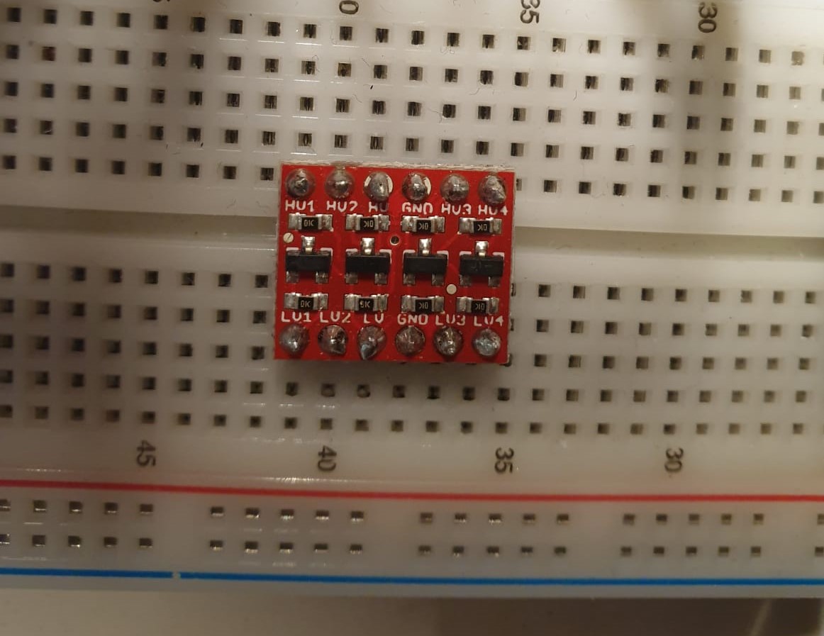
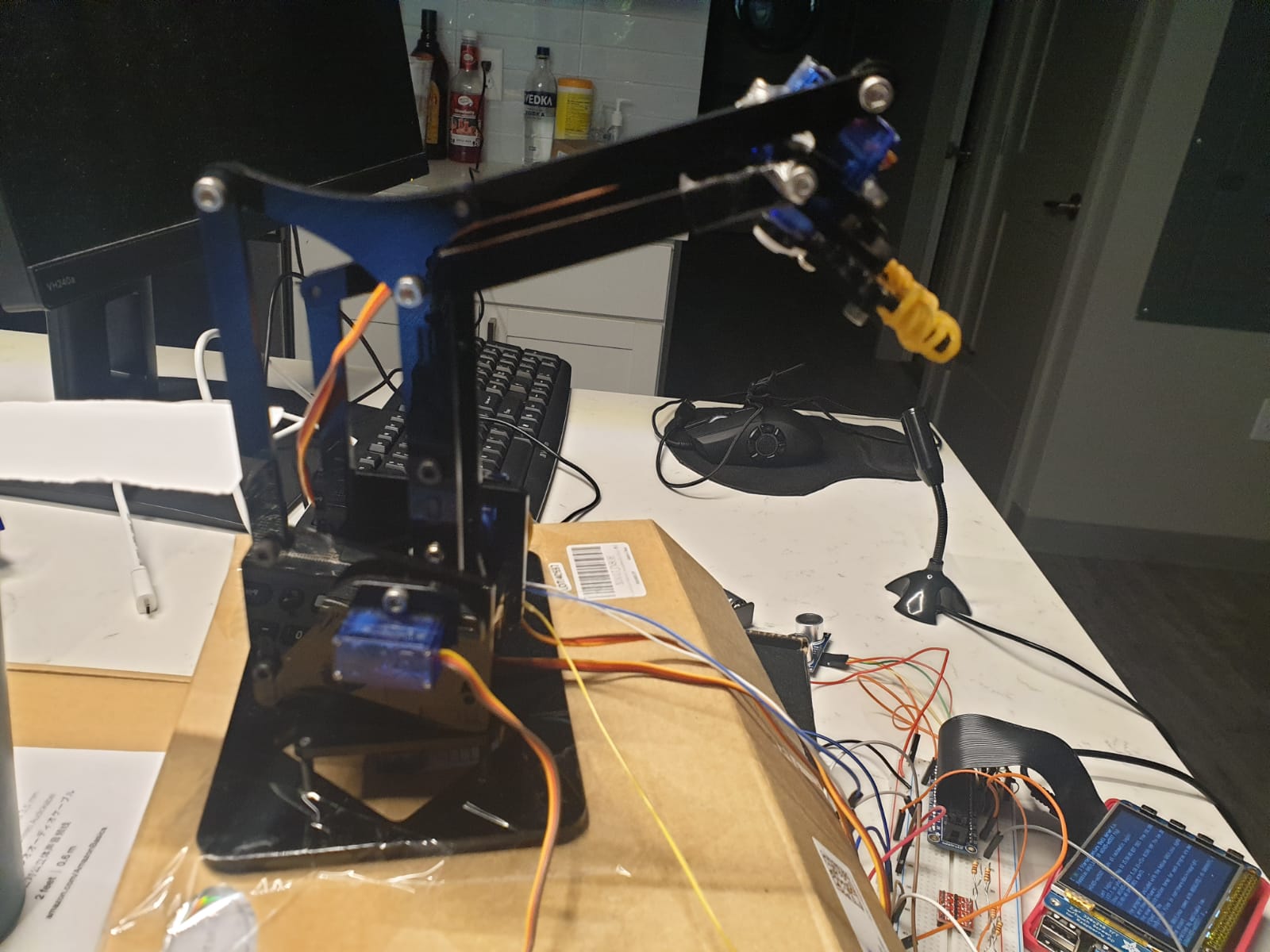
The MeArm robot arm consists of four SG-90 servos - one to control the movement of the claw, one for base rotation, and two to control the movement of the elbow (forward/backward and up/down). Each servo has three wires, one for ground, one for the power supply, and one for logic control. Documentation states that the PWM period for the servo is 20 ms so it operates at a 50 Hz frequency, and that the servo has a voltage rating of 4.8 to 6V. We used a battery pack to supply 6V of power and a logic converter to change the 3.3V output logic from the Pi to 6V for controlling the motor PWM. The datasheet specifies the pulse for three different positions - position “0” (1.5 ms pulse) is the middle, position “90” (2 ms pulse) is the right, position “-90” (1 ms pulse) is the left. Following this, we calibrated the servos individually to record their middle, right, and left positions using the ChangeDutyCycle function to manipulate their duty cycles. We wrote a test program to coordinate the servos to move in a particular direction. However, we realized that this caused accumulation of errors leading to unintended movements when the arm had been running for a while. Research to overcome this problem revealed a Python library called gpiozero that makes physical computing with Python easier and more reliable across a number of peripheral devices including the “Servo” module. This library has three built-in functions: min(), max(), and mid() to move the servos to the three positions described above. After calibrating the servos with these three functions, we were able to write values between -1 (min) and 1 (max) to move them to a particular extent. For example, writing a value of 0.7 opened the claw just enough to grab a test tube. Moving the base rotation servo between it’s min and max positions rotated the arm between the swabs and the user. Using this library, we wrote a function to move the arm such that it moves towards the swabs container, picks up a swab, moves towards the user, and releases it.
Microphone
We followed the Google Developers guide to configure the microphone to be used with the Raspberry Pi. Since the Raspberry Pi does not have any analog inputs, we had to use a USB microphone to detect ambient sound and convert them to a digital format usable by the Pi. For device recognition, we first updated the operating system by running sudo apt update and sudo apt upgrade. Then running the command arecord -l listed the capture hardware devices and told us that the microphone was identified as device 0, card 1 by the RPi. Using this information, we created a hidden configuration file called .asoundrc with the device and card number. Following this setup, Raspian was able to read the configuration file and detect the microphone as soon as it was plugged into the RPi. Then, using the arecord command we were able to record wav audio files that would be used for speech recognition - since we were expecting audio clips only a few seconds long, we thought that recording the input from the microphone would be more efficient than attempting to process the sound in real time. We used the SpeechRecognition python library to decipher the audio files. This was very simple to use with the record() function to load audio into memory and the recognize_google() function to convert the speech to text. This method requires a connection to the internet since it uses Google Cloud Speech API to decode the audio file.
Ultrasonic Sensor
We tested our state machine several times and realized that the microphone was very sensitive to sound and unintentionally triggered the testing process when someone at a farther distance said ‘Hi’. This was a problem since a COVID testing center has several testing booths in close proximity and a test may be falsely triggered in the case that the microphone picks up input from another booth. To overcome this problem, we added distance detection so that a test begins only when the user waves over the sensor. The HC-SR04 sensor is an ultrasonic distance sensor that senses object proximity using ultrasonic reflection. It has four pins - GND and VCC connected to ground and the power supply respectively, the Trigger Pulse Input pin that triggers the sensor to send an ultrasonic pulse, and the Echo Pulse Output pin that is set high for the duration of the echo pulse from an object. Following the PiHut reference, we connected the sensor pins to the RPi as shown in the schematic below (Source: PiHut):

We set up the TRIG and ECHO pins as GPIO output and input respectively, set the TRIG pin low, and gave the sensor two seconds to settle. To trigger the sensor with the required 10 microsecond pulse, we set the TRIG pin high and added a 10 microsecond delay before setting it low again. Next, we measured the length of the pulse from the time the ECHO pin is set high. The distance is then calculated using the speed formula with the speed of sound (343 m/s). After testing a couple of times, we decided to set the range of detection between 2 and 15 cm. This means that if an object (the user’s hand in our case) is detected at a distance of between 2 and 15 cm, the testing process begins.
TCP/IP Server
To manage the memory and processing resources, we chose to avoid storing the database of students appearing at the testing center on the Raspberry Pi and set up a socket communication protocol between the Pi and a laptop that acted as a “server” storing student information. We chose the TCP/IP communication protocol since it allowed us to interact between the two computing systems data wirelessly and send and receive all data packets in order.
As elaborated in the following section, we chose to establish the Raspberry Pi as the server and the laptop with the student information database as the client. We configure the server to be able to send string messages and receive encoded data from the client depending on the studentID being sent. We use blocking protocols to ensure that the connection from the client can be accepted whenever the client is initialized so that there are no synchronization errors that prevent the client from working. After the initial handshake is complete, we encode the student ID spoken into the microphone and transmit it over the designated IP port to the client for authentication and extraction of the corresponding netID and date of birth for the tester. This data is then encoded and transmitted to the Raspberry Pi, which polls the connection port until it receives the data.
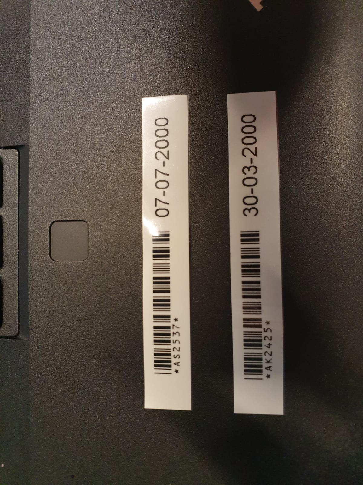
Depending on the integrity of the information as verified by the user, the Raspberry Pi sends the laptop client a message to print the label for the test tube via the label printer. We initially wanted to use this label printer alongside the Raspberry Pi, but due to the unavailability of the correct drivers for the computing architecture of the Pi, we improvised and used the label printer connected to a Windows laptop. We installed the editor that permitted us to generate labels and found that this editor could be connected to a database and could be manipulated by keyboard shortcuts for printing. We used the client API that we had established to run a script that manipulated the printer editor to access the entries from the database, create a label with a barcode and date of birth and send a print command over USB to the printer. Once the client connection with the server was established, this script was run as part of the communication process of student ID and data confirmation.
With all these parts of our design established and tested, we could successfully replicate the COVID-19 testing center at Cornell.
Testing
Since our design focused on implementing modular segments for all the software and hardware aspects of our project, we were able to rigorously test and improve our initial framework before integrating all the elements of the project together. Below, we list the components making up our system, and the system design implications they had.
Microphone
Initially, we intended to record netIDs for identifying the person using the system to conduct a coronavirus test. With extensive testing of the microphone in different circumstances, we found that the microphone can only distinguish the letters of the netID clearly when the surroundings are quiet and each letter is clearly enunciated. We did find that numbers were always correctly predicted by the speech recognition API in Python, which led us to change over to using our unique student IDs instead. We also discovered that the speech recognition API could distinguish between ambient noise and human speech really well, but could pick up human speech not explicitly directed towards the microphone too - to circumvent errors that this might cause, we added in the ultrasonic sensor to confirm human presence at the testing station before validating the microphone’s initial input and starting up the system.
MeArm Robot Arm
We carried out a significant amount of testing to determine the MeArm Pi’s capabilities. Since the arm was preassembled and had been used for other purposes before being used in our project, we needed to initialize and check the calibration of the SG-90 servos before attempting to determine the range of motion required to drive the arm to pick up the swabs and the test tubes. We started by using the RPi.GPIO library to calibrate the PWM signals being sent to servo on the arm, but quickly found that three of the servos did not PWM signals as intended, while the fourth did not work at all. On further inspection, we realized that one of the servos was completely damaged and needed to be replaced in order to carry out the desired arm motion. With the replaced servo, we tested the arm further with the GPIO library, but found that writing PWM signals from the “hardware” PWM pins on the Raspberry Pi caused the screen on the piTFT to flicker. We proceeded to search for libraries that would enable us to write PWM signals from any pin using software emulation. We found two principal alternatives - gpiozero and piservoctl. While we managed to use piservoctl to some degree of moderate success, we found that gpiozero could define a Servo object that was optimized for writing PWM signals to the motor, and could reliably control three out of the four motors to do the actions we desired.
Using this library, we were easily able to pick up swabs from a designated container and maneuver the arm to turn 180 degrees and present them to a user. However, we found that the “elbow” joint on the arm was unable to deliver enough torque to pick up the sample test tube from its holder and present it to the user, even though it could move once it had the test tube contained in its claw. We evaluated a number of different approaches for the end effector to make it adhere to the test tube better, and attempted to change the holder for the test tubes to make it easier for the tubes to slide out. Unfortunately, we had no success with these options, and short of replacing the entire arm for a system with better servos, it was not possible to come up with a better solution in the stipulated time. We chose to place the open test tubes right next to the label printer so that the robot arm could present the user with only the swab and the user could put the swab after sample collection into the open test tube before sticking the label onto the test tube.
Server communication
While organizing the handshake code for the TCP/IP server-client communication protocol was fairly simple, effort was needed in order to debug communication problems as well as meaningful command execution. We initially had some trouble using the laptop as the server and the Raspberry Pi as the client as Windows firewalls prevented us from keeping a socket open for wireless connections for extremely long durations. We decided to change the socket mechanism and instead make the Raspberry Pi the active server with the laptop behaving as a client that could respond to the Pi’s commands. We found that using string to byte encoding improved the transmission time and integrity, and we allocated a transmission and receival buffer size of 4096 bytes to allow data to be received in a single packet.
Results and Conclusions
We managed to surpass the expectations stated in our original project proposal for this idea. Our modular design and testing approach was the key to us realizing this goal - we iteratively developed updates to our initial concept that allowed us to achieve our final system. Aspects such as the student ID processing, ultrasonic sensor verification and complex server-client interaction for label printing were developed by considering the initial purpose behind their simpler implementations and researching how the design could be made robust. However, there were some components that did not work as expected. Most importantly, the servos on the robot arm were too weak to be programmed reliably and after several hours of testing and debugging, we chose to eliminate that aspect of our project and instead had the user place the swab in a test tube themselves. We were still able to carry out a successful demonstration as shown in the project video, and even tested use cases such as multiple COVID tests being delivered sequentially and incorrect student IDs being spoken and processed, and ensured that our system was robust enough to contend with these problems.
In general, we believe that this autonomous testing site can be implemented widely at testing centers and effectively minimize human contact as well as staff required. The only manual labor required is to place the test tubes and swabs at the beginning of the day and collect the samples at the end of the day. All components of the system work reliably without any errors and can be trusted to administer a COVID test correctly.
Future Work
There is a lot of scope for extending this project and scaling it for use at COVID testing centers across the world, especially with the virus resurging in parts of the world. A stronger and more stable robot arm can be used to effectively pick up and present a test tube to the person being tested. This can be simply implemented using the existing arm code with the gpiozero library. Further, beam break sensors can be used to identify errors in arm movement and direct the arm to the correct location to pick up a test tube. DYMO label printers have drivers that make them compatible with the Raspberry Pi. Using such a printer would make printing labels directly and wirelessly from the RPi possible. For more integrity, a camera can be used to identify a user and confirm that it is not a false test. The project can also use actual servers to store user data instead of a laptop. Our entire design accounts for the possibility of expanding further and hence is easily adaptable to similar projects.
Pictures
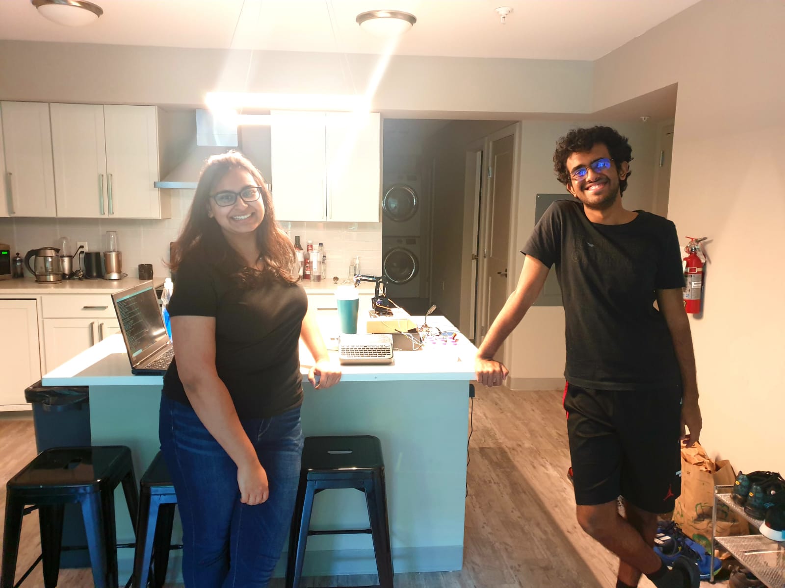
The Team
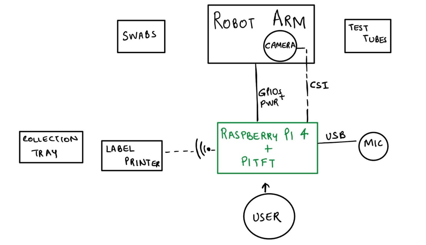
Proposed System Layout
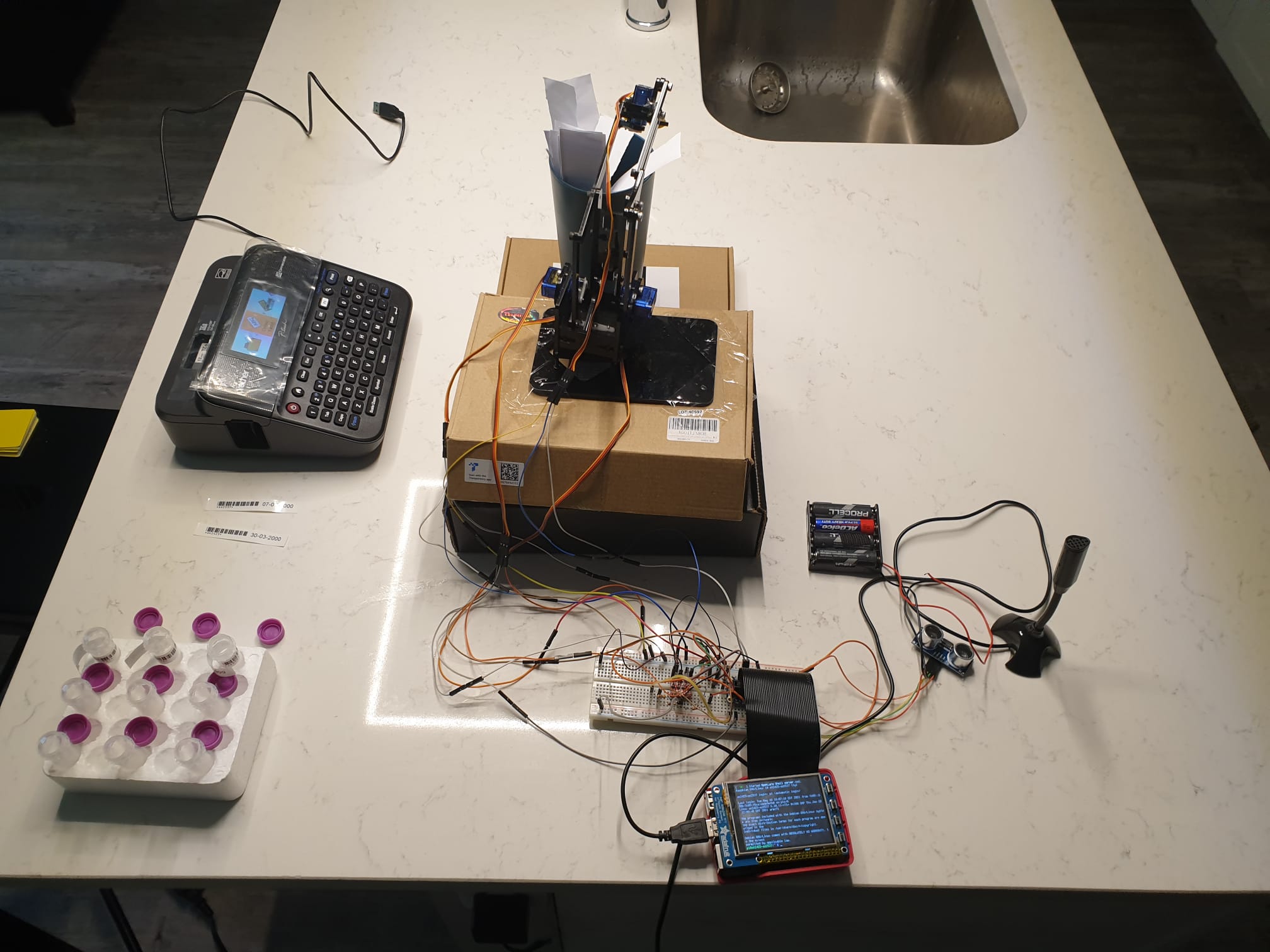
Actual Physical System Layout
Proposed Finite State Machine
Final Finite State Machine

Voltage Level Converter
Robot Arm
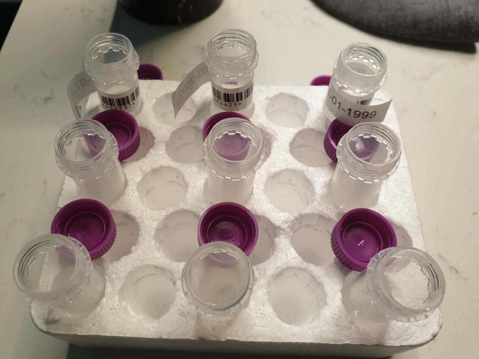
Barcode Labels
Test Tubes with Barcode Labels
Budget
Raspberry Pi 4B (2GB RAM) - $30
PiTFT - $30
5V Power adapter - $5
16 GByte SD Card - $4
Raspberry Pi Case - $4
HC-SR04 sensor - $1.60
Brother P-Touch Label Maker PTD600 - $90
MeArm Robot Arm - $23
USB microphone - $9
4 AA batteries - $4
We borrowed all parts from the Professor Skovira’s lab and the Cornell Maker Space. We did not have any expenditure of our own in this project.
References
Speech recognition using PyPi
Setting up the MeArm Robot Arm
Using PiServoCtl for servo control on the robot arm
Using gpiozero for servo control on the robot arm
Recording and playing audio files on the Raspberry Pi
Using the HC-SR04 sensor with the Raspberry Pi
Keyboard manipulation using PyAutoGui
SG90 servo datasheet
Using a microphone with a Raspberry Pi
Code Appendix
Full code hosted on GitHub: https://github.com/AparajitoSaha/ExPiRior
Contact
Project by Aparajito Saha (as2537@cornell.edu) and Amulya Khurana (ak2425@cornell.edu) for ECE 5725