Hardware Design
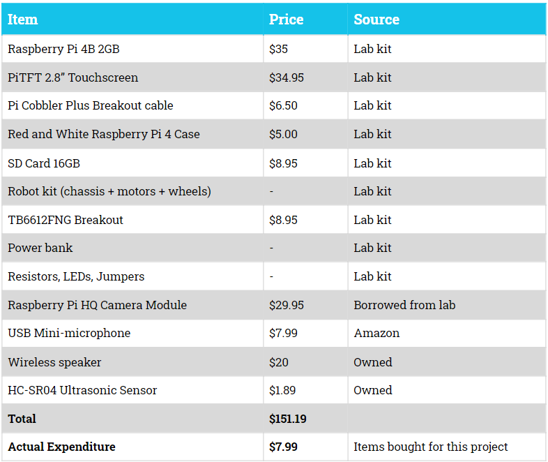
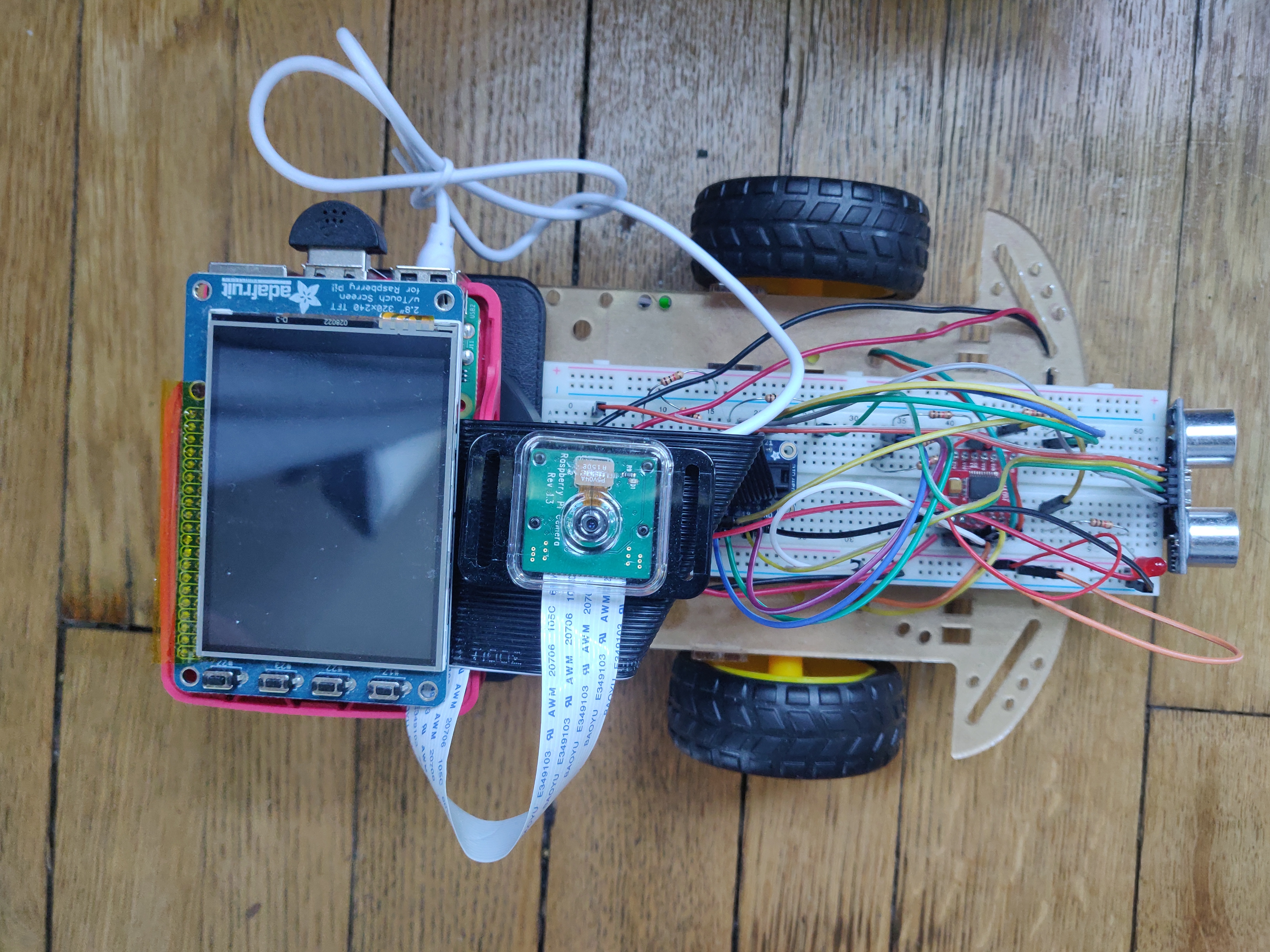
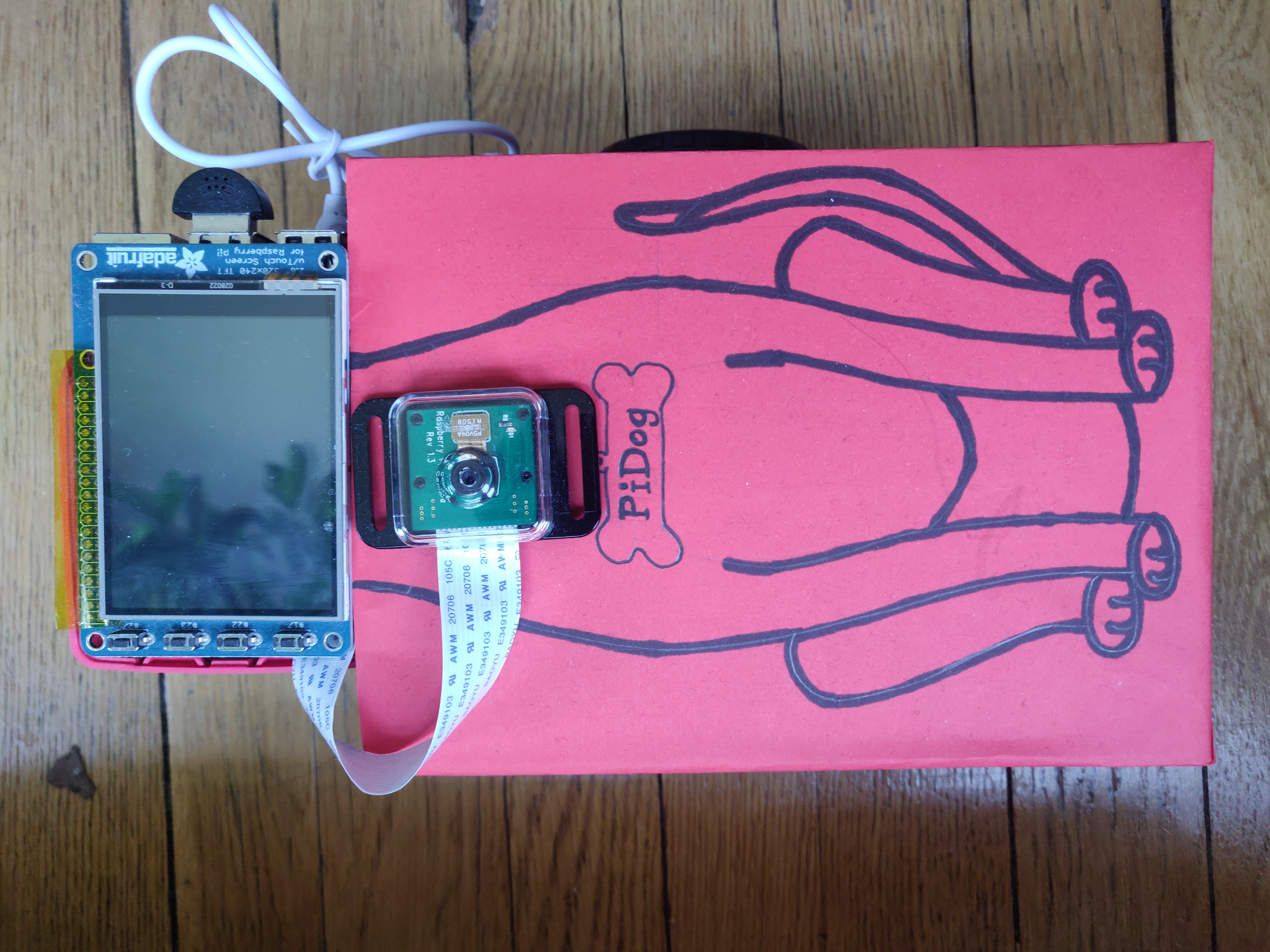
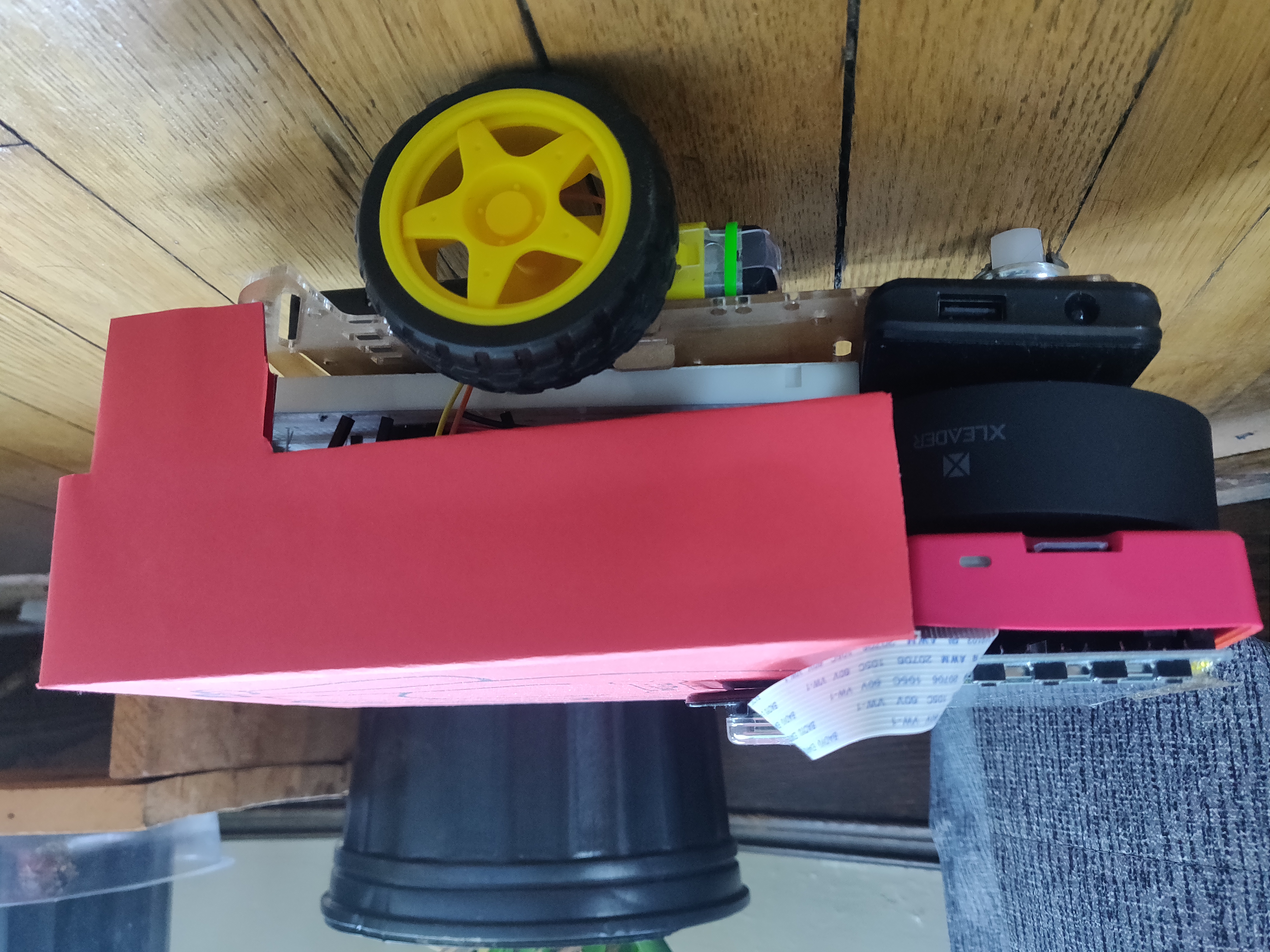
The physical design of PiDog is a two-wheeled robot with a Raspberry Pi with PiTFT screen mounted on top. For this, we adopted the robot kit we used in Lab 3 and built on top of it to add other components. The robot broadly consists of the following parts: Raspberry Pi + PiTFT, breadboard circuit with motor driver, HC-SR04 Ultrasonic sensor, Raspberry Pi HQ Camera, USB microphone, portable speaker, power bank, robot chassis + wheels. The basic robot was the same as in Lab 3, which used the TB6612FNG motor driver IC connected to +6V power and two DC geared motors. The motor driver was connected to GPIO pins on the Raspberry Pi, which were manipulated with PWM to run the motors. We used the ultrasonic sensor to detect any obstacles in front of the robot, and was therefore mounted on the very front edge with the help of velcro. The HC-SR04 sensor consists of four pins, two for power and TRIG and ECHO, which were connected as GPIO. Since this sensor operates at 5V, we used a voltage divider circuit to drop down the voltage level to 3.3V for the Raspberry Pi. The USB mini-microphone was connected directly to a USB port on the Raspberry Pi, and was used for speech recognition of voice commands. The installation of the camera required some design considerations. We had initially planned to have it face forward, such that it detects hand gestures done in front of the robot. However, the way the hand detection algorithm was designed, it needed a static background against which the hand was compared. Since the robot is mobile and would face different surroundings at different times, we decided to mount the camera facing straight up in order to keep the ceiling as a pseudo-static background. This was also biomechanically better as interacting with the robot so low on the ground would have been strenuous. Now, however, we needed to ensure that the camera faces exactly up, otherwise it might also detect the body of the user while doing the hand gesture. (See Software Implementation: Hand Detector) This camera was connected to the camera port on the Raspberry Pi and placed on top of a platform to face up. Finally, the portable speaker was used to play a barking sound, and connected to the AUX port on the Raspberry Pi. The Pi and all these components (except motors) were powered by the power bank. For aesthetic purposes and as the platform for the camera, we created a cardboard shell over the robot that also serves as the body of PiDog!

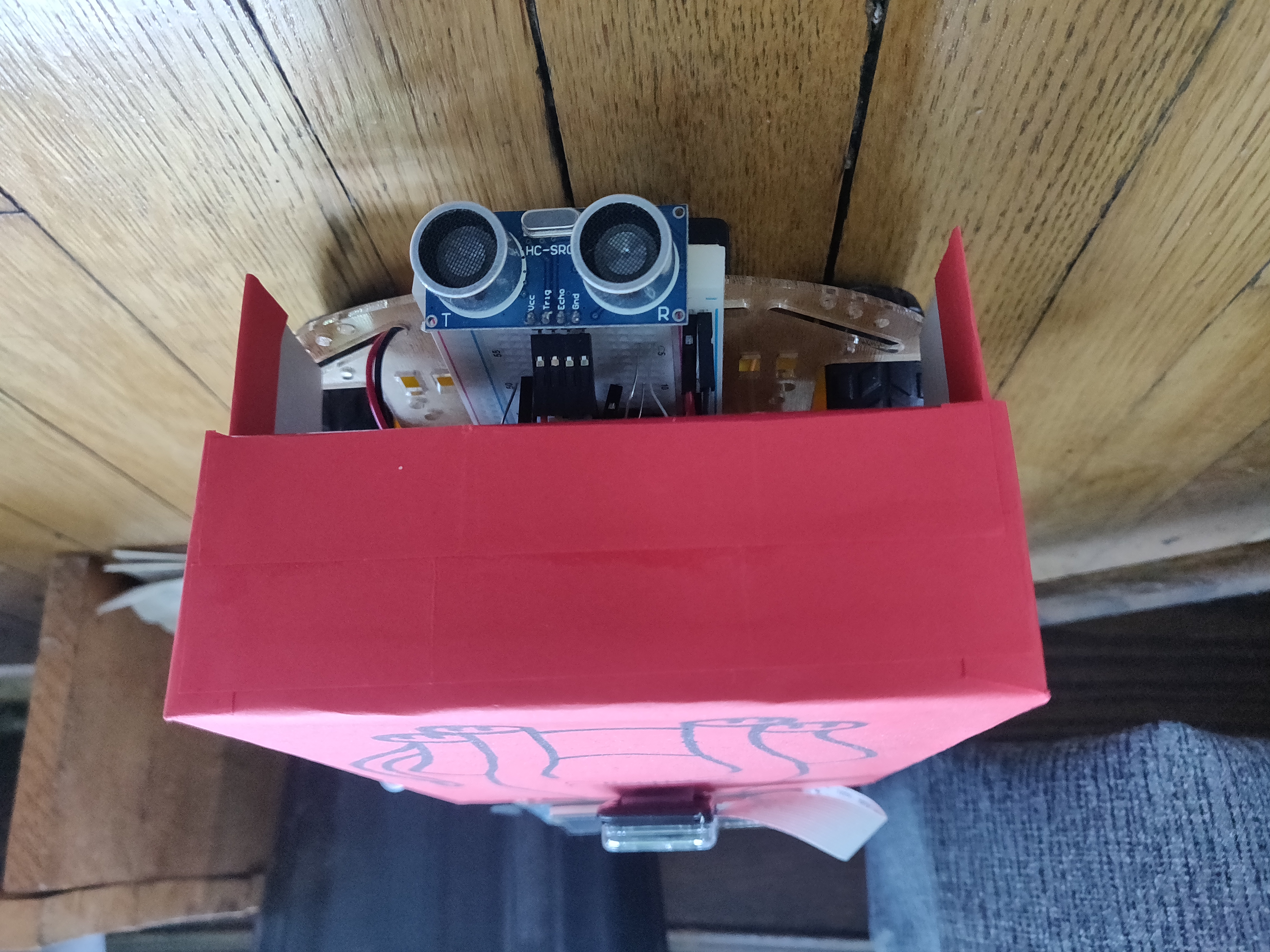
Budget