Making Our Own ROM
While designing the emulator, we realized that there is a limited number of Chip 8 ROMs that are freely available online. In order to improve the variety of games that one can play on our arcade game console, we decided to make our very own Chip 8 ROM. This was a very challenging task for us to complete because we have little experience in ROM editing, much less creating ROMs from scratch. However, we were determined to create our very own ROM to further customize our arcade game and set it apart from other retro arcade games.
What is a ROM?
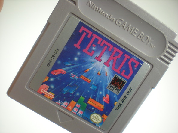
Some of us might be wondering what exactly is a ROM? Well, a ROM is simply a storage chip that consists of Read-Only-Memory, hence obtaining its name as ROM. Data stored in these ROMs can only be read, as the name suggests. Some examples of ROMs include game cartridges used in gameboy consoles.
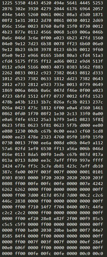
How does one edit these ROMs that are stored on chips? By a process known as dumping which uses special tools such as a ROM burner, the data from these ROMs can be copied onto the computer and stored as a ROM image file. A ROM image file is basically a file that contains binary code which can be executed on a CPU that the code was intended for. In the context of our project, it would be the Chip 8 CPU. The picture below shows an example of a ROM image file for the Chip 8 game Space Invaders. As it can be seen, it consists of binary code in hexadecimal format and the code can be seen by just simply opening it with a simple text editor that can read code written in hexadecimal format. In this example shown, the code was displayed in Sublime Text.
All of the Chip 8 and SuperChip 8 ROMs that we have obtained are freely available online and they come in the form of ROM image files.
Design Steps in creating the ROM
In the Chip 8 ROM that we have decided to create, we wanted to have the following features:
- A title screen that displays our initials and showcases us as the creators of the ROM
- The ROM must be a new or different ROM that is not available anywhere else
1. Understanding the Instruction Set
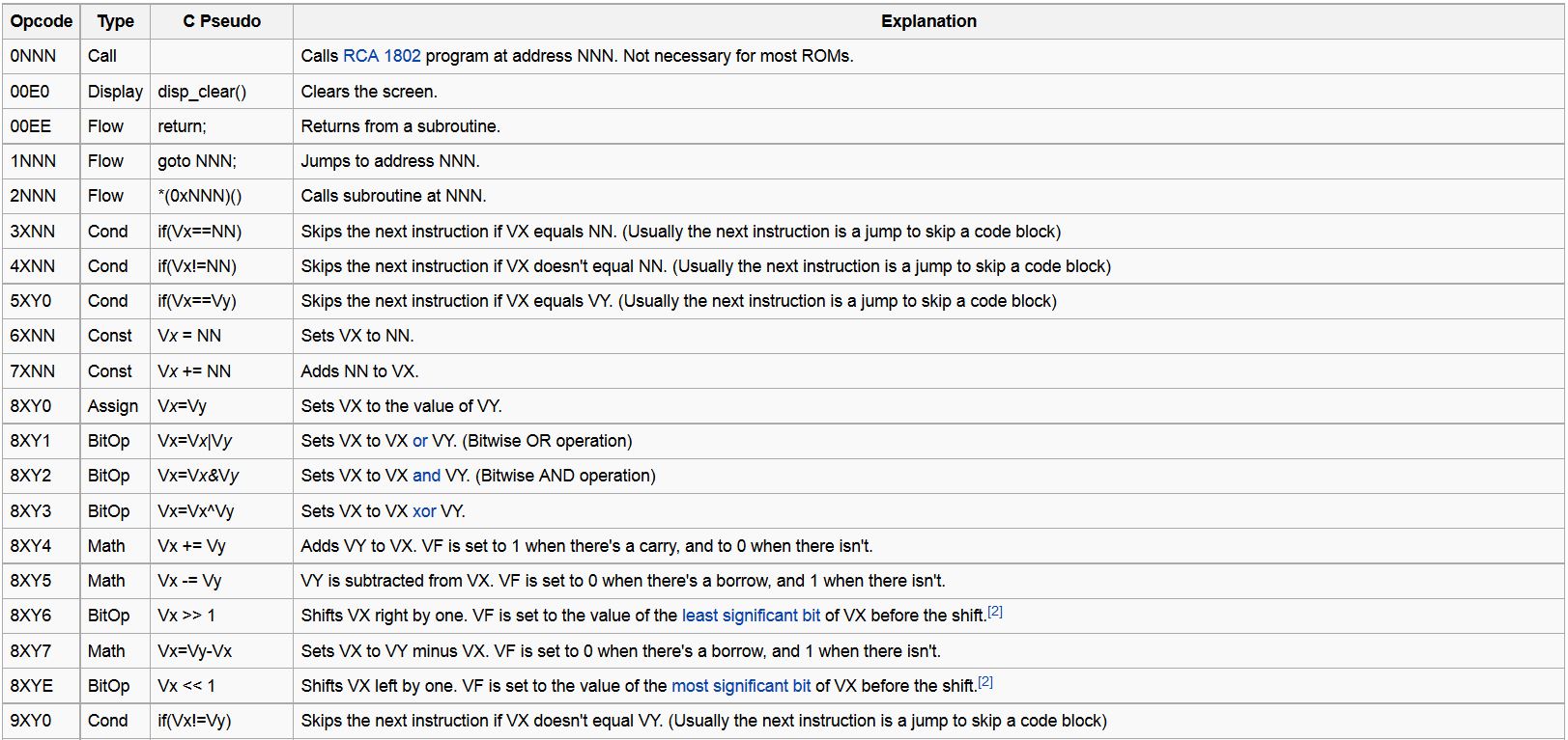
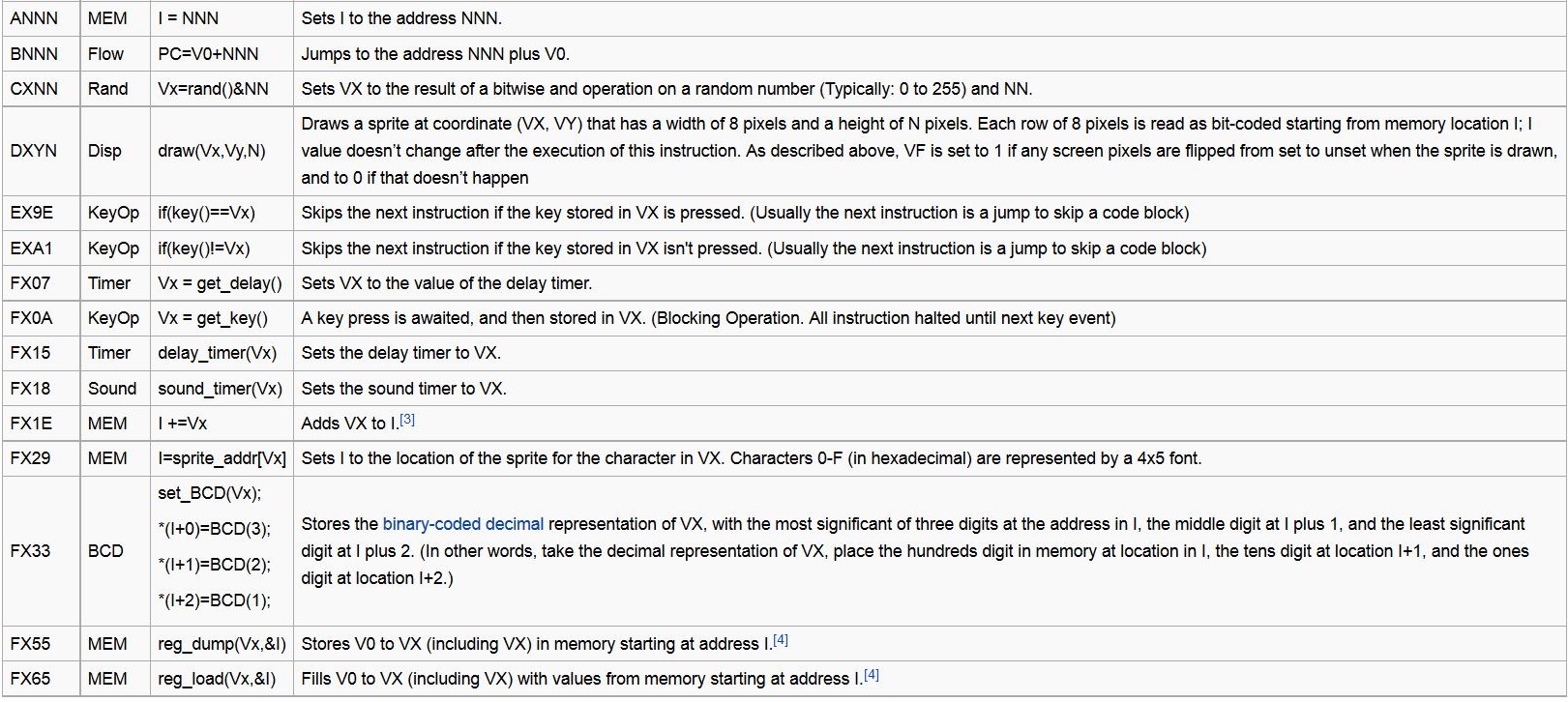
The first approach that we took in designing our custom ROM was to first read and understand the entire Chip 8 instruction set. This is important because each instruction serves a different purpose and performs a different function. Furthermore, instructions are often chained together to perform a specific function. Thus, it is extremely crucial to understand what each Chip 8 instruction does in order to determine the instructions that are needed to achieve our goal. The picture below shows the full instruction set for Chip 8. Even though there are many instructions available, not all instructions are used to write our ROM.
2. Drawing Sprites for the Title Screen
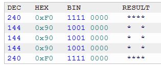
In order to draw sprites onto the screen, we used an idea similar to what was used for the standard Chip 8 font set. In the Chip 8 font set, each number or character is 4 pixels wide and 5 pixels high and they have preloaded into Chip 8's memory. For example, the following sequence of hexadecimal numbers represents a zero:
- 0xF0, 0x90, 0x90, 0x90, 0xF0
Even though this sequence of hexadecimal might look random, it actually displays a zero in the following format as shown in the picture below.
Using a similar concept, we preloaded the fonts that we needed into memory so that our ROM will be able to access the memory to obtain the fonts that we needed. We added the following additional fonts to memory:
- 0xF0, 0x90, 0xF0, 0xA0, 0x90 (Displays R)
- 0xD8, 0xA8, 0x88, 0x88, 0x88 (Displays M)
- 0x90, 0x90, 0x60, 0x60, 0x60 (Displays Y)
- 0xF0, 0x90, 0xF0, 0x80, 0x80 (Displays P)
- 0x90, 0xA0, 0xC0, 0xA0, 0x90 (Displays K)
- 0xD0, 0xD0, 0xB0, 0xB0, 0x90 (Displays N)
- 0x00, 0x00, 0xF0, 0x00, 0x00 (Displays -)
After loading these fonts into memory, the next step would be to actually draw these sprites onto the screen. After analysing and understanding how sprites are drawn in other ROMs, we used the following sequence of instructions in order to draw a sprite onto the screen. In this case, we are trying to draw the letter A:
- a032 6015 d015
The first opcode "a032" performs the following operation. It stores the sprite address located at memory address 0x032 (array index decimal 50) in the I(index) register of Chip 8. The hexadecimal code for the letter A is stored at memory address 0x032 and the I register is simply a register that stores memory addresses.You may refer to the diagram of the full instruction set above for a description of the opcode. The next opcode "6015" stores 0x15(decimal 21) at register V0. This opcode is executed so that the next opcode can use this value. The final opcode is "d015". This opcode draws a sprite at the (x,y) coordinate (21,0) that is 5 pixels high and 8 pixels wide. In other words, the letter A has been drawn.
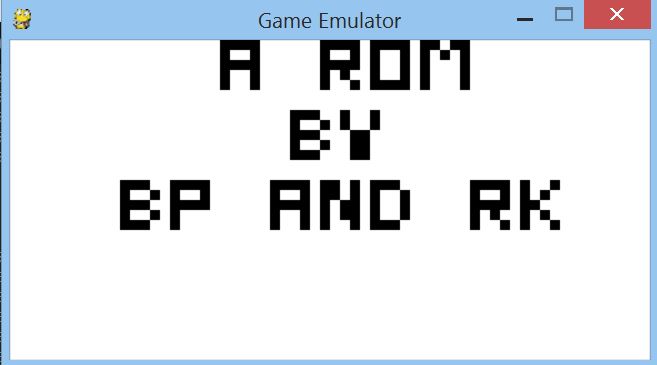
By following this general approach, we could draw out all other letters on the screen by storing the sprite address that we wanted to draw in register I and by changing the coordinates of where the sprite is supposed to be drawn. Finally, we managed to obtain our title screen which consists of our initials:
3. Transitioning to Game from title screen
The next step is to create a transition from the title screen to the game itself. The transition occurs after a timer count reaches 0, so the title screen is only displayed for a few seconds. This is achieved with the execution of the following sequence of instructions:
- 603f f015 f007 3000 1264 00e0
The first opcode "603f" performs the following operation. It stores the value 0x3f at register V0. This value will be the timer countdown value. The next opcode "f015" is executed to set the delay timer to the value stored in register V0. In each cycle that the emulator executes, this timer value will be decremented by 1. The next opcode "f007" sets register V0 to the value currently stored in the delay timer. "3000" checks whether the value in register V0 is equals to 0. If the value is equal to 0, we skip the opcode "1264" and execute the opcode "00e0", which clears the title screen. Otherwise, if the value in register V0 is not equal to 0, we loop back to the start of the instruction sequence by executing "1264", which jumps to the memory address that contains the first instruction of this sequence. With this implementation, we are able to achieve a simple implementation of a timer countdown that causes a simple transition.
4. Making the Game
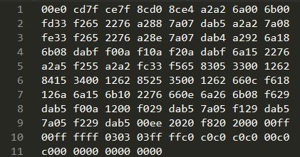
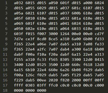
This was the most difficult step in designing our custom ROM as we did not have a disassembler or debugger to aid us. Thus, we had to edit the hexadecimal code of one of the available ROMs in order to make a new game. Eventually, we managed to make a subtraction game that was based off an addition game. The following picture shows the hexadecimal code of the original add ROM.
In order to make our subtraction game work, we had to make 4 main changes to the hexademcimal code of the addition game:
- Add our title screen hexadecimal code to the addition game code.
- Change the sprite that draws the addition sign to a subtraction sign.
- Change the logic of the game to implement subtraction instead of addition.
- Change memory jumps accordingly to take into account the offset from the additional instructions for our title screen.
After making the changes described above, we obtained the following code:
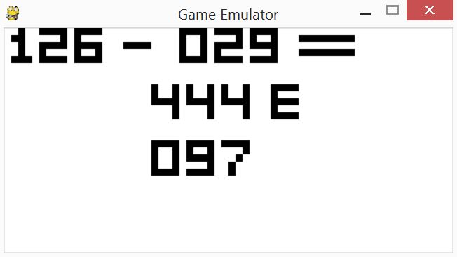
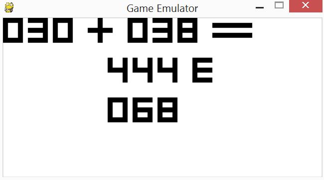
Finally, after running our ROM on the emulator that we have created, we were able to play our very own custom made ROM. The picture below is the original version of the add game.
The picture below is our own custom made ROM of subtraction.