In this project, our main goals are to emulate the Chip 8 and the SuperChip 8 emulator so that we can run Chip 8 and SuperChip 8 ROMs on our emulator.
Chip 8 Emulator
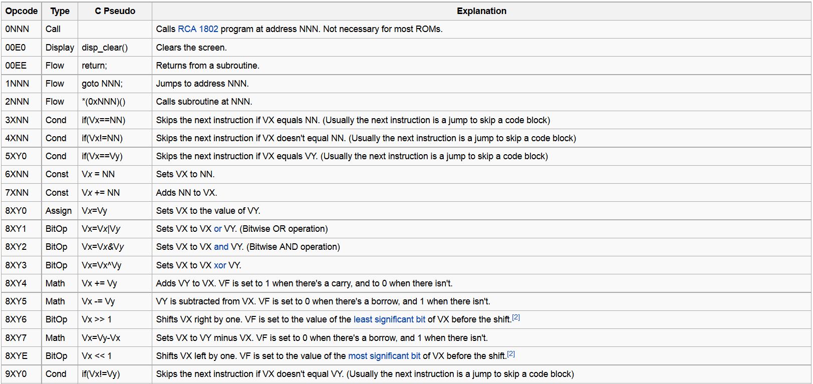
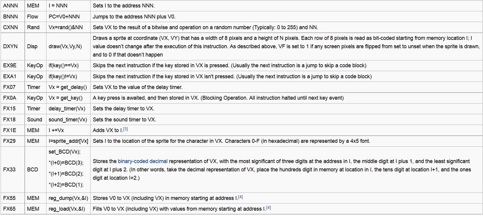
Chip 8 Instruction Set
The Chip 8 programming language is a tiny interpreted language used mainly to write simple video games. With only 35 instructions where each instruction is 2 bytes long, the Chip 8 CPU is able to support basic functionality which includes arithmetic operations, control flow, sound and simple graphics. The following table shows the complete list of instructions that we had implemented for the Chip 8 processor.
We implemented all of the opcodes in a python module. The most significant 4 bits of each opcode generally specifies the type of operation that an opcode will perform. For example, opcodes with the most significant 4 bits having a value of 8 will perform arithmetic operations. The following code excerpt is a simple example of how we implemented an assign operation for opcode 8XY0 in python for a Chip 8 opcode:
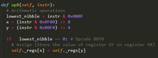
The appendix includes a link to our full source code which shows how we implemented the rest of the instructions.
Chip 8 Memory
Chip 8 has an address space of 4 KB which is byte-addressable. The addresses are stored from memory addresses 0x000 to 0xFFF. Addresses from 0x000 to 0x1FF are reserved for other purposes such as storing the standard Chip 8 fonts. Thus, all Chip 8 ROM programs always begin at address 0x200. We implemented this in python by creating an array of 4096 elements, where each element contains a byte.
Chip 8 Registers
Chip 8 has 16 8-bit registers named V0, V1, V2, V3, ..., VA, VB, VC, VD, VE, VF which is implemented with an array. The 16 registers were implemented with an array. Chip 8 also has a special I register, known as the index register which stores a pointer to a memory address.
Chip 8 Graphics
Chip 8 uses a screen size of 64 pixels by 32 pixels. The origin begins at the top left corner of the screen with positive coordinates. Graphics are displayed by drawing sprites which are 1 to 15 pixels high and 8 pixels wide. This is achieved by the opcode DXYN, where a sprite is drawn at position VX, VY with N bytes of sprite data starting at the address stored in the I register.
Chip 8 KeyPresses
Most of the Chip 8 ROMs have been written for a 16-key hex keyboard. We implemented keypresses by creating a list of 16 elements and each element corresponds to one of the first 16 hex values. Some of the Chip 8 opcodes, for example FX0A, are designed to specifically handle keypresses by waiting for a keypress in the keypress register and storing the result in one of the 16 general purpose registers V0 to VF. For more details on how these keypresses are detected, please refer to the INPUT section.
Chip 8 Timers
There are two timers, namely the delay timer and the sound timer. The timers will countdown by about 60 times per second when the values in the timers are positive. These timers are usually used to implement time-based Chip 8 games.
SuperChip 8 Emulator
After completing our Chip 8 emulator, we decided to proceed and extend our Chip 8 emulator to build a SuperChip 8 emulator that can play more advanced games. Writing the SuperChip 8 emulator was a more difficult task as there was little documentation available to help us. After lots of debugging, we are proud to present a prototype of the SuperChip 8 emulator. The SuperChip 8 emulator has the following additional features:
- A larger screen size with higher resolution
- Faster CPU Speed
- Able to run Chip 8 games too
- Larger sprite drawing is available
- Larger standard fonts are also loaded into memory
- Screen can be scrolled left, right and down
SuperChip 8 Instruction Set
In addition to the Chip 8 instructions, the SuperChip 8 instruction set has an additional 10 opcodes. They are as follows:
- 00CN: Scroll display N lines down
- 00FB: Scroll display 4 pixels right
- 00FC: Scroll display 4 pixels left
- 00FD: Exit CHIP interpreter
- 00FE: Disable extended screen mode
- 00FF: Enable extended screen mode for full-screen graphics
- DXYN: Show N-byte sprite from M(I) at coords (VX,VY), VF :=collision. If N=0 and extended mode, show 16x16 sprite.
- FX30: Point I to 10-byte font sprite for digit VX (0..9)
- FX75: Store V0..VX in RPL user flags (X <= 7)
- FX85: Read V0..VX from RPL user flags (X <= 7)
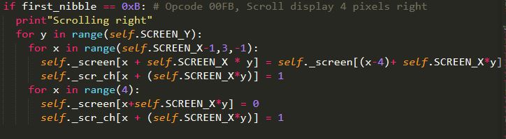
In order to implement these instructions, we extended our Chip 8 python class to create a SuperChip 8 emulator. We then implement the additional opcodes as needed. For example, the scrolling right operation allows SuperChip 8 games to implement movement, thus providing additional gaming features. The code excerpt below is an example of how we implemented the opcode that scrolls right:
SuperChip 8 Memory
SuperChip 8 also uses an address space of 4 KB which is byte-addressable. The addresses are stored from memory addresses 0x000 to 0xFFF. Addresses from 0x000 to 0x1FF are reserved for other purposes such as storing the standard Chip 8 fonts and SuperChip 8 Fonts. Thus, all SuperChip 8 ROM programs always begin at address 0x200. We implemented this in python by creating an array of 4096 elements, where each element contains a byte.
SuperChip 8 Registers
SuperChip 8 also uses 16 8-bit registers named V0, V1, V2, V3, ..., VA, VB, VC, VD, VE, VF which is implemented with an array and the special I register is also used.
SuperChip 8 Graphics
SuperChip 8 is capable of using a screen size of 128 pixels by 64 pixels, as well as the standard Chip 8 screen size of 64 pixels by 32 pixels. The screen size will be specified by opcodes that write to a screen flag that indicates whether the screen should be enlarged. The origin also begins at the top left corner of the screen with positive coordinates. Graphics are displayed by drawing sprites which are 1 to 15 pixels high and 8 pixels wide. This is achieved by the opcode DXYN, where a sprite is drawn at position VX, VY with N bytes of sprite data starting at the address stored in the I register. The opcode DXYN has also been modified such that whenever DXY0 is called with the screen flag indicating that a larger screen should be used, a 16 pixels by 16 pixels sprite will be drawn. This allows ROMs to draw more advanced and higher resolution sprites.
SuperChip 8 KeyPresses
SuperChip 8's keypresses are implemented in the exact same way as Chip 8's keypresses. For more details on how these keypresses are detected, please refer to the input section.
SuperChip 8 Timers
The SuperChip 8 emulator also has the same timers as the Chip 8 emulator. There are two timers, namely the delay timer and the sound timer. The timers will countdown by about 60 times per second when the values in the timers are positive. These timers are usually used to implement time-based SuperChip 8 games.
SuperChip 8 Flags
The SuperChip 8 emulator also has 8 additional RPL flags that are used to implement the additional SuperChip8 8 opcodes "FX75" and "FX85". These flags are implemented as an array of 8 elements.