Ping Pong Ball Balancing platform using Computer Vision and PID Control
Gabriel Fuchs (gdf42)
Taylor Stephens (tms279)
Lab 402 (section 5)
5/12/24
1 Objective
The objective of our project was to explore the possibility of balancing a ping pong ball on a flat surface whose orientation is controlled by two positional servos. We aimed to create a robust system that could support large disturbances to the ping pong ball as well as catching the ball when thrown on. This project involves a careful yet efficient combination of techniques from:
- Computer vision in tracking the ping pong ball
- PID control for updating desired servo positions
- Accompany hardware pulse width modulation to execute servo updates
- piTFT display for intuitive ease of control for a user
- Multiprocessing to ensure a necessary fast response
- A strong yet lightweight build to facilitate quick yet precise reactions
2 Project Video:
[placeholder: https://www.youtube.com/watch?v=et91Gea6CPk]
3 Introduction
In this project, we developed a Ping Pong Ball Balancing Platform that integrates advanced computer vision and precise PID control mechanisms. The primary focus was to engineer a system capable of dynamically balancing a ping pong ball on a centrally supported acrylic platform, maneuvered by two strategically placed servos. Utilizing a camera mounted directly above the platform, our system employs real-time computer vision to track the ball’s position, implemented in multiple ways both in testing and in the final implementation. This input is then processed to adjust the platform’s tilt through a finely tuned PID controller, aiming to maintain or alter the ball’s position as required. The entire operation of our Ping Pong Ball Balancing Platform is self-contained, supported by a Raspberry Pi 4B, which, along with a piTFT display, handles all system functionalities. By incorporating a battery pack to power the Raspberry Pi and a separate 6V power supply for the servos, our setup ensures complete autonomy. We’ve implemented a cron job that automatically initiates the program upon startup, eliminating the need for peripheral use or manual launch procedures. Once powered on, all interactions with the system are managed through the piTFT screen, which features a user-friendly interface designed for simplicity and ease of use. This standalone configuration allows the system to operate independently, making it versatile and user-friendly. This project not only demonstrates the practical application of embedded systems combining hardware and software but also serves as a testbed for exploring control systems and real-time image processing techniques.
4 Design and Testing
4.1 Mechancial Design
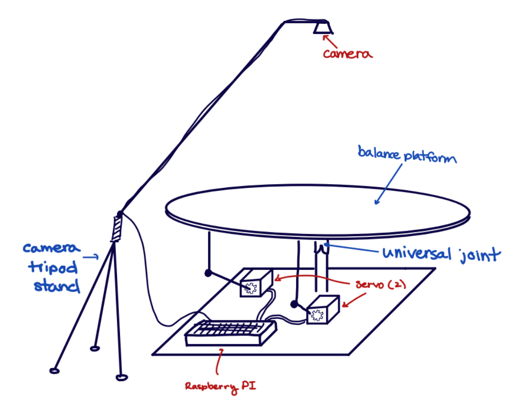
Figure 4.1.1: Design Sketch
The mechanical design of this project demanded considerable time due to the required precision and robustness of the system. Additionally, the numerous possible configurations necessitated extensive analysis to ensure the final product could achieve our goals. Initially, we considered a three-arm approach that would eliminate the need for a central joint and increase the up-and-down control of the platform. However, as we planned to use the Raspberry Pi for our main PWM signal generation, we were limited to two servos. This limitation arises because the Pi only has two hardware PWM outputs, which are essential for speed and accuracy. As a result, we were limited to a system that uses two servos, which necessitated a specific configuration: positioning the servos at a 90-degree angle to each other. This setup allows one motor to handle all adjustments along the x-axis while the other manages the y-axis adjustments. Moreover, since a plane is defined by three contact points and our design incorporates two control points, we utilized a central axis to fully define the plane and support the majority of the weight. Consequently, this central axis was strategically placed near the center of mass of the balance pad.
One of the major design challenges posed by this configuration was connecting the arms and central joint to the pad in a way that allowed for optimal orientation adjustments. The simpler solution involved using a universal joint attached to a central rod. When oriented correctly, this setup permitted rotation in the x and y directions independently. We decided to position the universal joint near the top of the beam, following an analysis of the pad’s range of motion in both configurations. Placing the joint lower resulted in greater lateral movement of the pad, which initially might seem beneficial. However, this lateral movement occurred at angles not conducive to central balancing and was therefore eliminated as an option. Generally, positioning the joint higher up provided more stability, which seemed preferable for the first prototype.
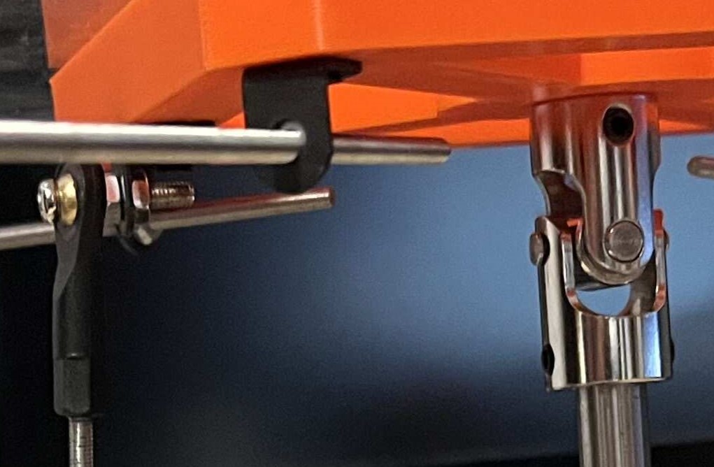
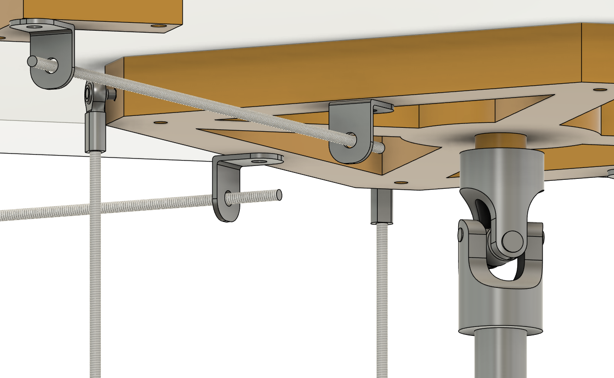
Figure 4.1.2: Universal Joint
The more challenging issue in allowing for free pad reorientation involved securing the connecting rods that were attached to the servos. We identified that a universal joint, while functional, might be too restrictive under some circumstances and difficult to source in the small size we required.As such, we opted to use ball end joints at each end of the connecting rod. These joints provide greater flexibility and a wider range of motion, which was crucial for the precise control needed in our design.
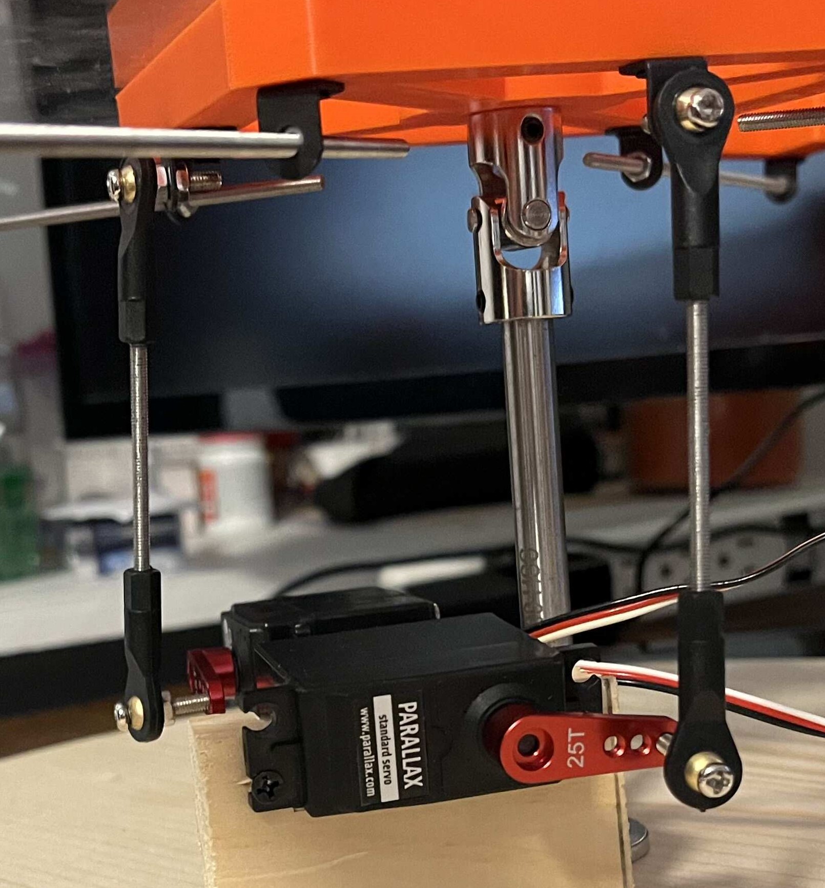
Figure 4.1.3: Ball End Caps
Another design challenge we faced was figuring out how to connect the various components to the balance pad without compromising its integrity. Initially, drilling holes through the pad and securing the various connecting rods with nuts and bolts seemed like a straightforward solution. However, this would compromise the flat, undisturbed surface of the pad, which we aimed to preserve.
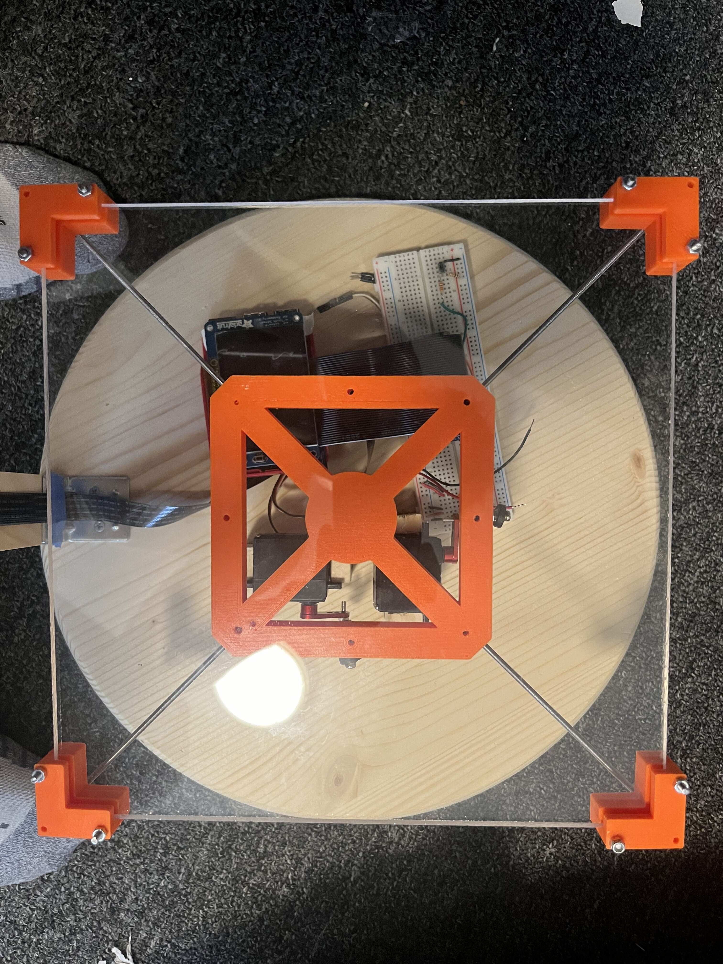
To address this, we devised a solution involving a central hub that holds the acrylic sheet in place using four clips at each corner of the plastic sheet. These clips were connected to the central hub using 3M threaded rods and mini L-brackets that linked the hub and the clips. Given the need for customization of the hub and corner clips, we opted for 3D printing these components, allowing for precise adjustments and fitment tailored to our specific requirements.
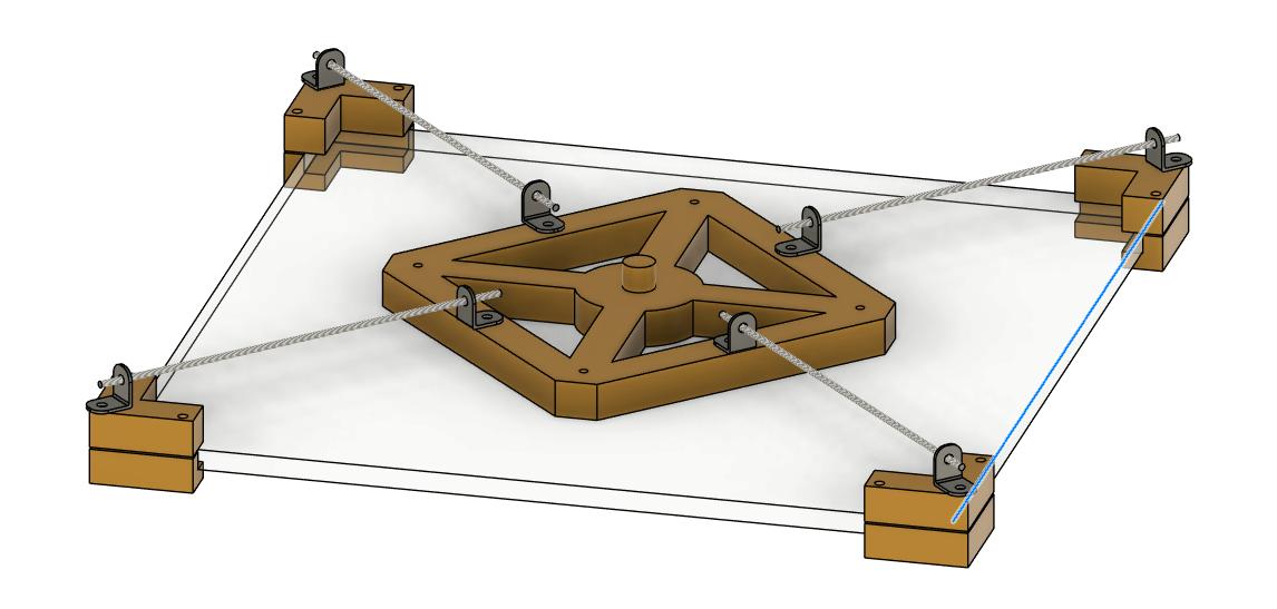
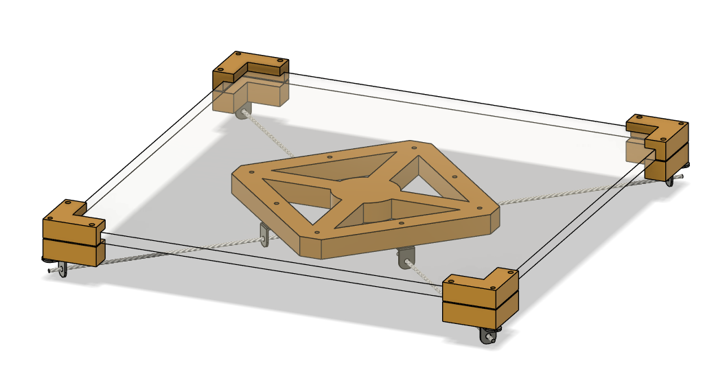
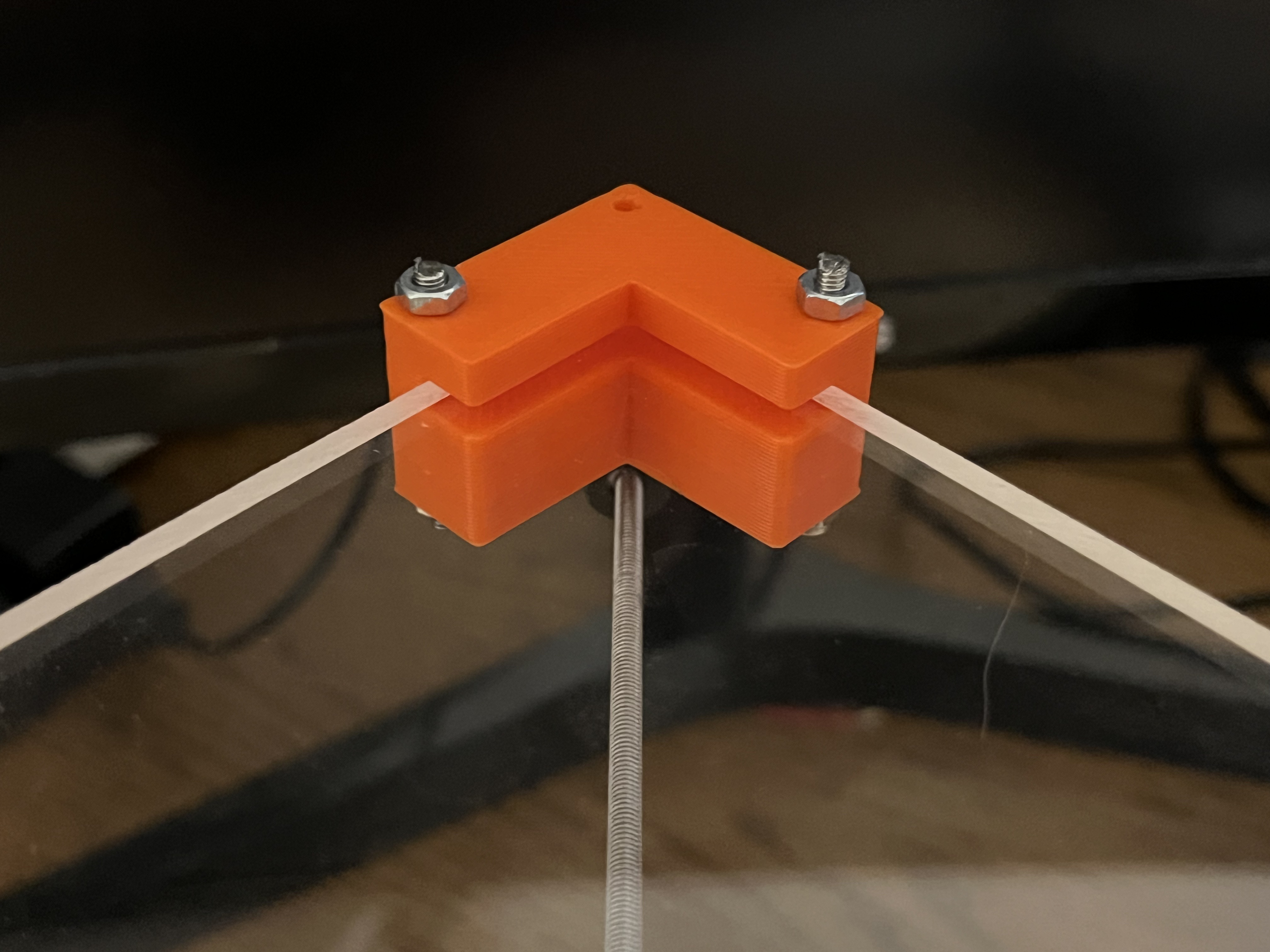
Figure 4.1.4: Balancing Pad Clips
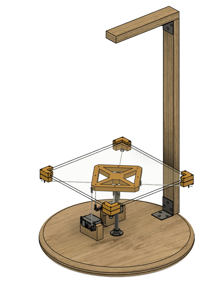
The supporting structure of the system is far simpler than the design considerations previously described. We utilized the head of a stool for the circular base of the system and a wooden beam measuring 0.75 by 1.5 inches to centrally mount the PiCamera above the platform. Excess portions of this beam were shaped to accommodate the servos and were glued to the base platform. This straightforward approach provides a stable and functional base for the more complex components of our system.
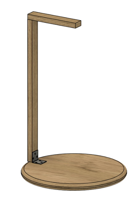
Figure 4.1.5: Camera Stand Design
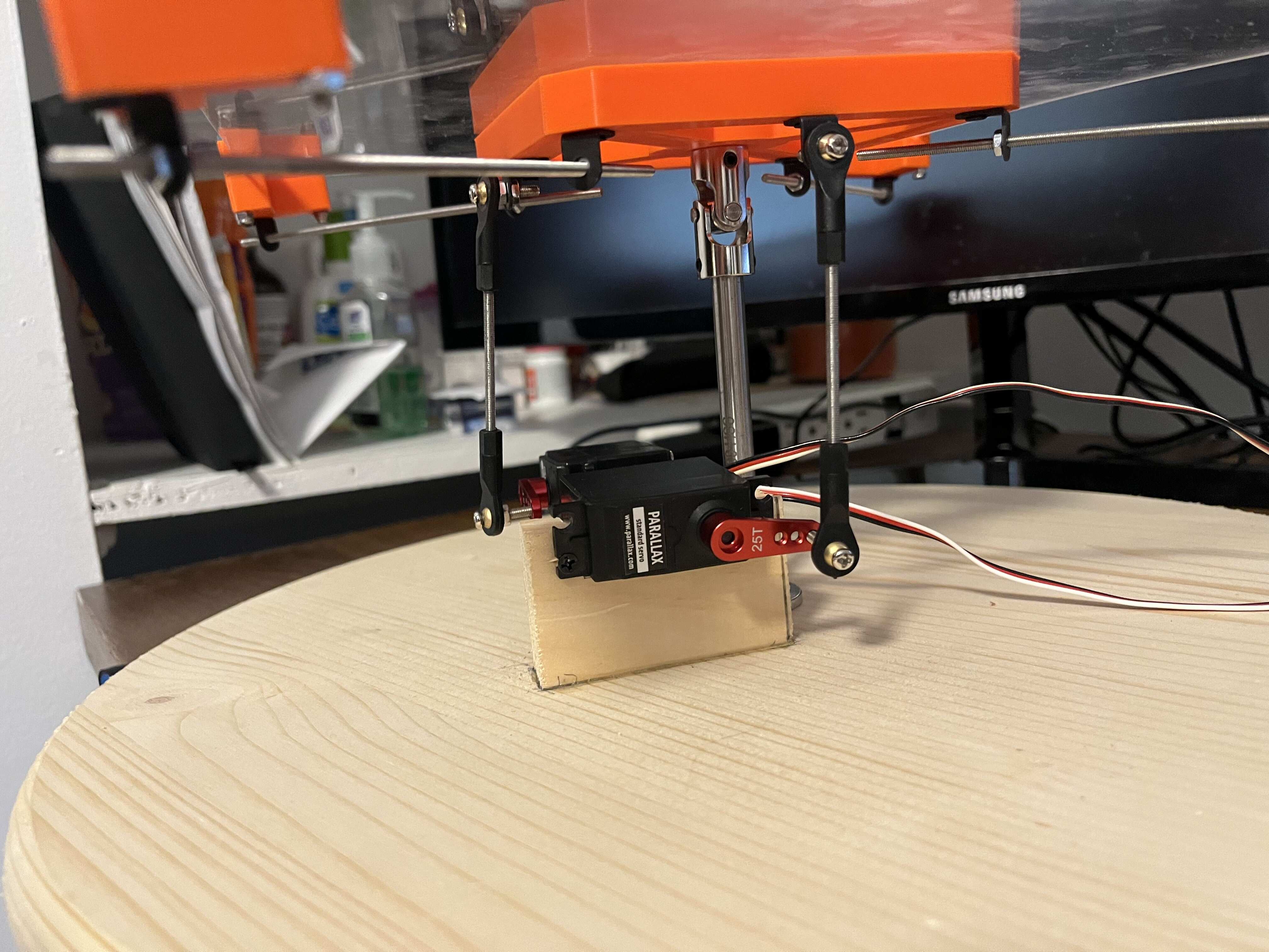
Smaller design decisions included the use of a 3cm servo horn, which was positioned horizontally in its default state and attached 3 inches away from the central rod. This placement balanced the need for fast yet precise control without bearing too much of the load from the acrylic sheet and hub systems. This strategic positioning ensures effective leverage and movement control while minimizing the stress on the central structure.
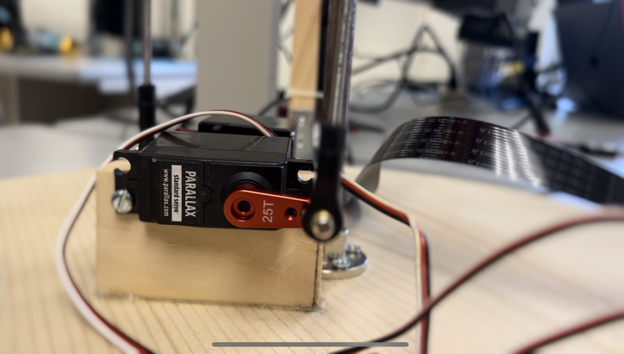
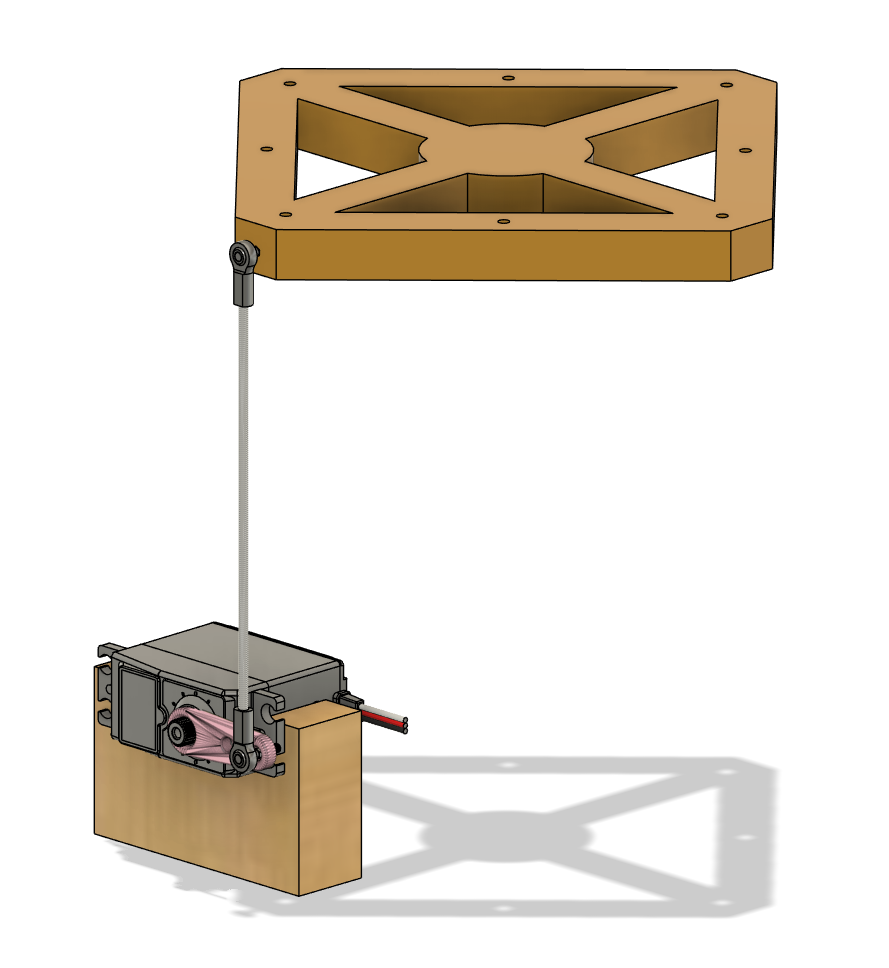
Figure 4.1.6: Strategic Positioning of Motor Arm
Final views are depicted below:
.jpg)
Figure 4.1.7: Completed Hardware
4.2 Adding the Electronics
The structural components of our design were securely fastened using a combination of nuts and bolts, wood glue, brackets, and 3D printed clips under tension. This array of fastening methods ensured a robust and durable assembly
The electrical connections in our project were relatively straightforward. We started by using standard positional parallax servos available in our lab. These servos operate under 6 volts connected to the red pin, with the ground connected to the black pin, and the data pin connected directly to the PWM outputs on the Raspberry Pi (GPIO pins 12 and 13 for each servo, respectively). This setup provided a simple and efficient way to control the servos directly from the Raspberry Pi without needing complex wiring or additional control hardware.
The piTFT, serving as a mini display and touchscreen, was mounted directly onto the Raspberry Pi. To accommodate this setup while still allowing access to the pins for motor control, we used a halfway cable, a method consistent with practices from labs conducted throughout the semester. This configuration ensured that the piTFT was both functionally integrated and conveniently accessible for real-time control and monitoring tasks.
Lastly, we needed to attach the camera. Initially, we attached the camera using tape to the top of the stand. This was good for testing, but for the final version we used zip ties in order to make the camera much more secure. We then needed to locate the camera module port on our Raspberry Pi. After lightly pulling up the plastic clip, we inserted the camera module’s ribbon cable into the port. After pushing the plastic clip back down, the camera was installed.
4.3 Initial Testing
Once the system was all assembled we wanted to do some initial testing of the servos, the Pi Camera, and PpenCV in order to ensure that everything was working properly.
4.3.1 Testing The Servos
Over the course of the project, we encountered some skepticism regarding the servo motors we were using. Initially, we opted for standard Parallax servo motors, as our lab had used ones available. These servos are controlled by a 50Hz PWM signal, whose duty cycle can be altered to determine the rotation angle of the servo. The control code for original tetsing of the servos is shown below:
import pigpio
import RPi.GPIO as GPIO

# Set GPIO numbering mode to Broadcom SOC Channel number
GPIO.setmode(GPIO.BCM)

# Initialize pigpio to connect to the pigpio daemon, necessary for hardware PWM
pi_hw = pigpio.pi()

# Mapping of motor names to GPIO pins
motors = {'1': 12, '2': 13}

# Control loop flag
running = True
# PWM frequency in Hz (50 Hz is typical for servos)
freq = 50

while running:
    m_in = input("motor: ")  # Motor number input
    s_in = input("rotation: ")  # Desired rotation angle

    if s_in == "quit":
        running = False  # Exit loop
    elif int(s_in) > 180 or int(s_in) < 0:
        # If input angle is out of valid servo range, ignore it
        pass
    else:
        # Calculate PWM duty cycle for the given angle
        theta = int(s_in)
        t_high = theta * 10 + 620  # Calculate pulse width in microseconds
        duty_input = int(((t_high / 10**6) / (1 / freq)) * 1000000)
        # Set the hardware PWM parameters (pin, frequency, duty cycle)
        pi_hw.hardware_PWM(motors[m_in], freq, duty_input)

# Reset the PWM values to zero to stop the motors
pi_hw.hardware_PWM(12, 0, 0)  # Motor 1
pi_hw.hardware_PWM(13, 0, 0)  # Motor 2
pi_hw.stop()  # Close pigpio resources
One notable aspect of our project is the use of hardware PWM, which takes a duty cycle input scaled to 1 million in an effort to reduce computational imprecision. For example, a duty cycle of 0.75 would be represented as 750,000 in our system. It’s important to highlight that if one were to replicate this project, they should be aware that each brand or type of positional servo might use a different range of duty cycles to achieve desired positions. Therefore, converting from the desired angle to the appropriate duty cycle can vary between different servos. In our final implementation, this calculation was encapsulated within a helper function to simplify the code and enhance usability.
During our testing phase, we frequently observed these servos oscillating as they tried to reach an assigned position, or sometimes they were simply be unable to move likely due to torque limitations. In retrospect, we concluded that this was likely caused by a combination of servo fatigue and wiring connection issues. Once we got the system roughly working, we feared that the limitations of these servos would severely restrict our success; consequently, we decided to invest in new high-torque servos with faster rotation speeds.
However, the transition was not as smooth as expected. Although the new servos supplied more torque, had no overshoot, responded more smoothly, and seemed faster, our success in balancing the ball paradoxically declined. Even after significant PID tuning, the new servos inexplicably underperformed compared to the original ones. We hypothesized that this might be due to how these servos internally processed the duty cycle updates, but ultimately, we returned to the original Parallax servos for our final setup.
In hindsight, and after further testing, it seems that the Parallax servos could be extremely smooth with steady updates. This observation led us to hypothesize that perhaps they simply required more fine-tuned PID settings and that their initial shakiness was a result of shaky inputs, which are expected given the precise balancing task at hand.
4.3.2 Testing the Pi Camera
Next, we tested the camera. In order to do this, we first had to enable the camera in the Raspberry Pi Configuration tool. Under the interfaces tab, we had to check the ‘Enabled’ button for the camera. After a reboot of the Raspberry Pi, the camera was connected. We then needed to install the picamera2 Python package in order to test it. This was done by running the following commands:
sudo apt install -y libcamera0 libcamera-dev
pip install picamera2
After picamera2 was installed, we wrote a simple test script to get an image and save it to the /home/pi directory.
from picamera2 import Picamera2
import time

def capture_image():
    # Initialize the Picamera2 object
    picam2 = Picamera2()

    # Configure the camera with default settings
    picam2.start_preview()

    # Sleep briefly to allow the camera to adjust to lighting conditions
    time.sleep(2)

    # Capture an image
    picam2.capture_file('/home/pi/image.jpg')  # Modify '/home/pi/image.jpg'

    # Stop the camera
    picam2.stop_preview()

if __name__ == "__main__":
    capture_image()
After confirming that the image was properly saved to the right location, we opened the image and confirmed that the camera was working.
4.3.3 Testing OpenCV
Finally, we needed to install and test if OpenCV working properly.
We installed OpenCV using the following command:
sudo apt-get install python3-opencv
After OpenCV was installed, we created a small test script to see if it could process images from the Raspberry Pi Camera.
from picamera2 import Picamera2
import cv2
import numpy as np

def capture_and_process_image():
    # Initialize the Picamera2 object
    picam2 = Picamera2()
    picam2.start_preview()

    # Configure the camera with default settings and a suitable preview size
    config = picam2.create_preview_configuration()
    picam2.configure(config)

    # Start the camera
    picam2.start()

    # Capture an image to a NumPy array
    frame = picam2.capture_array()

    # Stop the camera preview and release resources
    picam2.stop_preview()
    picam2.close()

    # Convert the captured image to grayscale using OpenCV
    gray_frame = cv2.cvtColor(frame, cv2.COLOR_BGR2GRAY)

    # Display the grayscale image
    cv2.imshow('Grayscale Image', gray_frame)
    cv2.waitKey(0)  # Wait indefinitely until a key is pressed
    cv2.destroyAllWindows()

if __name__ == "__main__":
    capture_and_process_image()
Running the script displayed an image in grayscale in an OpenCV window which confirmed that OpenCV was installed correctly and could process images.
4.4 Tracking
There are two common approaches to tracking a ball object. The first approach we tried was to do color detection based on the color of the ping pong ball and return the position of the ball based on the results. This was achieved by taking an image with the Pi Camera, converting the image into the HSV color space (Hue, Saturation, Value) and then applying a mask to isolate color reigions. The code for this is shown in Appendix A. After running the code we got the following output:
![]()
Figure 4.4.1: Initial Ball Tracking Output
This was good as we could isolate the ping pong ball from the background, but when we tested it on the fully constructed system we found that the organge color of the ping pong ball conflcited with the orange color of our balancing pad. To fix this, we decided to try using a white ping pong ball. The white ping pong ball tracked better, but we found that differences in the lighting conditions of the room would drastically change the shade of white which was throwing off our detection. To solve this issue, we widened the HSV bounds for the white ping pong ball and applied a circularity filter to only detect circular objects.
This solution would have worked well enough for a slower-paced system, but the fast moving nature of our system required a different solution. After trying the color-detection method, we then decided to switch to object tracking. OpenCV comes preinstalled with a number of different object tracking algorithms for us to use. These are documented here. We decided to use the CSRT tracking algorithm which provides a good balance between accuracy and speed. Implementing the CSRT algorithm on top of our existing code required almost an entire rewrite as tracking algorithms in OpenCV have a different implmentation.
First, you need to pass a static frame to the tracker and define a region of interest. This code snippet accomplishes this:
# Capture a frame from the camera
    frame = picam2.capture_array()  # Capture a frame as a NumPy array
    frame = cv2.cvtColor(frame, cv2.COLOR_BGR2RGB)

    frame = cv2.resize(frame, (320, 240))  # Resize to 320x240

    frame = cv2.flip(frame, 1)

    global tracker
    global tracker_init

    if tracker_init == False:
    # Use the first frame to set up the initial tracking region
        bbox = cv2.selectROI("Frame", frame, fromCenter=False, showCrosshair=True)
        tracker.init(frame, bbox)
        tracker_init = True
        x, y, w, h = [int(v) for v in bbox]
        center = (x + w // 2, y + h // 2)
        cv2.destroyAllWindows()
The cv2 “selectROI” function opens a new OpenCV window with the frame and requires the user to click and drag to define a region of interest for the tracker. After a region of interest is selected and a frame is provided to the tracker, the tracker can then update itself based on new frames. The update block looks like this:
# Update tracker and get the new position of the object
    success, bbox = tracker.update(frame)
    if success:
        x, y, w, h = [int(v) for v in bbox]
        center = (x + w // 2, y + h // 2)
        #print("Tracking object at:", center)
        # Draw bounding box
        cv2.rectangle(frame, (x, y), (x + w, y + h), (255, 0, 0), 2, 1)
    else:
        print("Tracking failure detected")
The center variable can then be passed to other places in the code for accurate ball tracking. One small problem with this code is the need to select the ROI for each initialization. This works fine for testing, but one of our larger goals was the ability for the system to be able to catch the ping pong ball and start balancing it. Obviously, there would be no time for the user to manually select the ball on the plate. This led to the creation of two operating modes for our system. In manual mode, the user places a ball on the plate and selects the ball on the piTFT screen. This is similar to the tracking implementation detailed above. In automatic mode, the ball can be thrown onto the plate and autodetected and tracking starts working.
To get automatic mode working, our tracking implementation needed to be slightly modified. Instead of manually selecting a region of interest, a frame is first captured from the Pi Camera and run through different filters to remove the background and apply morphological operations. Then, we use the Hough Circles algorithm to detect circles. After this, we check for 3 consistent frames to remove any circles that are detected due to light or camera noise. After a circle has been confirmed (indicating that the ball has been found), we pass the frame as well as the region of interest around the ball to the tracker to begin initilization. This approach worked quite well, as luckily the OpenCV filtering and Hough Circle algorithm can run fast enough that the ball does not roll off of the plate before it is detected.
After writing the automatic tracking code, the ball detection and tracking worked quite well for a variety of different colored ping pong balls. Our automatic tracking code is available in Appendix B.
4.5 PID
Despite existing PID libraries existing for Python, we decided to implement our own PID controller as it is pretty simple to get working. PID stands for Proportional-Integral-Derivative and is a type of feedback control system used to maintain desired output levels. For our system, that desired setpoint is the coordinates of the ball being in the center of the balancing pad.
To create our PID controller, we created a new class called PID. This class has a number of different initialization parameters including constants for P, I, and D, the desired setpoint, and a min and max angle. The PID class has two functions called “update” and “scale_to_angle”.
The “update” function calculates the desired PID control output for given feedback. It takes in the current position as an argument and calculates the error by subtracting the current position from the setpoint. It then adds this error to the integral value. It calculates derivative by subtracting the last error reported from the current error. Then it does the output calculation with the following function:
# PID output calculation
output = (self.kp * error) + (self.ki * self.integral) + (self.kd * derivative)
In this function, kp, ki, and kd correspond to the PID coefficients. After it calculates the output, it passes the output to the “scale_to_angle” function. The “scale_to_angle” function takes in the PID output and adds it to 90 degrees (the neutral angle for the servos). It then clips the output to be within the maximum and minimum allowable angles. The final angle is returned to the update function.
Lastly, the update function sets the “last_error” variable to the current error and returns the angle. Our full PID controller code is available in Appendix C. We instantiate one PID controller for each motor.
The output of our two PID controllers is sent to a function called “update_motors”. This function takes in two angles and calculates the proper duty cycle to set the motors. This function is available in Appendix D.
4.6 PiTFT and MultiProcessing
Once the balance pad was operational, we aimed to transform it into an embedded system that allowed user interaction through touch control on the piTFT. This addition significantly increased the computational load per frame from the piCamera, necessitating a shift to multiprocessing: we split the tasks into one process handling the piCamera frame acquisition, PID control, and motor updates, and another process managing all piTFT touch inputs and display updates.
Initially, we considered threading, which would have been simpler to integrate; however, due to Python’s Global Interpreter Lock (GIL), threading wouldn’t allow parallel execution as it restricts execution to one process at a time. While threading can be useful for I/O-based tasks, it was unsuitable for our needs because the balance pad’s operations are continuous, and piTFT interactions, though less frequent, still require consistent processing power. Consequently, we opted for multiprocessing, ideally allowing processes to run in parallel on different cores.
Multiprocessing complicates the sharing of information between processes. To address this, we employed multiple queues to manage data flow while minimizing race conditions:
- Control Queue: The piTFT writes updates based on user inputs, and the balance pad reads these updates to modify the system’s physical state.
- Image Queue: The balance pad writes captured frames from the piCamera to this queue, which the piTFT reads to display frames in manual selection mode.
- Location Queue: When a location on the piTFT is pressed, the corresponding data is sent to this queue for the balance pad to use for tracking purposes.
- K-Value Queue: This is used for “party mode,” where the piTFT sends updates for changes in K values depending on user interaction speed, and the balance pad system adjusts accordingly.
Regarding the UI design for the piTFT, we found that creating the entire display—including titles and buttons—in Photoshop was advantageous. This allowed for quick positioning within a 320x240 pixel environment and immediate loading onto the piTFT as a single image. This approach not only facilitated a more appealing design but also simplified the update process to the screen buffer, requiring only a single update before a screen flip rather than multiple updates for each component.
Additionally, this facilitated a simpler button detection scheme. In the main class for our Raspberry Pi’s UI handling, we could easily detect button presses by matching touch coordinates to the predefined button locations on the loaded image, as defined by a pygame rect object. This integrated approach helped maintain the system’s responsiveness and user-friendliness despite the increased computational requirements.
4.7 Cron
The last piece of the puzzle was getting our code to run on bootup. This was done using Cron and by modifying the crontab.
We first created a shell script that waits for 10 seconds, starts the pigpiod deamon, and then starts our Python code. We wait for 10 seconds in order to ensure the necessary starup sequence gets executed before our code starts to run. We thought that this was all that was necessary for our code to run. Unfortunately, on bootup, we either got a blank white screen or a program that couldn’t control the motors. We determined that the issue had to do with the pigpiod deamon. For some reason, when starting the deamon on boot with the crontab the deamon does not start properly. After reading online we decided to add the pigpiod to system services by running the following command:
sudo systemctl enable pigpiod
Weirdly enough, we were still running into the same errors after running this on the operating system and removing the pigpiod from the crontab. After hours of headscratching (yes literally hours), we unplugged the keyboard, mouse, and networking from the Raspberry Pi. Unplugging these things seemed to fix our issue. The Raspberry Pi boots up and our program runs successfully and is able to control the servos. We have no guess as to why this fixed our issue.
4.8 Party Mode
As a fun addition to our project we decided to create an easter egg called party mode. When the user clicks the bottom right corner of the screen, the balancing pad spins in a circle at a variable speed which the user can control on the touch screen.
The party mode implementation works by using a sine wave to control the desired angle. The desired angle is then converted to a duty cycle and the motors are updated. The rotation can get faster or slower by increasing/decreasing the frequency of the wine wave. A picture of the party mode GUI interface can be seen below.
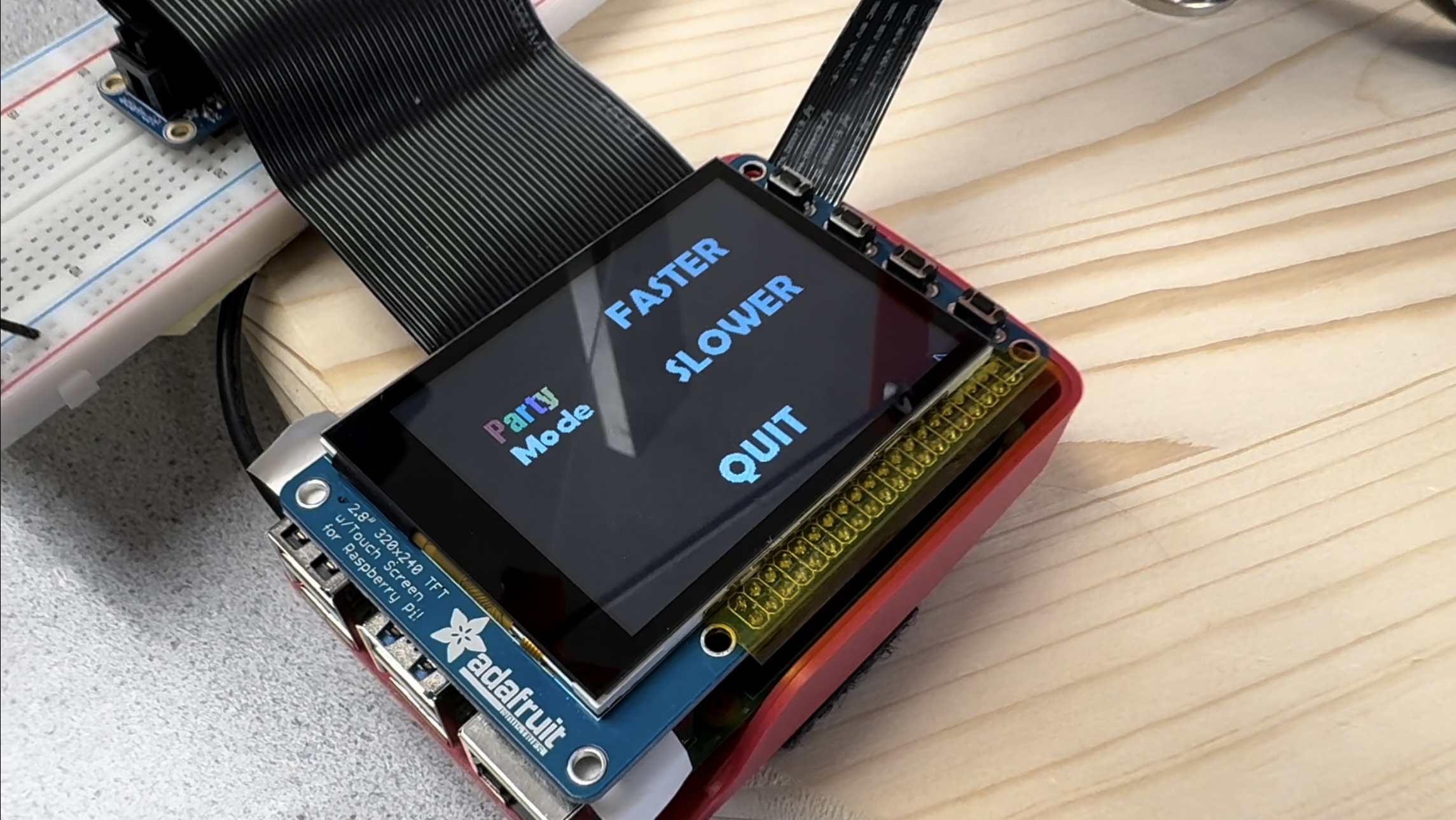
Figure 4.8.1: Party Mode GUI Interface
5 Results
In our initial project proposal we set out to complete the following goals:
- Simple balance of a ping pong ball to equilibrium in the center
- Pattern movement of ping pong ball through PID with an updating target location
- Catching the ping pong ball
- Balance of a steel ball
With these goals in mind, we accomplished 3 out of our 4 original goals. Our system was able to successfully balance a ping pong ball to equilibium in the center. In manual mode, our system is able to balance the ball to a different location other than the center on the balancing plate through PID. The target location of the ball can be updated by placing the ball in a different starting origin. The only goal we did not accomplish was the balance of a steel ball. We included this goal because steel is less frictitious than a standard ping pong ball and the weight of steel would cause it to roll faster. Unfortunately, due to time constraints, we were not able to test whether our system could properly balance a steel ball.
Almost everything went as planned with our project. We kept on pace with our original outlined schedule very well. The only component of the project that was not as smooth had to deal with the servos. The original servos we had were buggy and very jittery. At one point, we thought they had stopped working completely. Weirdly enough, they eventually just started working again. They were still jittery, but they were able to respond to PWM inputs quickly and with sufficient torque which was all that was necessary for our system. We tried swapping these motors out with new ones that we bought online but the ones we got online did not respond to our input fast enough, meaning that they would not be a good fit for our system.
6 Conclusions
Our project was able to balance a ping pong ball with manual and automatic tracking, catch a ping pong ball, and balance a ping pong ball to a specific position. We also included a fun easter egg called party mode, where the system spins the balancing plate in a circle at a variable speed (controlled by the user). Overall, we’d say our project was a major success given that we completed the main goals of our system.
By completing this project, we learned a lot about Computer Vision with OpenCV, PID control, and about taking an idea from the design phase to a complete system. One specific insight we learned was about ball tracking. For fast-moving systems, it is better to use an object tracking algorithm rather than rely on color detection. We also learned more about how OpenCV handles and processes images when doing object detection and object tracking. With PID control, we learned how to manually determine PID coefficients to stablize a system. This took hours of experimentation, but with specific testing methodology we were able to find suitable coefficients.
There was only one method that did not really work for our system. As mentioned earlier in this report, we discovered that object detection would not be a fast enough method to track the ping pong ball for our needs. We instead decided to opt for object tracking which ended up being much faster.
Future Considerations
Given more time and resources there are a few improvements we would like to make to this project.
For one, we would like to take the time to examine and select better servos. The servos we used for our project were fine, but higher torque servos that reacted faster to PWM updates would make our system much smoother and more performant. With higher quality servos, the balancing pad would be able to catch a thrown ping pong ball in most scenarios rather than just some.
Secondly, we would like to add more degrees of freedom. With more degrees of freedom and more servos, we could achieve a much more stable system. The ball could balance in the center much easier and faster. It would also require less work for each individual motor, giving the system a longer lifespan.
Lastly, it would have been nice to test a steel ball on our system to see if the system could balance a faster moving ball. This would’ve given us a better idea about how our system performed in stress-test conditions.
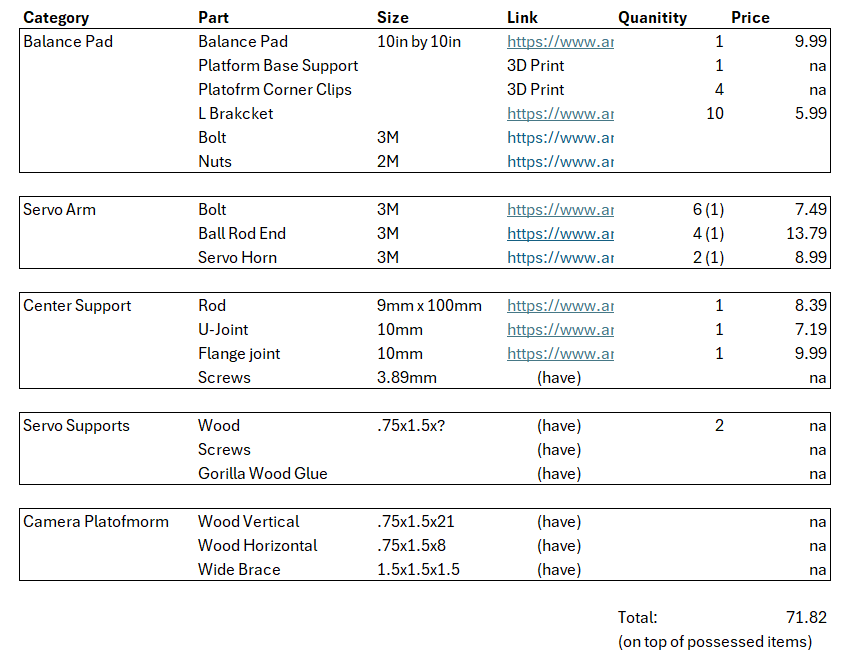
Parts Link
Team Member Contributions
Both Taylor and Gabe split work evenly on this project. Gabe took charge of constructing the device as well as helping with the code. Taylor wrote the majority of the code with help from Gabe. Both the final video and website were worked on by both Taylor and Gabe.
References
Appendix
Appendix A
Initial Color Mask Ping Pong Ball Tracking Code:
import cv2
import numpy as np
from picamera2 import Picamera2

# Initialize the Picamera2 object
picam2 = Picamera2()

# Configure the camera to output color images at a reasonable resolution
video_config = picam2.create_video_configuration(main={"size": (640, 480)})
picam2.configure(video_config)

# Start the camera
picam2.start()

# Define the color range for detection (example: orange)
lower_orange = np.array([5, 150, 150])
upper_orange = np.array([15, 255, 255])

# Real-time loop to process frames from the camera
while True:
    # Capture a frame from the camera
    frame = picam2.capture_array()  # Capture a frame as a NumPy array

    # Convert the frame to HSV
    hsv = cv2.cvtColor(frame, cv2.COLOR_BGR2HSV)

    # Create a mask for the specified color range
    mask_orange = cv2.inRange(hsv, lower_orange, upper_orange)

    # Apply the mask to the original frame
    result = cv2.bitwise_and(frame, frame, mask=mask_orange)

    # Display the original frame and the detected color regions
    cv2.imshow("Original", frame)
    cv2.imshow("Detected Color", result)

    # Exit if 'q' is pressed
    if cv2.waitKey(1) & 0xFF == ord('q'):
        break

# Stop the camera and close OpenCV windows
picam2.stop()
cv2.destroyAllWindows()
Appendix B
Automatic Tracking Code:
def init_tracker(self):

  backSub = cv2.createBackgroundSubtractorMOG2()
  consistent_frames = 0

  while not self.tracker_initialized and self.on:

      self.handle_any_new_data()

      frame = self.picam2.capture_array()
      frame = cv2.cvtColor(frame, cv2.COLOR_BGR2RGB)
      frame = cv2.resize(frame, (320, 240))  # Resize to 320x240
      frame_rgb = cv2.flip(frame, 1)

      # Apply background subtraction and morphological operations
      fgMask = backSub.apply(frame_rgb)
      kernel = cv2.getStructuringElement(cv2.MORPH_ELLIPSE, (2, 2))
      fgMask = cv2.morphologyEx(fgMask, cv2.MORPH_OPEN, kernel, iterations=2)
      _, fgMask = cv2.threshold(fgMask, 128, 255, cv2.THRESH_BINARY)

      # Hough Circles to detect circles
      circles = cv2.HoughCircles(fgMask, cv2.HOUGH_GRADIENT, dp=1.2, minDist=50,
                              param1=100, param2=20, minRadius=3, maxRadius=50)

      if circles is not None:
          circles = np.uint16(np.around(circles))
          for i in circles[0, :]:
              center = (i[0], i[1])
              radius = i[2]
              if self.last_center is None or is_in_same_region(self.last_center, center):
                  consistent_frames += 1
                  if consistent_frames >= 5:
                      # Initialize tracker
                      x, y, r = center[0], center[1], radius
                      if x - r < 0 or y - r < 0 or x + r > 320 or y + r > 240:
                          # If the proposed ROI is out of bounds, reset consistent_frames
                          consistent_frames = 0
                          print("Proposed ROI is out of frame bounds, reset consistent detection count")
                      else:
                          # Initialize tracker
                          try:
                              self.tracker.init(frame_rgb, (x-r, y-r, 2*r, 2*r))
                              self.tracker_initialized = True
                              print("Tracker Initialized")
                          except:
                              consistent_frames = 0


              else:
                  consistent_frames = 0

              self.last_center = center
              if self.vision:
                  cv2.circle(frame_rgb, center, radius, (0, 255, 0), 2)
                  cv2.circle(frame_rgb, center, 2, (0, 0, 255), 3)

      if self.vision:
          cv2.imshow('Frame', frame_rgb)

          if cv2.waitKey(1) & 0xFF == ord('q'):
              break


  self.on = True
  print("leaving_initialization")
Appendix C
PID Controller Class:
class PID:
    def __init__(self, kp, ki, kd, min_angle, max_angle, setpoint):
        self.kp = kp  # Proportional gain
        self.ki = ki  # Integral gain
        self.kd = kd  # Derivative gain
        self.setpoint = setpoint  # Desired target position
        self.integral = 0  # Integral sum
        self.last_error = 0  # Last error value
        self.min_angle = min_angle
        self.max_angle = max_angle

    def update(self, current_value):
        """
        Calculate PID control output for given feedback.

        :param current_value: The current measurement of the process variable.
        :return: Control output.
        """
        error = self.setpoint - current_value
        self.integral += error  # Update integral
        derivative = error - self.last_error  # Calculate derivative

        # PID output calculation
        output = (self.kp * error) + (self.ki * self.integral) + (self.kd * derivative)

        angle = self.scale_to_angle(output)

        self.last_error = error

        return angle

    def scale_to_angle(self, pid_output):
        new_angle = 90 + pid_output

        scaled_angle = max(self.min_angle, min(new_angle, self.max_angle))

        return scaled_angle
Appendix D
Update Motor Function:
def angleToDuty(angle):
    t_high = angle * 10 + 620
    duty_input = int(((t_high / 10**6)/(1/50)) * 1000000)
    return  duty_input

def update_motors(self, angle_x, angle_y):
  self.pi_hw.hardware_PWM(12, 50, angleToDuty(angle_y))
  self.pi_hw.hardware_PWM(13, 50, angleToDuty(angle_x))
Appendix E: Full Final Code
main_balance_pad3
from multiprocessing import Process, Queue
import time
from screen_handling3 import *
from balance_handling3 import *
from queue import Empty
import os
import math
import numpy as np

os.putenv('SDL_VIDEODRV','fbcon')
os.putenv('SDL_FBDEV', '/dev/fb0')
os.putenv('SDL_MOUSEDRV','dummy')
os.putenv('SDL_MOUSEDEV','/dev/null')
os.putenv('DISPLAY','')

def ball_balancing(control_queue, image_queue,location_queue,k_value_queue):

  kp = 0.2
  ki = 0.0
  kd = 0.8

  balance_pad = BalancePad(control_queue,k_value_queue)
  balance_pad.init_callbacks()

  balance_pad.update_motors(90, 85)
  # Main loop
  while balance_pad.running:

    #print(balance_pad.state)

    balance_pad.handle_any_new_data()

    if balance_pad.state == 0:
        pass

    elif balance_pad.state == 1:

        # balance_pad.update_motors(90,85)
        # time.sleep(1)

        frame = balance_pad.picam2.capture_array()
        frame = cv2.cvtColor(frame, cv2.COLOR_BGR2RGB)
        pi_frame = cv2.resize(frame, (320, 240))  # Resize to 320x240
        pi_frame = np.rot90(pi_frame)
        pi_frame = cv2.cvtColor(pi_frame, cv2.COLOR_RGB2BGR)
        frame = cv2.flip(frame, 1)

        # send to other process
        image_queue.put(pi_frame)
        print("sent image")

        # read position back (no block)
        target_location = location_queue.get()
        print("location information recieved", target_location)

        # execute
        balance_pad.tracker.init(frame, target_location)

        pid_x = PID(kp, ki, kd, 40,140, setpoint=151)
        pid_y = PID(kp, ki, kd, 40,140, setpoint=135)

        balance_pad.reset_manual = False
        while not balance_pad.reset_manual:

           #print("in_manual_loop")

            balance_pad.handle_any_new_data()

            ball_x = None

            try:
                ball_x, ball_y = balance_pad.get_ball_position_2()
            except:
                pass

            if ball_x is not None:
                # Calculate co  ntrol signals
                control_x = pid_x.update(ball_x)
                control_y = pid_y.update(ball_y)

                # Actuate motors based on control signals
                balance_pad.update_motors(control_x, control_y)

    #This is the automatic detection mode'''
    elif balance_pad.state == 2:

        ''' This handles a reset. The tracker is set to un-initialized, the pad
        is reset to the original flat position, and a sleep is instantiated that
        allows for the servos to react.'''
        if balance_pad.sleep_var:
            balance_pad.tracker_initialized = False
            balance_pad.update_motors(90,85)
            balance_pad.sleep_var = False
            time.sleep(2.5)
            print("ready")

        ball_x = None

        '''This handles tracker initialization or obtaining the position of the
            ball if already initialized. A reset/quit/back should break out of the
            initialization phase'''
        if not balance_pad.tracker_initialized:
            print("tracker initializing")
            balance_pad.init_tracker()
            pid_x = PID(kp, ki, kd, 40,140, setpoint=151)
            pid_y = PID(kp, ki, kd, 40,140, setpoint=135)
            print("finished initializing")

        else:

            #print("getting ball pos")
            try:
                ball_x, ball_y = balance_pad.get_ball_position()
            except:
                pass

        '''This runs when the ball has already been initialized'''
        if ball_x is not None:
            # Calculate control signals
            control_x = pid_x.update(ball_x)
            control_y = pid_y.update(ball_y)
            balance_pad.update_motors(control_x, control_y)

    elif balance_pad.state == 3:

        print("starting party mode")

        balance_pad.update_motors(90,90+balance_pad.height)
        time.sleep(1)

        start_t = time.time()

        old_m1 =  0
        old_m2 = balance_pad.height

        while balance_pad.state == 3:

            change = balance_pad.get_k_value_update()
            if change:
                desired_t = old_m1

            balance_pad.handle_any_new_data()

            time_running = time.time() - start_t

            mot1_in = balance_pad.height*math.sin(balance_pad.k_value*time_running + math.pi/2)
            mot2_in = balance_pad.height*math.sin(balance_pad.k_value*time_running)

            balance_pad.update_motors(90+mot2_in,90+mot1_in)

            old_m1 = mot1_in
            old_m2 = mot2_in

        print("leaving party mode")

  print("pad quit successfully")


def display_manager(control_queue,image_queue,location_queue,k_value_queue):

    screen = BalanceScreen(location_queue,k_value_queue)
    print("Starting Up")

    running = True
    while running:

        if screen.state == 1 and screen.is_selecting:
            screen.image = image_queue.get()

        screen.update()

        running = screen.check_inputs()
        share_state, data = screen.share_updates()
        if share_state:
            control_queue.put(data)

    print("screen quit successfuly")


if __name__ == '__main__':

    control_queue = Queue()  # Queue for sending control signals
    image_queue = Queue()  # Queue for receiving status updates
    location_queue = Queue()
    k_value_queue = Queue()


    balancer = Process(target=ball_balancing, args=(control_queue,image_queue,location_queue,k_value_queue))
    display = Process(target=display_manager, args=(control_queue,image_queue,location_queue,k_value_queue))


    balancer.start()
    display.start()

    balancer.join()
    display.join()
screen_handling3
import pygame
import pigame
import sys
import time

class BalanceScreen:
    def __init__(self,location_queue,k_value_queue):

        pygame.init()
        self.pitft = pigame.PiTft()
        pygame.font.init()
        self.screen = pygame.display.set_mode((320, 240))
        self.font_ = pygame.font.SysFont('Open Sans', 18)
        self.clock = pygame.time.Clock()

        self.location_queue = location_queue

        self.k_value_queue = k_value_queue

        # multiprocess states
        self.send_request = True # true on reset or choosing game
        self.balance_state = [0,0]

        self.is_selecting = False

        # process states
        self.state = 0

        self.image = None

        # buttons
        self.manual_rect = pygame.Rect(27,31,200,40)
        self.auto_rect = pygame.Rect(27,106,200,40)
        self.quit_rect = pygame.Rect(137, 188, 60,35)
        self.reset_rect = pygame.Rect(36,155,111,47)
        self.back_rect = pygame.Rect(183,155,110,43)

        self.k_up_rect = pygame.Rect(153,27,125,40)
        self.k_down_rect = pygame.Rect(147,93,144,40)
        self.quit_party_rect = pygame.Rect(109,185,105,42)
        self.secret_mode_rect = pygame.Rect(262,193,57,46)

        self.reset_counter = 0

        self.black = (0, 0, 0)
        self.white = (255, 255, 255)

        self.startup_image = pygame.image.load('/home/pi/final_project/Raspberry-Pi-Testing/onLoad.jpg')
        self.homescreen_image = pygame.image.load('/home/pi/final_project/Raspberry-Pi-Testing/homescreen.jpg')
        self.manual_mode_image = pygame.image.load('/home/pi/final_project/Raspberry-Pi-Testing/manual_mode.jpg')
        self.auto_mode_image = pygame.image.load('/home/pi/final_project/Raspberry-Pi-Testing/automatic_mode.jpg')
        self.pary_mode_image = pygame.image.load('/home/pi/final_project/Raspberry-Pi-Testing/party_mode.jpg')

        self.screen.blit(self.startup_image, (0, 0))
        pygame.display.update()
        pygame.time.wait(8000)

        self.screen.fill(self.black)
        pygame.display.update()

    def quit(self):
        print("quitting tft")
        pygame.quit()
        del(self.pitft)
        print("finished quitting tft")
        #sys.exit()

    def share_updates(self):
        if self.send_request:
            self.send_request = False
            return True, self.balance_state
        else: return False, self.balance_state


    def check_inputs(self):
        self.pitft.update()
        running = True
        for event in pygame.event.get():
            if event.type == pygame.QUIT:
                running =  False
            if event.type == pygame.MOUSEBUTTONDOWN:
                x, y = pygame.mouse.get_pos()

                if self.state == 0:

                  if self.manual_rect.collidepoint((x, y)):
                      print("manual_button_tft")
                      self.balance_state = [1,0]
                      self.send_request = True
                      self.state = 1
                      self.is_selecting = True
                      return True

                  if self.auto_rect.collidepoint((x, y)):
                      print("auto_button_tft")
                      self.balance_state = [2,0]
                      self.send_request = True
                      self.state = 2
                      return True

                  if self.secret_mode_rect.collidepoint((x, y)):
                      print("part_mode")
                      self.balance_state = [3,0]
                      self.send_request = True
                      self.state = 3
                      return True

                  if self.quit_rect.collidepoint((x, y)):
                      print("quit_button_tft")
                      self.balance_state = [-1,0]
                      self.send_request = True
                      self.quit()
                      return False


                elif self.state == 3:
                    if self.k_up_rect.collidepoint((x,y)):
                        self.k_value_queue.put(1)
                        return True

                    if self.k_down_rect.collidepoint((x,y)):
                        self.k_value_queue.put(-1)
                        return True

                    if self.quit_party_rect.collidepoint((x,y)):
                        print("leave_party")
                        self.balance_state = [0,1]
                        self.send_request = True
                        self.state = 0
                        return True


                else:
                    if self.is_selecting:
                        pass

                    else:
                        if self.reset_rect.collidepoint((x, y)):
                            print("reset")
                            self.reset_counter += 1
                            self.balance_state = [self.balance_state[0],self.reset_counter]
                            self.send_request = True
                            if self.state == 1:
                                self.is_selecting = True
                            return True

                        if self.back_rect.collidepoint((x, y)):
                            print("back")
                            self.balance_state = [0,1]
                            self.send_request = True
                            self.state = 0
                            return True

        return running

    def update(self):
        #self.screen.fill(self.black)
        self.clock.tick(60)

        if self.state == 0:
            self.screen.blit(self.homescreen_image, (0, 0))
        elif self.state == 1:
            if self.is_selecting:

                pygame_frame = pygame.surfarray.make_surface(self.image)
                self.screen.blit(pygame_frame, (0, 0))
                pygame.display.update()

                waiting_on_input = True
                while waiting_on_input:
                    self.pitft.update()
                    for event in pygame.event.get():
                        if event.type == pygame.QUIT:
                            running =  False
                        if event.type == pygame.MOUSEBUTTONDOWN:
                            x, y = pygame.mouse.get_pos()
                            x -= 40 / 2
                            y -= 40 / 2

                            x = int(x)
                            y = int(y)

                            rect = pygame.Rect(x, y, 40, 40)
                            pygame.draw.rect(self.screen, (0, 255, 0), rect, 2)
                            waiting_on_input = False
                pygame.display.update()
                time.sleep(.2)
                self.is_selecting = False

                self.location_queue.put((x, y, 40, 40))
                print("location infomration sent")

            else:
                self.screen.blit(self.manual_mode_image, (0, 0))
        elif self.state == 2:
            self.screen.blit(self.auto_mode_image, (0, 0))
        elif self.state == 3:
            self.screen.blit(  self.pary_mode_image,(0,0))


        pygame.display.update()
balance_handling3.py
import cv2
import time
import numpy as np
from picamera2 import Picamera2
import pigpio
import RPi.GPIO as GPIO
import argparse
import sys
from queue import Empty


# tasks to handle:
#   - going to a neutral position when the ball is no longer detected
#       - leaving the screen: thread that uses color/blob segmentation

#   - identifying the ball automatically
#       - can I use color detection for initialization

# how to center the


# Tasks
#   - piTFT thread

# reset on bottom press

## Known decent PID constant P - 0.2 // I - 0.0 // D - 0.7

# Define a function to check if the new circle is in the same region
def is_in_same_region(center1, center2, threshold=20):
    x1, y1 = int(center1[0]), int(center1[1])  # Convert coordinates to int
    x2, y2 = int(center2[0]), int(center2[1])
    return (abs(x1 - x2) < threshold) and (abs(y1 - y2) < threshold)

def angleToDuty(angle):
    t_high = angle * 10 + 620
    duty_input = int(((t_high / 10**6)/(1/50)) * 1000000)
    return  duty_input

class PID:
    def __init__(self, kp, ki, kd, min_angle, max_angle, setpoint):
        self.kp = kp  # Proportional gain
        self.ki = ki  # Integral gain
        self.kd = kd  # Derivative gain
        self.setpoint = setpoint  # Desired target position
        self.integral = 0  # Integral sum
        self.last_error = 0  # Last error value
        self.min_angle = min_angle
        self.max_angle = max_angle

    def update(self, current_value):
        """
        Calculate PID control output for given feedback.

        :param current_value: The current measurement of the process variable.
        :return: Control output.
        """
        error = self.setpoint - current_value
        self.integral += error  # Update integral
        derivative = error - self.last_error  # Calculate derivative

        # PID output calculation
        output = (self.kp * error) + (self.ki * self.integral) + (self.kd * derivative)

        angle = self.scale_to_angle(output)

        self.last_error = error

        return angle

    def scale_to_angle(self, pid_output):
        new_angle = 90 + pid_output

        scaled_angle = max(self.min_angle, min(new_angle, self.max_angle))

        return scaled_angle

class BalancePad:

  def __init__(self, data_in_object,k_value_queue):

    self.data_in_object = data_in_object

    self.k_value_queue = k_value_queue

    self.k_value = 2
    self.height = 40

    self.on = True # changing this will stop the current tracking
    self.state = 0
    self.reset_needed = False
    self.reset_counter = 0

    self.reset_manual = False

    self.sleep_var = False

    self.FOURTH_PIN = 17
    self.THIRD_PIN = 22
    self.SECOND_PIN = 27
    self.FIRST_PIN = 23

    self.running = True

    GPIO.setmode(GPIO.BCM)
    GPIO.setup(self.FIRST_PIN, GPIO.IN, pull_up_down=GPIO.PUD_UP)
    GPIO.setup(self.SECOND_PIN, GPIO.IN, pull_up_down=GPIO.PUD_UP)

    self.pi_hw = pigpio.pi()

    # Circle detection stability tracking
    self.last_center = None
    #elf.consistent_frames = 0
    self.tracker_initialized = False
    self.tracker = cv2.TrackerCSRT_create()

    self.picam2 = Picamera2()
    video_config = self.picam2.create_video_configuration(main={"size":  (680, 480)}, raw = self.picam2.sensor_modes[5])
    self.picam2.configure(video_config)
    self.picam2.set_controls({"FrameRate": 100})
    self.picam2.start()
    self.vision = False

  def increase_k(self):
      self.k_value = self.k_value * 1.1

  def decrease_k(self):
      self.k_value = self.k_value / 1.1

  def get_k_value_update(self):
      try:
          k_change = self.k_value_queue.get(block=False)
          if k_change == 1:
              self.increase_k()
          elif k_change == -1:
              self.decrease_k()
          return True
      except Empty:
          return False

  def handle_any_new_data(self):
      # 1st: quit, home, manual, auto --> state
      # 2nd: process reset --> reset_request

      # buttons: reset, back


        try:
            data = self.data_in_object.get(block=False)

            print("handling data: ", data)

            state = data[0]
            reset = data[1]

            # this correpsonds to quitting a result of a call from the TFT
            if state == -1:
                self.state = -1
                self.on = False
                self.running = False

            # this will update state
            else:
                if self.state == state:
                    pass

                # this corresponds to a state change
                else:
                    self.state = state
                    self.reset_manual = True

                    # handle back to home
                    if self.state == 0:
                        self.on = False


            #self.reset_needed = reset
            if self.reset_counter != reset:
                print(self.reset_counter,reset)
                self.reset_counter = reset
                self.sleep_var = True
                self.reset_manual = True
                print("TFT reset")

            #print(self.state)

        except Empty:
            pass


  def quit(self):
    # Stop the camera and close OpenCV windows
    self.picam2.stop()
    self.update_motors(90, 85)
    time.sleep(0.5)
    self.pi_hw.hardware_PWM(12, 0, 0)  # 0 hz, 0 % duty cycle - stop the motor!
    self.pi_hw.hardware_PWM(13, 0, 0)  # 0 hz, 0 % duty cycle - stop the motor!
    self.pi_hw.stop() # close pi gpio PWM resources
    cv2.destroyAllWindows()

  def end_run(self,channel):
    print("Quit Button Was Pressed: Exiting")
    self.quit()
    #sys.exit()
    self.running = False

  def reset_runtime(self,channel):
      print("reset pressed")
      self.sleep_var = True

  def init_callbacks(self):
      GPIO.add_event_detect(self.FIRST_PIN, GPIO.FALLING, callback=self.end_run, bouncetime=200)
      GPIO.add_event_detect(self.SECOND_PIN, GPIO.FALLING, callback=self.reset_runtime, bouncetime=200)

  def update_motors(self, angle_x, angle_y):
      self.pi_hw.hardware_PWM(12, 50, angleToDuty(angle_y))
      self.pi_hw.hardware_PWM(13, 50, angleToDuty(angle_x))

  def init_tracker(self):

      backSub = cv2.createBackgroundSubtractorMOG2()
      consistent_frames = 0

      while not self.tracker_initialized and self.on:

          self.handle_any_new_data()

          frame = self.picam2.capture_array()
          frame = cv2.cvtColor(frame, cv2.COLOR_BGR2RGB)
          frame = cv2.resize(frame, (320, 240))  # Resize to 320x240
          frame_rgb = cv2.flip(frame, 1)

          # Apply background subtraction and morphological operations
          fgMask = backSub.apply(frame_rgb)
          kernel = cv2.getStructuringElement(cv2.MORPH_ELLIPSE, (2, 2))
          fgMask = cv2.morphologyEx(fgMask, cv2.MORPH_OPEN, kernel, iterations=2)
          _, fgMask = cv2.threshold(fgMask, 128, 255, cv2.THRESH_BINARY)

          # Hough Circles to detect circles
          circles = cv2.HoughCircles(fgMask, cv2.HOUGH_GRADIENT, dp=1.2, minDist=50,
                                  param1=100, param2=20, minRadius=1, maxRadius=50)

          if circles is not None:
              circles = np.uint16(np.around(circles))
              for i in circles[0, :]:
                  center = (i[0], i[1])
                  radius = i[2]
                  if self.last_center is None or is_in_same_region(self.last_center, center):
                      consistent_frames += 1
                      if consistent_frames >= 5:
                          # Initialize tracker
                          x, y, r = center[0], center[1], radius
                          if x - r < 0 or y - r < 0 or x + r > 320 or y + r > 240:
                              # If the proposed ROI is out of bounds, reset consistent_frames
                              consistent_frames = 0
                              print("Proposed ROI is out of frame bounds, reset consistent detection count")
                          else:
                              # Initialize tracker
                              try:
                                  self.tracker.init(frame_rgb, (x-r, y-r, 2*r, 2*r))
                                  self.tracker_initialized = True
                                  print("Tracker Initialized")
                              except:
                                  consistent_frames = 0


                  else:
                      consistent_frames = 0

                  self.last_center = center
                  if self.vision:
                      cv2.circle(frame_rgb, center, radius, (0, 255, 0), 2)
                      cv2.circle(frame_rgb, center, 2, (0, 0, 255), 3)

          if self.vision:
              cv2.imshow('Frame', frame_rgb)

              if cv2.waitKey(1) & 0xFF == ord('q'):
                  break


      self.on = True
      print("leaving_initialization")


  def get_ball_position_2(self):

    frame = self.picam2.capture_array()
    frame = cv2.cvtColor(frame, cv2.COLOR_BGR2RGB)
    frame = cv2.resize(frame, (320, 240))  # Resize to 320x240
    frame_rgb = cv2.flip(frame, 1)

    center = None
    success, bbox = self.tracker.update(frame_rgb)
    if success:
        x, y, w, h = [int(v) for v in bbox]
        center = (x + w // 2, y + h // 2)
        #print("Tracking object at:", center)
        # Draw bounding box
        cv2.rectangle(frame_rgb, (x, y), (x + w, y + h), (255, 0, 0), 2, 1)

    return center

  # Assuming the camera or sensor setup gives the ball's position as (x, y)
  def get_ball_position(self):

      frame = self.picam2.capture_array()
      frame = cv2.cvtColor(frame, cv2.COLOR_BGR2RGB)
      frame = cv2.resize(frame, (320, 240))  # Resize to 320x240
      frame_rgb = cv2.flip(frame, 1)

      (success, box) = self.tracker.update(frame_rgb)

      if success:
          (x, y, w, h) = [int(v) for v in box]

          center = (x + w // 2, y + h // 2)


          if self.vision:
              cv2.rectangle(frame_rgb, (x, y), (x + w, y + h), (0, 255, 0), 2)
              cv2.circle(frame_rgb, (151,135), 2, (0, 0, 255), 3)
              cv2.imshow('Frame', frame_rgb)
              cv2.waitKey(1)

          return center

      else:
          self.tracker_initialized = False
          print("Tracker Dropped")
          return False