echo "1" > /proc/sys/net/ipv4/ip_forward
iptables -t nat -A PREROUTING -p tcp --dport 1111 -j DNAT --to-destination 10.8.0.8:22
Isn't it great to have a pet dog to comfort you whenever you're in the blue? Wouldn't it be even better if the dog is a robotic dog that you could control remotely and see the world from the perspective of the dog itself? Our project's aim was to make a robotic dog to entertain you and keep you company at any time!
Here is a demo video of our robot!
We created a robotic dog that could perform several walking variations, including going forward, going backward, turning left, and turning right. We also implemented a web server for users to control the robot's movements remotely. We mounted a camera onto our robot to provide users with first-person perspective and displayed the camera view on the webserver. We also used the PiTFT to display a GUI so users could stop/resume the robot's action or quit the program. The PiTFT screen also showed the history of the 5 most recent robot's movements.
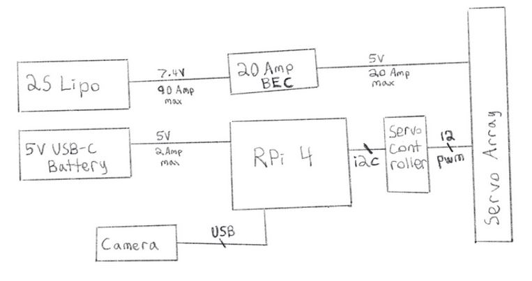
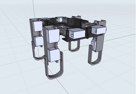
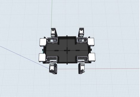
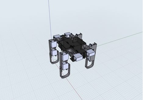
Our robotic dog had four legs, each of which was equipped with three servos: one for the shoulder, one for the upper part of the leg, and one for the lower part of the leg. Therefore, we made use of 12 servos in total. Most of the robot was 3D designed and 3D printed from scratch. We also used a servo controller with 16 channels to drive our servos. Our circuit also included a 2S Lipo battery and a 5V 20Amp BEC. Below are the electrical schematic and the 3D designs of our robot.
In order to control the servos, we used the Adafruit PCA9685 PWM Servo Library, which was compatible with our servo controller. We assigned each servo to the following channels on the PCA9685 board:
The library allowed us to adjust the angles (0-180 degrees) of the servos. Through trial and error, we managed to come up with the appropriate angles of the servos for a neutral standing position. For the other configurations, we encoded them not as the angles but as the offsets from the neutral position, which means that if we added the offset arrays to the configuration of the array for the neutral position element by element, we would get the actual angle arrays of those configurations. Our reason for encoding the configurations this way was because if any of the servos ended up breaking, we would only need to change the offset configuration of that servo specifically.
We also made a function to change the robot angle that took in the arguments of the offset array, the neutral position configuration array, and the number of steps we wanted the servo to make. We then calculated the appropriate increments associated with each servo depending on the number of steps. We then continually incremented the servo’s angles using the calculated increments until it achieved the configurations that we wanted.
We got inspiration from watching several Youtube videos of robotic dogs and came up with a walking algorithm for going forward, turning left, turning right, and going backwards.
In our walking algorithm we utilized the shoulders in addition to the upper and lower legs in order to let the robot lift its leg off the ground to some extent while bringing its legs forward. This had the effect of letting the robots bring its legs forward without imparting a backwards force on the robot. This allowed the robot to move forward instead of wobbling in place like we have seen in previous tests. For walking order, we chose to alternate between diagonal legs (i.e. the front-left and back-right leg come forward, while the front-right and back-left leg go back, and vice versa). We found that this pattern of movement seemed to be the most stable of all the walking algorithms we tried. The pictured animation below shows how the robot would walk forward.
Backing up was accomplished by implementing a similar pattern to forward, however the animation would be reflected over the vertical axis. Turning left and right was accomplished by implementing the forward algorithm on the legs on one side of the robot and the backward algorithm on the other legs.
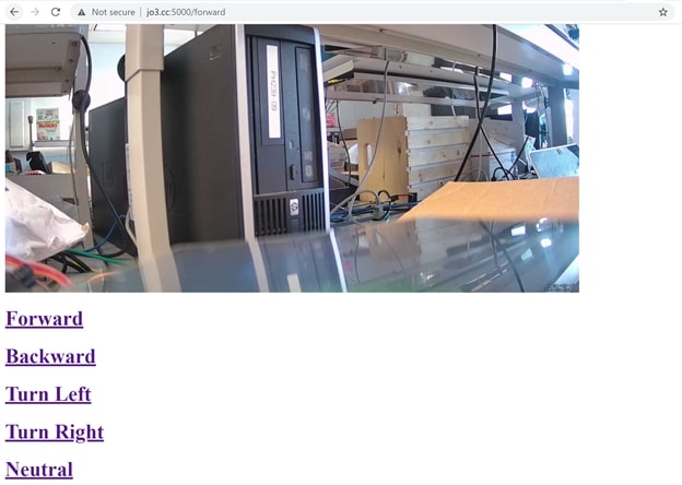
In order to implement our web server, we made use of the Flask library, which was a lightweight WSGI web application framework. We implemented a very basic website that had links that sent GET requests to different endpoints in the server. Each endpoint called a corresponding function for robot movement (i.e. the endpoint for forward would simply call our forward function and the forward function would handle all the servo manipulations).
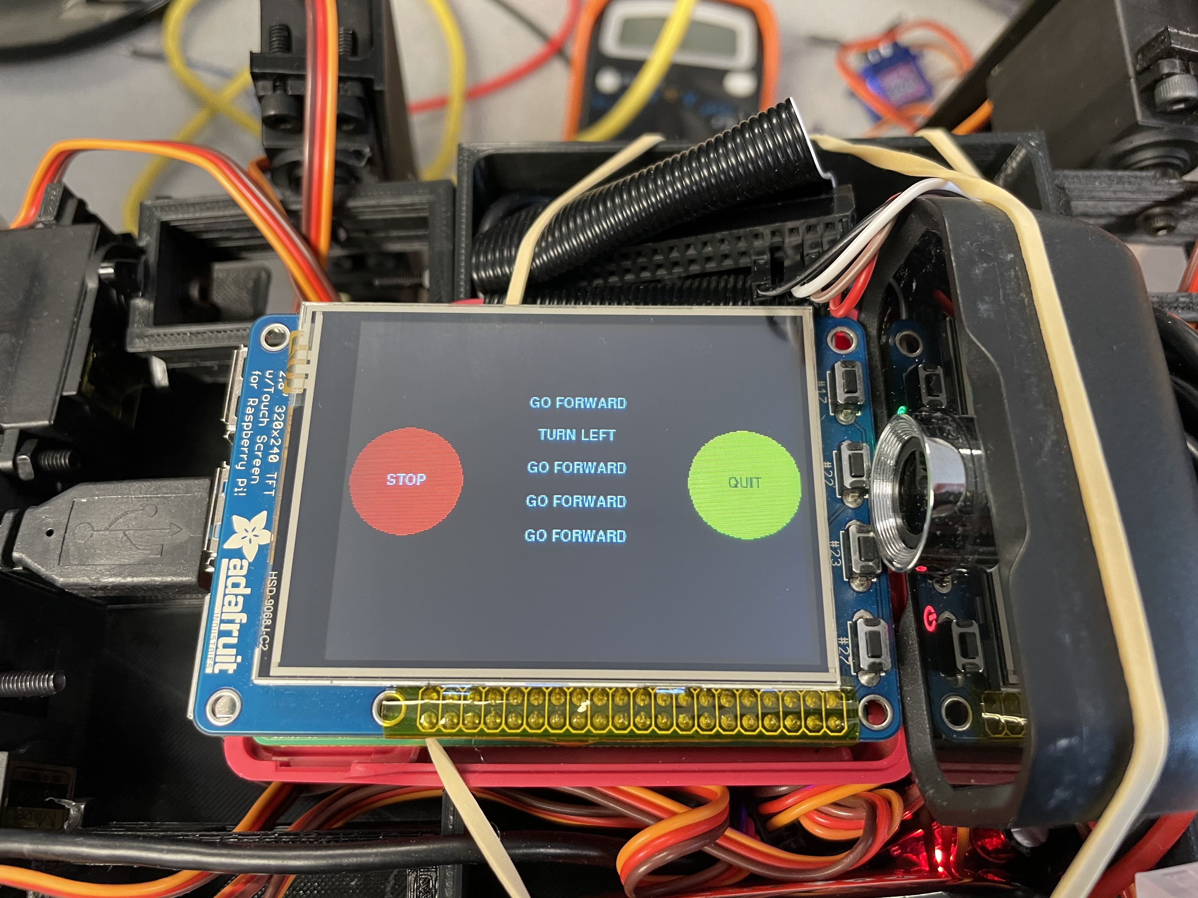
As for our GUI display on the PiTFT, we used the Pygame library to implement the feature. For the history display, we made use of a double ended queue of 5 elements. We implemented a panic stop button that, if pressed, would make the robot stop moving and continue with its movement after the resume button was pressed. We also implemented a quit button that helped quit the program if pressed.
Below is a high-level software/network architecture overview of our project:
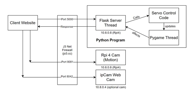
On boot up the raspberry pi automatically connects to an openvpn server running on a very cheap Linode VPS (price negligible). This VPS has a public IP address which the domain name jo3.cc points to. In order to make the raspberry pi’s services (ssh, webcam, web server) accessible to the public internet, port forwarding from the VPS was used via the Linux iptables tool. For example, since the vpn assigns the pi a static private ip of 10.8.0.8, we can execute these commands on the VPS to tell it to forward incoming requests on jo3.cc port 1111 to the raspberry pi’s ssh port (22):
echo "1" > /proc/sys/net/ipv4/ip_forward
iptables -t nat -A PREROUTING -p tcp --dport 1111 -j DNAT --to-destination 10.8.0.8:22
This way, on the public internet the pi could be accessed by doing:
ssh pi@jo3.cc -p 1111
In order to integrate a live feed web camera into our website we used motion-project webcam software and configured it in order for the pi to make a camera feed available on port 8081 on boot up. The flask web server / python program would then be on port 5000 and the website it serves up would make the client send a request to port 8081 to pull down the live feed. Ports 8081 and 5000 were exposed to the public in a similar fashion to port 1111.
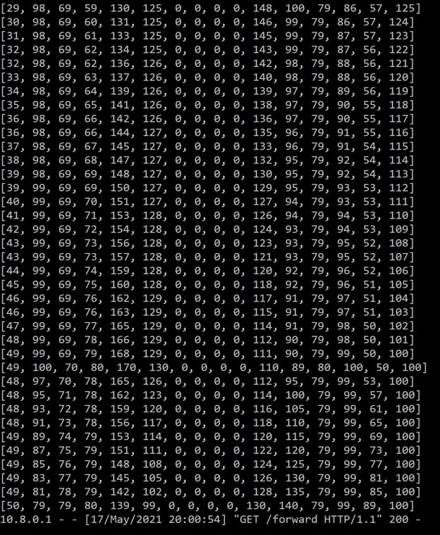
For debugging purposes, we tried disconnecting the robot so that it would not twist into bad positions if our code did not work and only printing out the angles of the servos onto the console.
In week 4, we also implemented a panic stop button so that we could stop the servos instead of having to disconnect the robot. We also included a history display on piTFT to make sure that the robot was moving according to how we remotely controlled it.
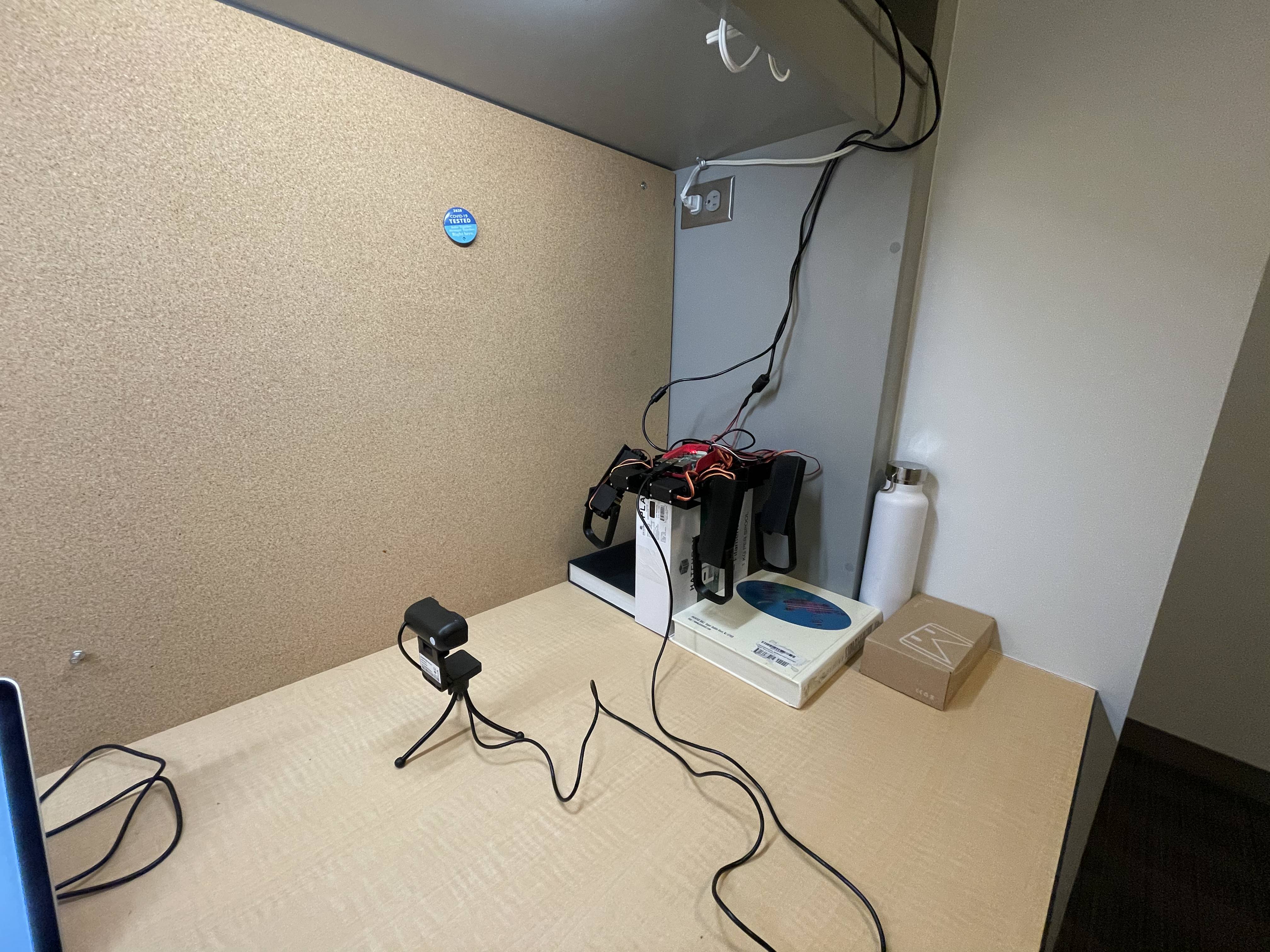
In order to facilitate working remotely, we set up the robot to be accessed and tested remotely by allowing ssh access and webcam access. A testing rig was set up to test robot legs without them touching the ground and the RPi and servo systems were hooked up to wall power to stay on without depleting batteries.
Our robot walked pretty decently on smooth surfaces. We could control the robot remotely using the web server. Our panic stop/resume and quit buttons worked as planned and the PiTFT displayed the correct history of the latest 5 movements of the robot. We met most of the goals outlined in the original project proposal.
Our project proved that we could make a robotic dog to walk well with the design we came up with (12 servos in total, each leg having 3 for the shoulder, the upper part and lower part of the leg). During the span of 4 weeks of trial and error, we realized that trying to make the robot walk without using the shoulder did not work. We also tried making our robot walk on the rug; however, it kept toppling over and was not walking properly. We also had issues with our 3D designs so we had to implement some axels to hold the robot together.
For future work, we are planning to improve 3D designs of the robot, improve the walking algorithm so that the robot can walk on various terrains, include computer vision, and sensors for obstacle avoidance.
| Part Name | Quantity | Link | Price |
|---|---|---|---|
| Lab Kits (RPi 4, PiTFT, Power Bank, SD Card) | N/A | Borrowed from Professor | $0 |
| HK15138 Servos | 4 | Link | $44 |
| 5V 20Amp BEC | 1 | Link | $24 |
| 2S Lipo battery | 1 | Link | $12 |
| Servo Controller | 1 | Link | $5 |
| Wires, Connectors | N/A | Borrowed from Professor | $5 |
| 3D printed parts | N/A | From Joseph's 3D Printer | $2 |
| PiCam | 1 | Borrowed from Professor | $8 |
| Total | $100 |
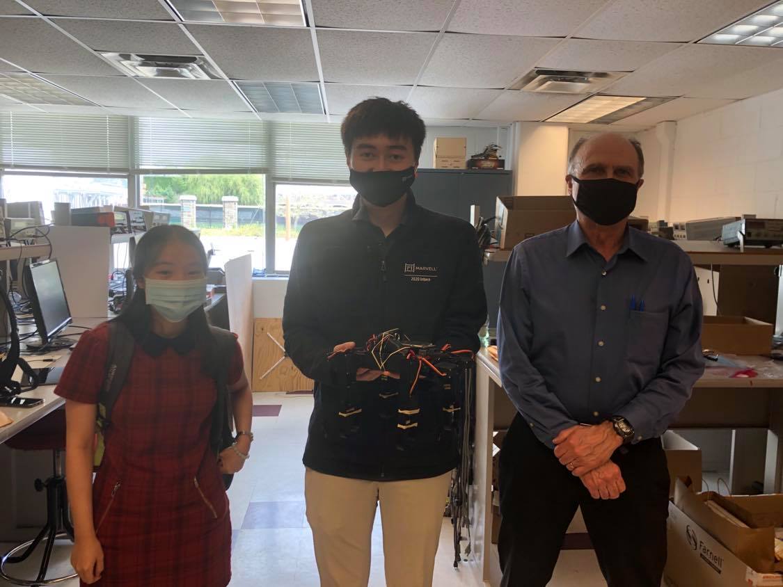
Joseph 3D designed and 3D printed the robot's parts, put together the hardware components, and came up with the walking algorithm. Abby implemented the PiTFT display and designed the website. We did peer programming and worked on most of the software components together. Here is a photo of our team taken with Professor Skovira!
Here is a photo of our team taken with Professor Skovira!