Introduction
Learn about the project as a whole. High level description of the build.
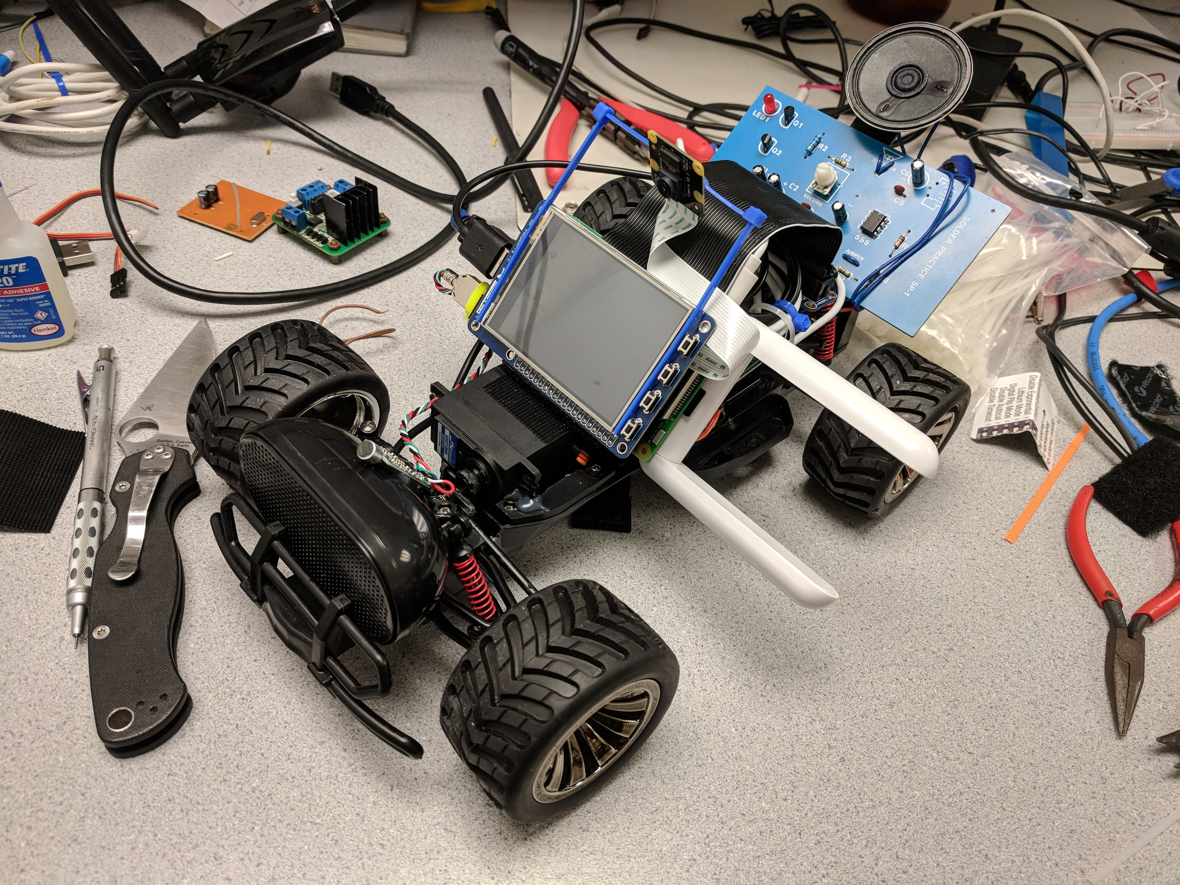
Raspberry Pi Teleprescence Robot
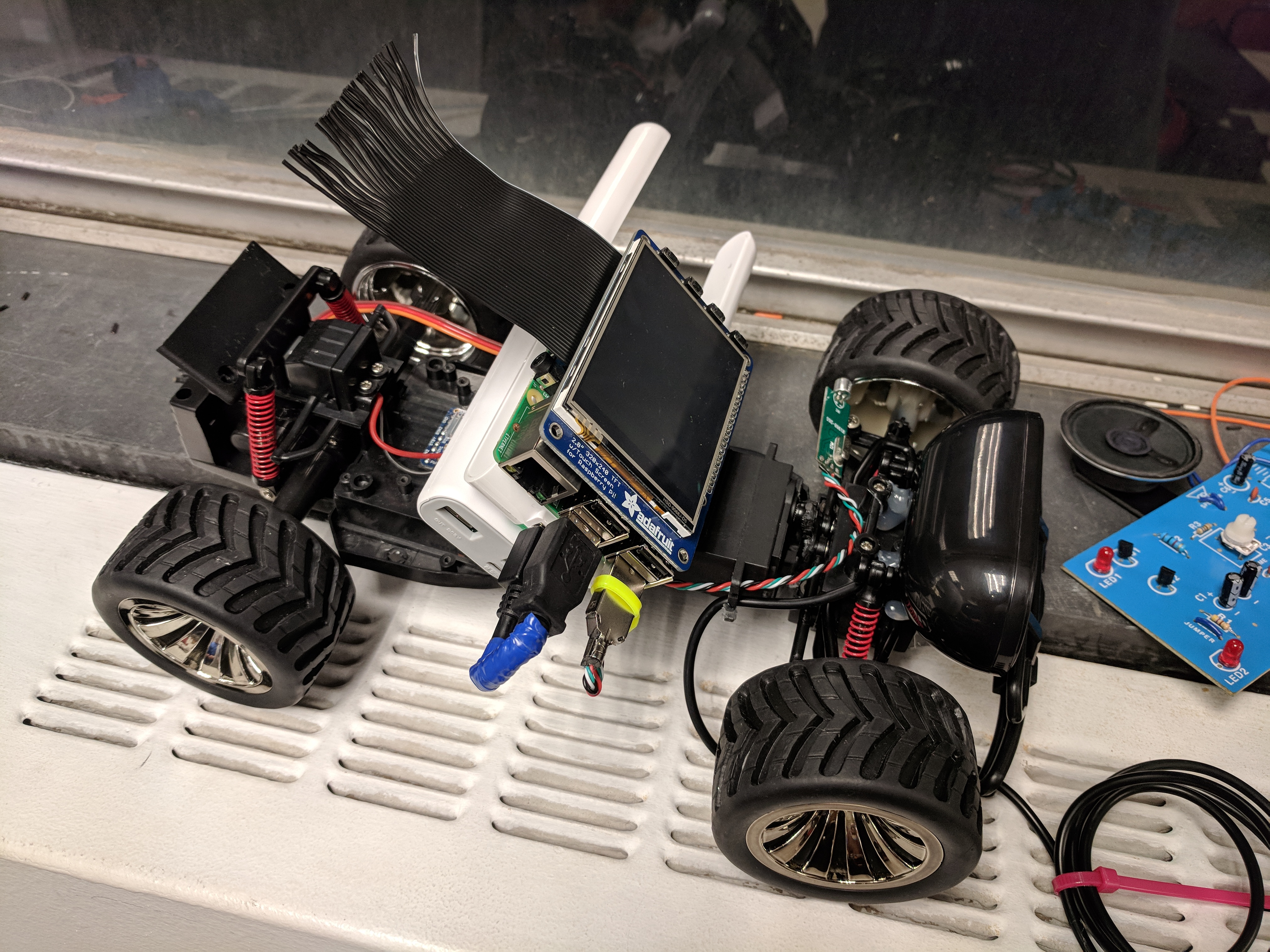
This highly modified RC car can be controlled over a wireless network and streams back live video to its pilot. An onboard TFT display, microphone, and speakers allow for virtual communication and presence. The 555-timer siren and warning LEDs can be switched on and off to catch people's attention or perform traffic stops on pets and small humans.
Learn about the project as a whole. High level description of the build.
Learn about the specifics of the project. Dive into the dense "nitty-gritty" of it all.
How did the project perform? What worked and what did not work?
Take a step back and evaluate the end result of the project in more general terms.
We decided to build a telepresence robot knowing that the project would require a good mix of hardware and software design, and plenty of time hands-on building the project and debugging. Our ambitions were met with many pitfalls and pivot points, but in the end we succeeded on almost all fronts and created a tightly integrated platform with impressively low control and video streaming latency and a plethora of sensory devices and features. Read on to live vicariously through our successes and find schadenfreude in our failings.
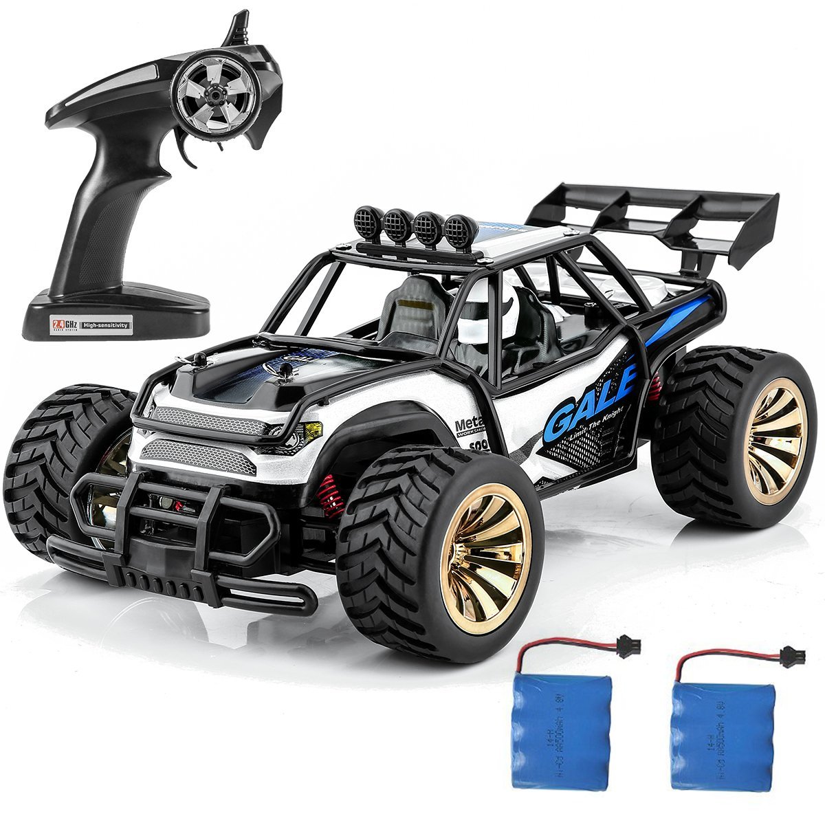
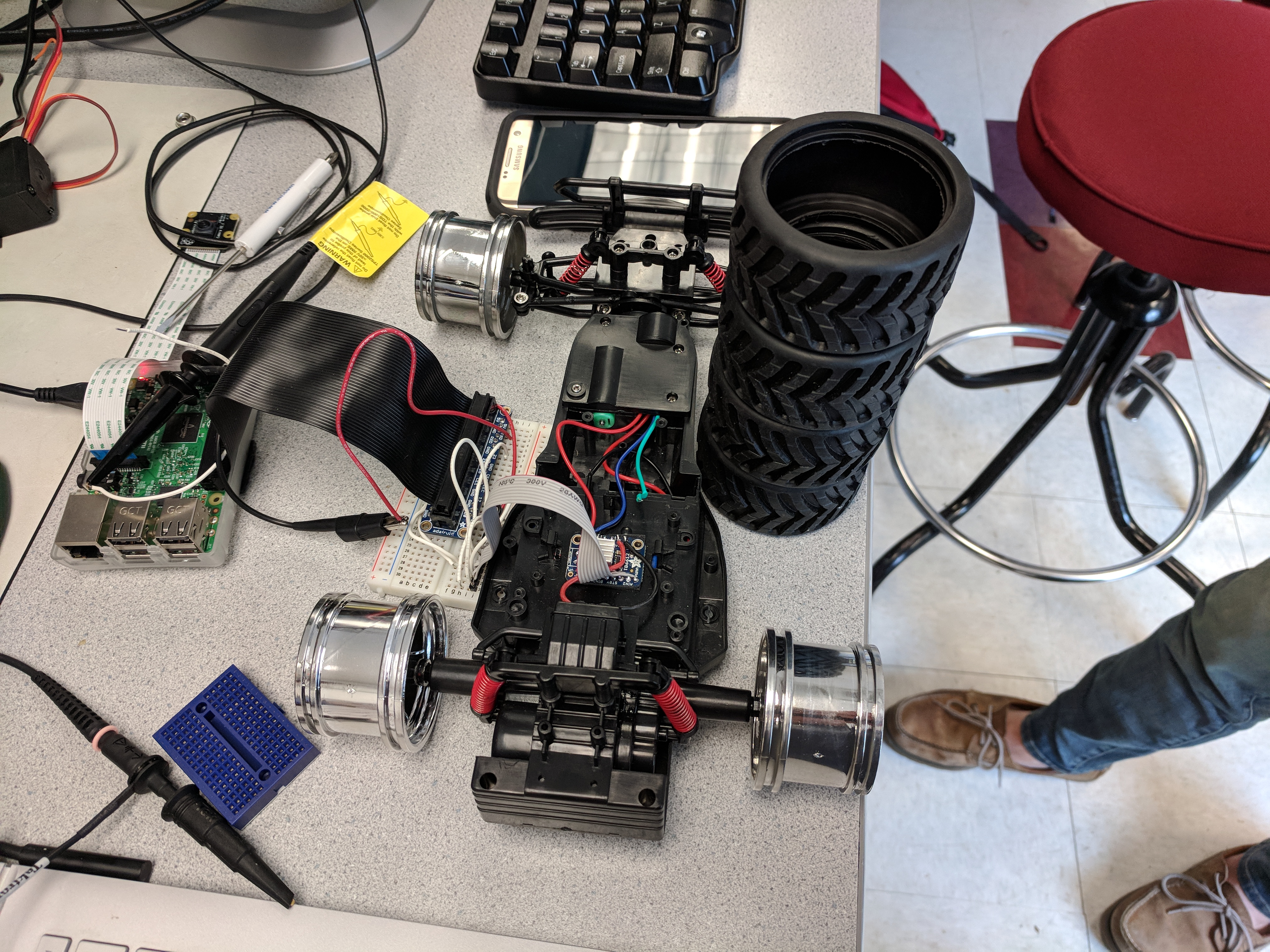
Our robot is built around a stripped-down remote control car.
Or whats left of it
Description
Because our self driving neural network is still learning
Lights make everything better; even if it is a bunch of tiny ones
Smile
Because the onboard wifi has a max range of 3 feet
Its never a party without music.
When 1 Amp is not quite enough
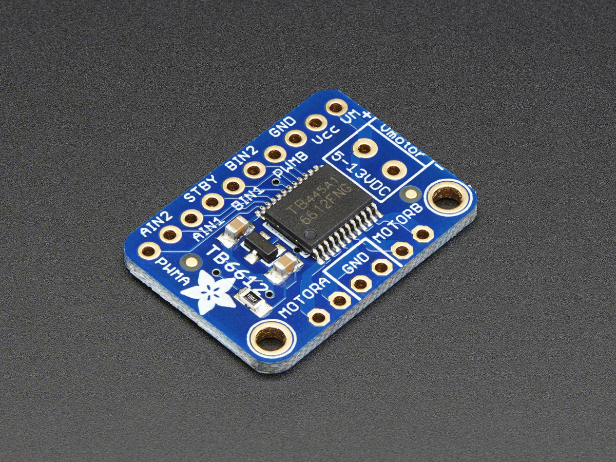
A motor controller that does not even drive a motor
Our robot chassis started as a generic 1:16 scale RC car from Amazon. The first thing we did was strip off all of the electronics and extra body trim from the vehicle to fit in our custom components and electronics. We then built on top of the bare chassis with a new steering system, motor controllers to allow the RPi to control movement and signaling, and mounting points for other electronics. For more information about the RC Car, see here: More Information
The car included a stock steering system that surpringly was not a servo at all, but rather a motor with a slip linkage that drove the wheels to full lock in either direction. We wanted greater precision while driving so we stripped out the entire mechanism and replaced it with a custom servo and linkage that gave us granular steering precision. Because we'd be using hot glue to install the new servo into the car, we were careful to center the servo between its end stops before installing the servo horn. After installing the new mechanism a bit more trimming of plastic was necessary to allow for unobstructed movement to full lock in either direction.
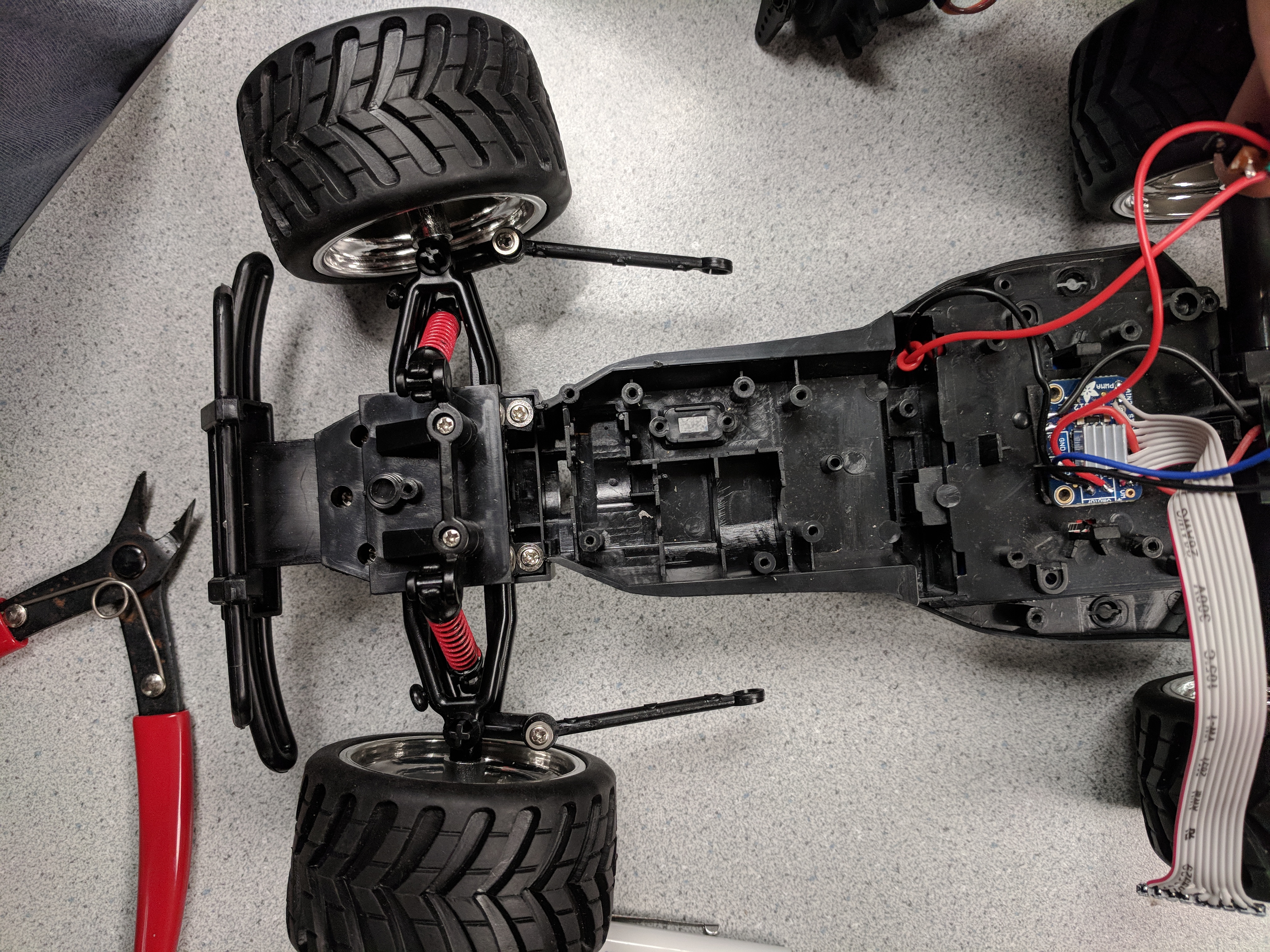 The stock steering mechanism stripped out
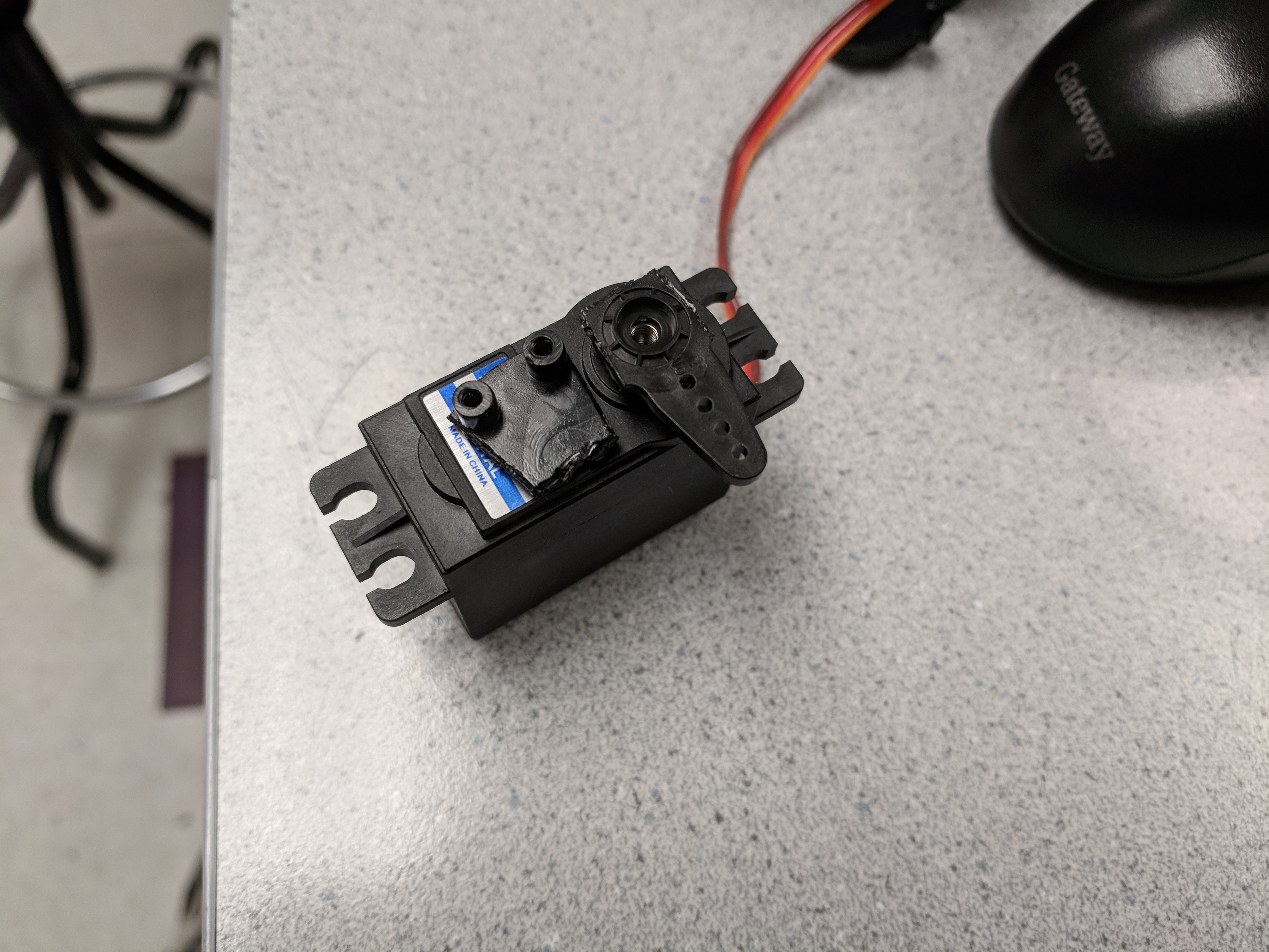 Cutting down parts to create a new linkage
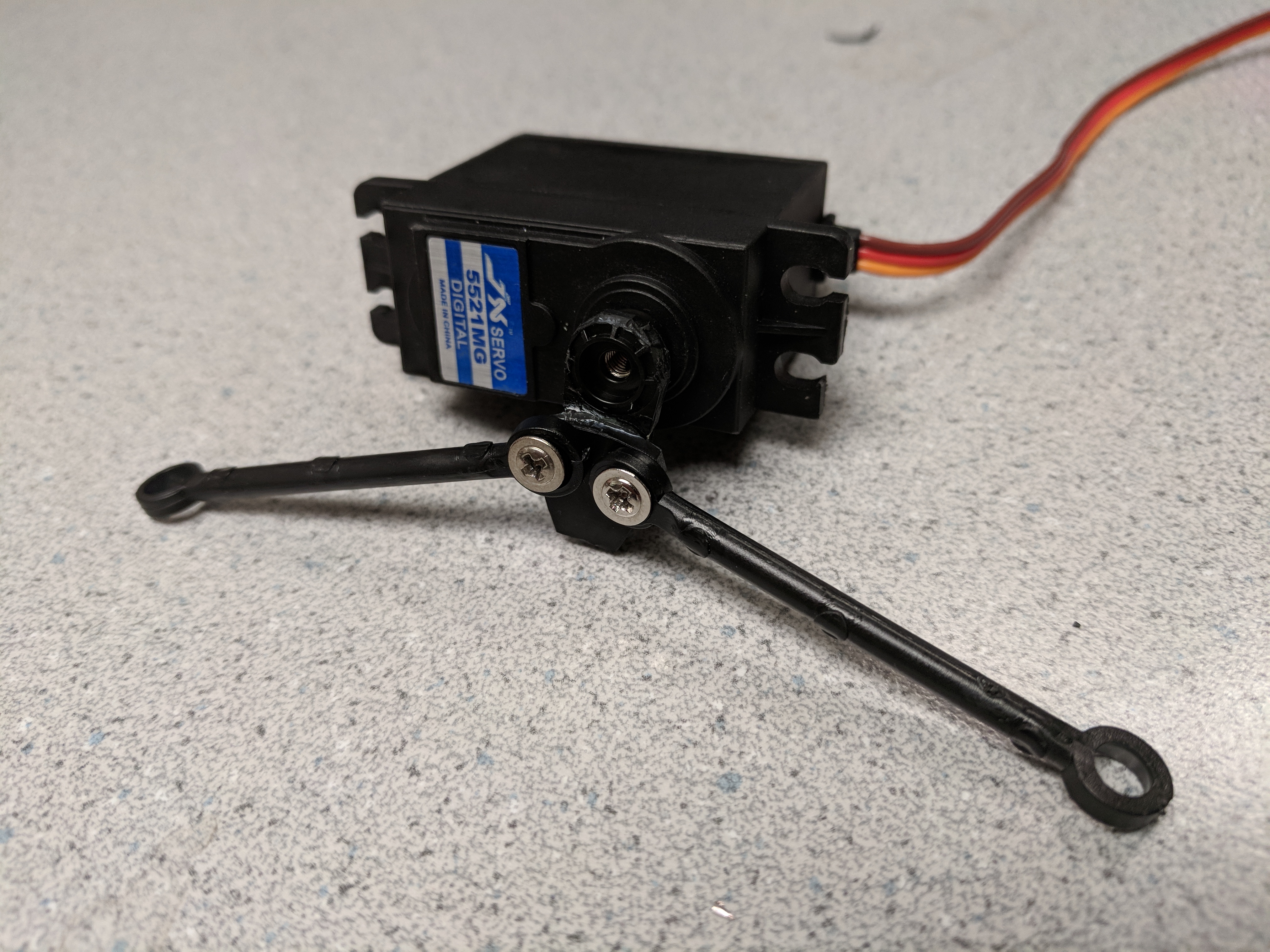 New mechanism ready for install
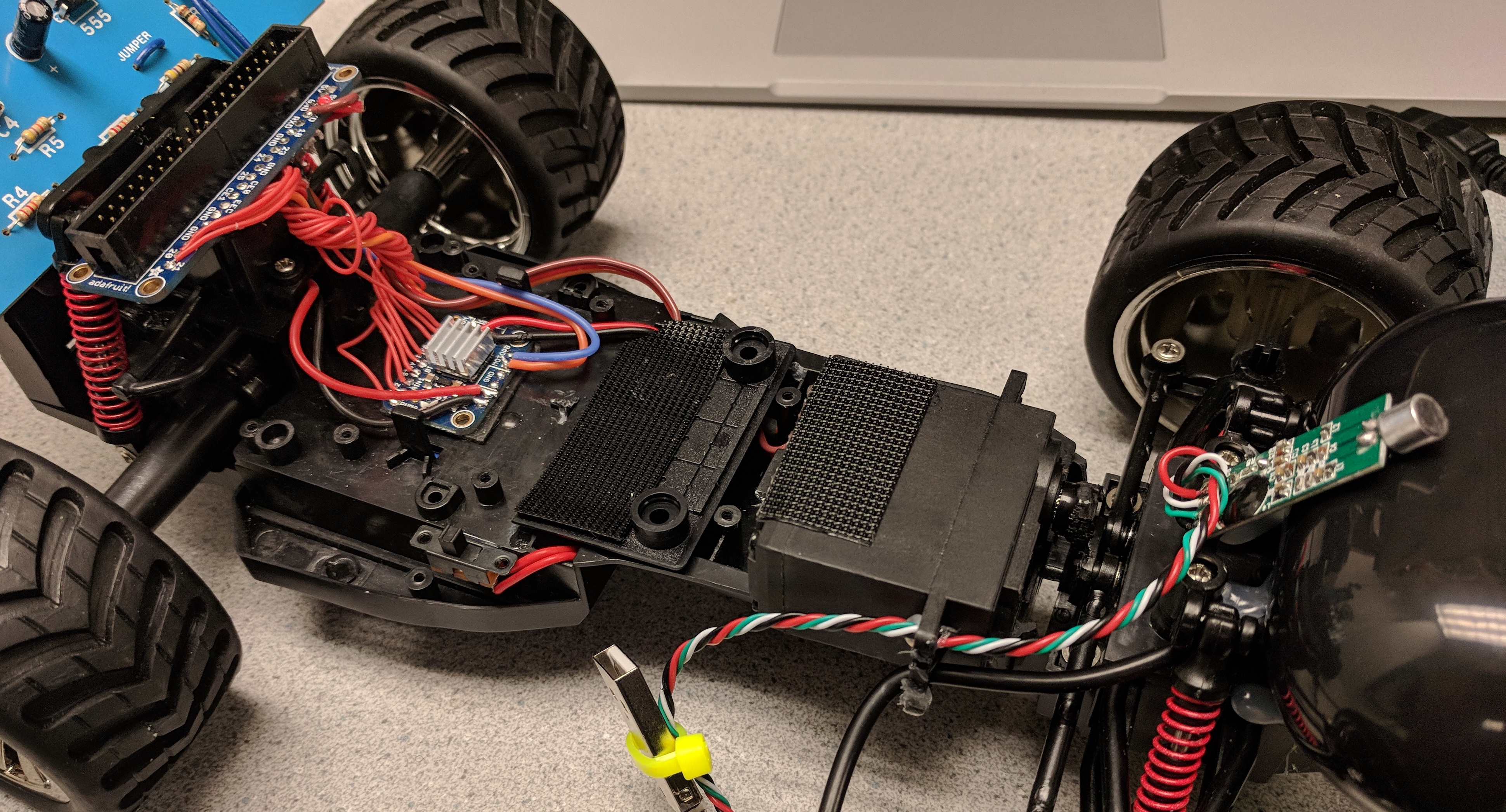
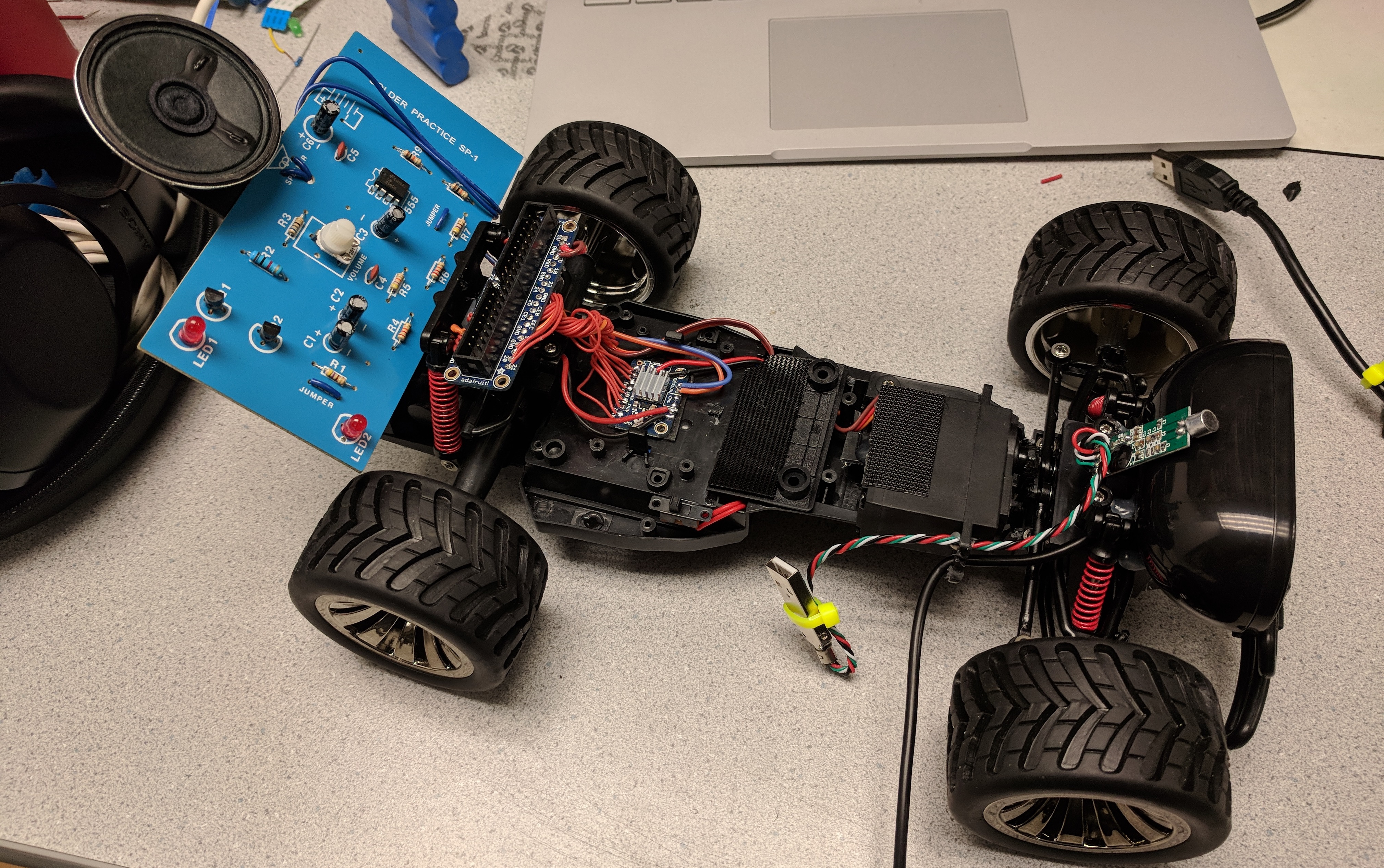
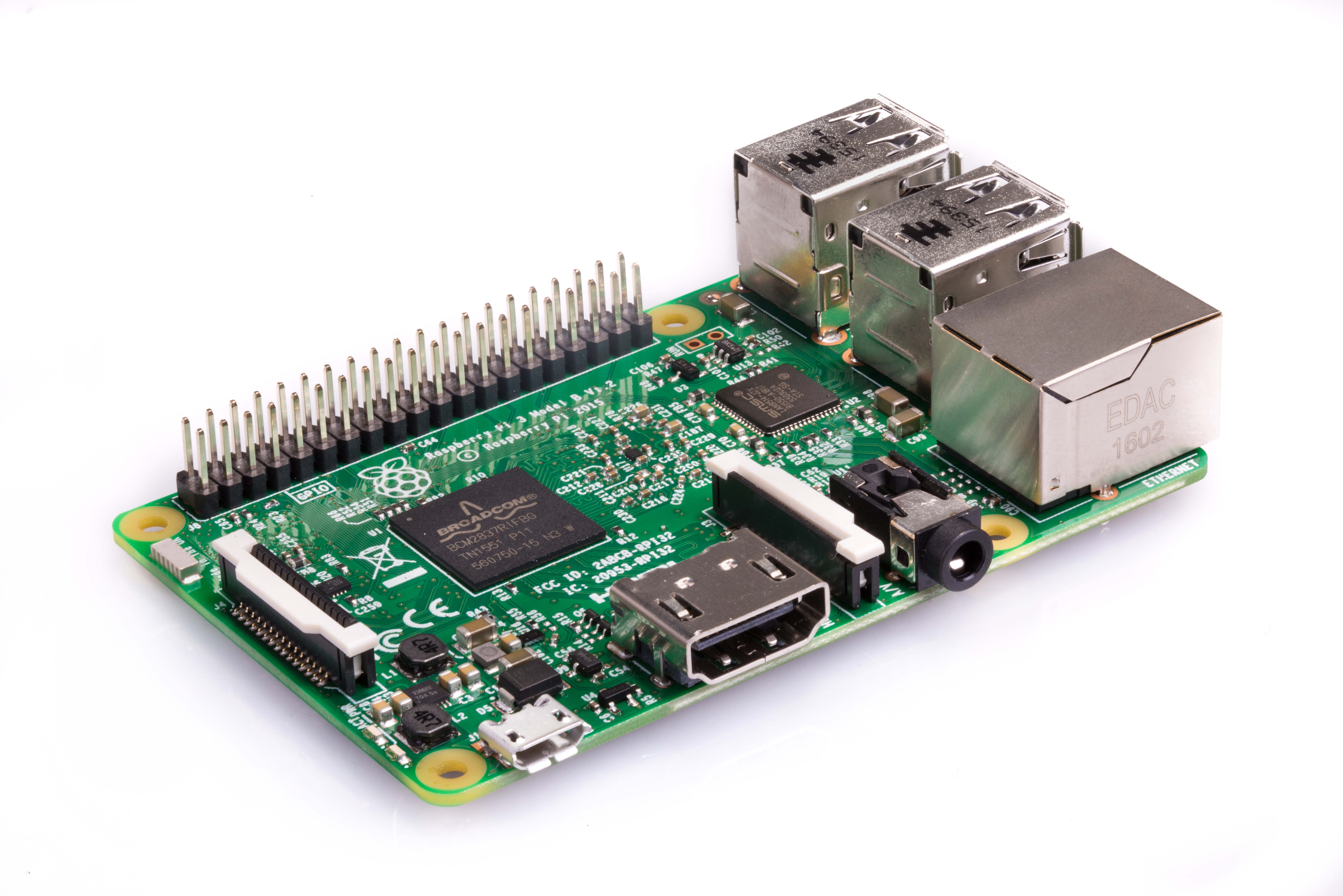
The core of our project is the computer that runs the whole show. We used a Raspberry Pi 3 Model B running Raspbian Linux (based on debian) to host the robot's webserver, control all peripheral electronics, and communicate with the servo and motor controllers over the Pi's GPIO using PWM signals. For more information about the device, see here: More Information
uv4l is a set of packages similar to Apache which can host webpages. However, unlike Apache it is designed around web streaming services. For the backend, we had to setup uv4l with the proper settings to establish a video stream. This is discussed more in the section on the raspicam. uv4l serves a default webpage on port 8080. This webpage includes all of the video streams as well as examples of peer to peer connections for video conferences. Once the backend was running, and uv4l was serving our video stream, we could move to the webpage. In addition to the default server, uv4l can also host a user defined webpage. This is were we developed the html and js required for our project.
The Pi includes a number of onboard general purpose IO pins which we made use of for controlling parts of the car that didn't interface over USB. We used the python RPi.GPIO library to generate PWM signals to XXX
In order for the user to interact with the rest of the world, they need to be able to move the car around the world freely. As discussed in the hardware section, we hacked apart an existing car framework to use our own PWM signals, But we still had to send these signals and generate them.
In order to send commands from the user to the car, we had to find a way for the client to communicate with the web server. In order to decrease latency and improve the driveability of the car, we used websockets. Although the is no way to access true computer sockets in javascript, websockets provide a nice framework which is quite similar. At the client side, we simply open a connection on a specific port and are able to send data in json form. On the backend, we used a python package called websockets. The use of this package forced us to use python3 since it is only supported by python3. This was not much of an issue but is worth not. In python, we opened a websocket on the same port as on the client side and wait to read data. When a new line of data is read in, it is simply printed to the console. This might seem useless, but it is because the websocket control is a subprocess of the general control program, and printing out the information is how we send data between the processes.
Initially, we simply detected arrow key presses to control the car. We chose to expand this and use a gamepad to allow for easier control of the car. Almost all browsers have native support for gamepads. Using the gamepad library, we were able to detect when a gamepad is connected, and poll various buttons and sticks to establish control signals.

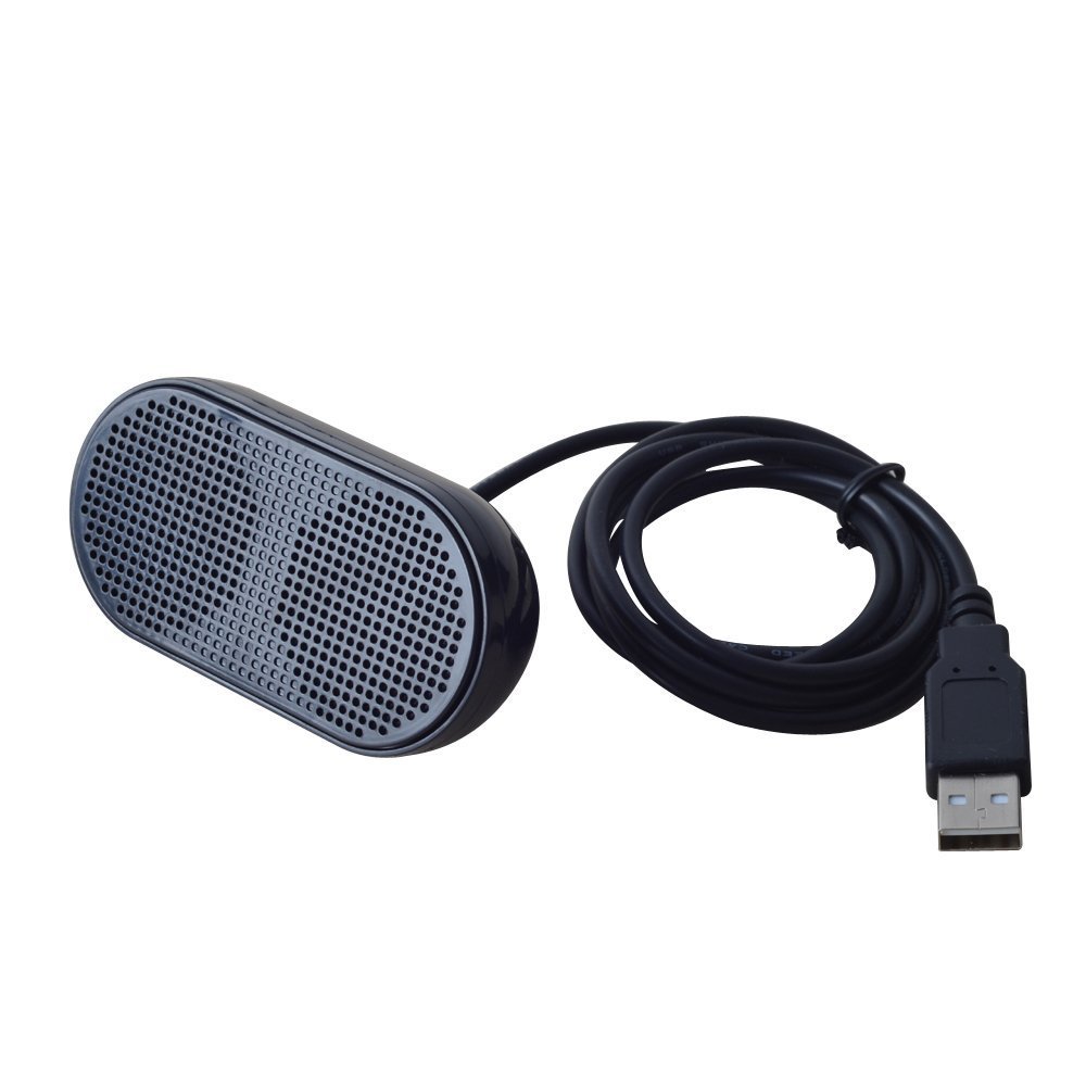
This USB speaker allows us to play songs on the robot, or speak to people remotely. For more information about the speaker, see here: More Information
This was one of the very few devices on our robot to work almost out of the box, after selecting the right output device in AlsaMixer.
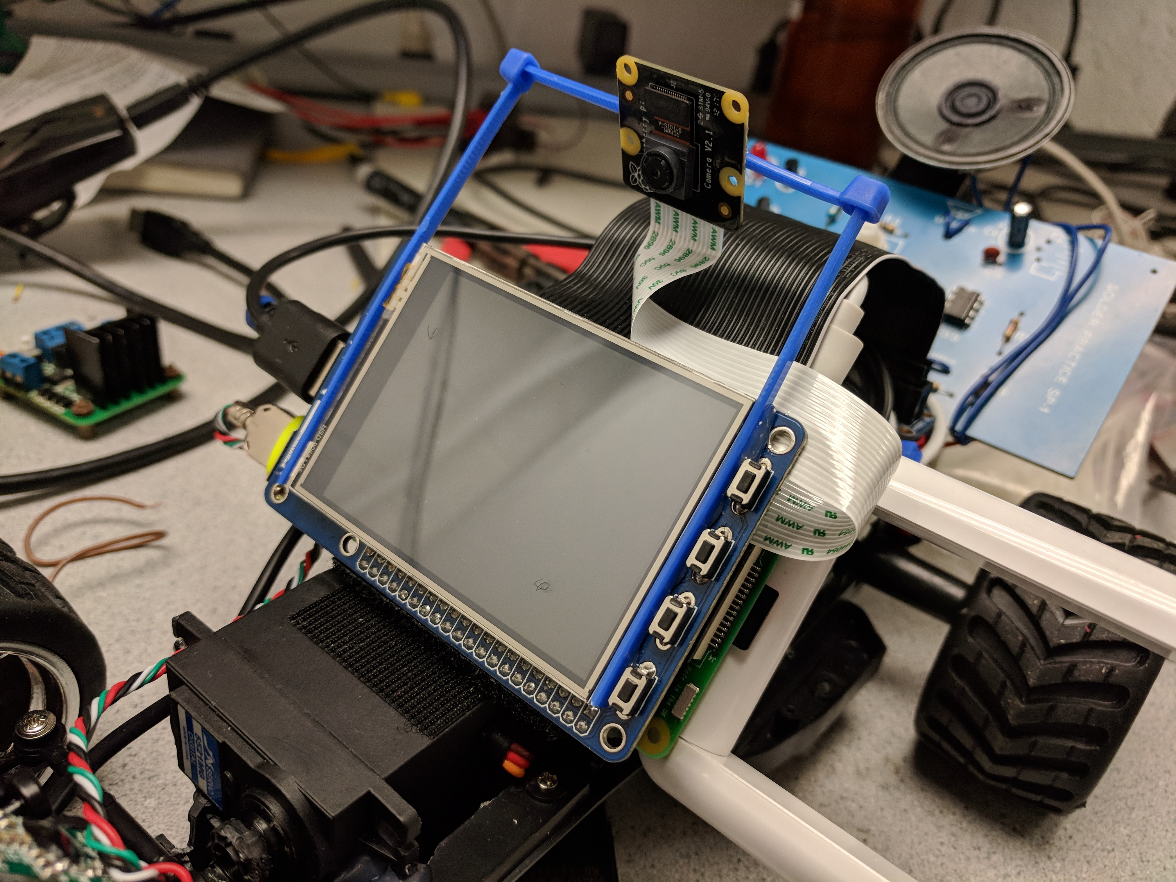
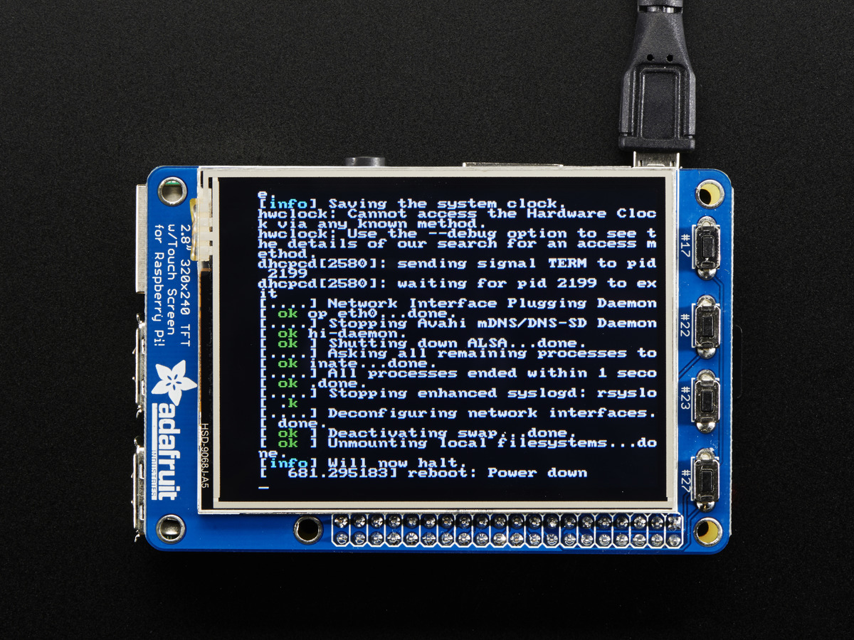
This PiTFT Plus display is our main method of displaying images and video feeds to people who see the robot in operation. When in telepresence mode, the TFT shows the webcam feed of the person piloting the robot. It neatly stacks on top of the Raspberry Pi for easy integration. For more information about the device, see here: More Information
The PiTFT is developed by Adafruit, and has a large amount of documentation on how to get it working. Unfortunately, newer releases of the Raspbian kernel no longer work with the setup scripts provided by Adafruit. Because of this, we went through a sequence of steps outlined in Lab 1 to get the PiTFT working with our linux distribution. For brevity, I will leave the specific details to the Lab 1 handout.
Following Lab 1, the Raspberry Pi boots to a command line on the PiTFT. In order to display a video feed, we wanted to have the desktop available to run certain applications. While applications can be launched from the command line, it does not always operate as expected. In order to get the Pi to boot to the desktop on the PiTFT, we downloaded a bash script from Adafruit's repo and ran the setup. Previously, we stated that this does not work, however, it does accomplish a large portion of the setup. After running this script and choosing the boot to desktop option, we re-traced through Lab 1 to make sure the remaining setup was complete. At certain sections, you must make sure that you do not revert the changes to files and continue booting to the command line. Once this setup was complete, we rebooted the Pi, and the desktop was displayed on the PiTFT. We waited until the later parts of our project to do this since it is quite hard to use the desktop on the PiTFT. We were still able to utilize ssh, however, because we doing web development, the desktop was a valuable resource in debugging.

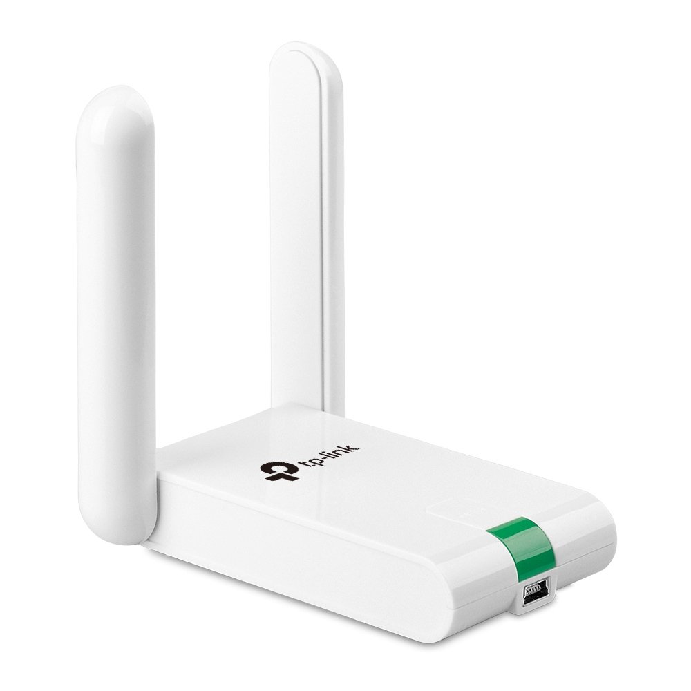
For improved performance and reliability over the onboard Raspberry Pi WiFi, we used a USB WiFi dongle with larger antennas. For more information about the device, see here: More Information
The wifi dongle we used is compatible with linux by default (a lot of wifi dongles require extra drivers). Because of this, there was not much required setup. After connnecting the dongle through USB connection, we made sure the device was detected using the commands dmesg and lsusb. Next, we checked the network connectivity using the command ifconfig. With the dongle connected, wlan1 was displayed in addition to wlan0. With two network devices, we encounterd issues with the Pi switching between the wifi dongle and the onboard wifi chip. In order to default to the dongle, we ran the command sudo ifconfig wlan0 down. This shuts down wlan0 until it is either brought back up, or the Pi is rebooted. Eventually we added this to .bashrc so always default to the wifi dongle even on startup.
In order to host a webserver and remotely operate the car, the onboard Pi had to be connected to the internet. Typically, servers have ethernet. Since we wanted to be able to drive the car aronund, a tethered connection was not ideal. Although it is possible to host websites over wifi, it is not ideal. We began by connecting to RedRover, and just using the Pi's IP address to connect to the website. The RedRover network is not really designed for this use case, and it likely one worked because we were on the same access point. Moving to another part of the building might have easily failed as RedRover is composed of a bunch of sub-networks.
Initially, we wanted to use webcams to stream video, however this requires a secure webserver; ssl. We hacked away for the better part of a day trying to whitelist self signed certificates in google chrome. When this failed miserably, we contacted IT to get their opinion on our problem. IT ended up setting up a hostname and static IP for our Pi on the lab's network. This also required a router to be installed in the lab using the lab's ethernet. This is where the dongle comes in. In order for them to setup the hostname and IP, we had to provide the MAC address of the dongle. Each network device has a unique MAC address, therefore there was one for the dongle and one for the onboard wifi chip. Once IT completed their work, and the Pi was connected to the network, the specified IP was acquired, and we could host the website at the provided hostname.

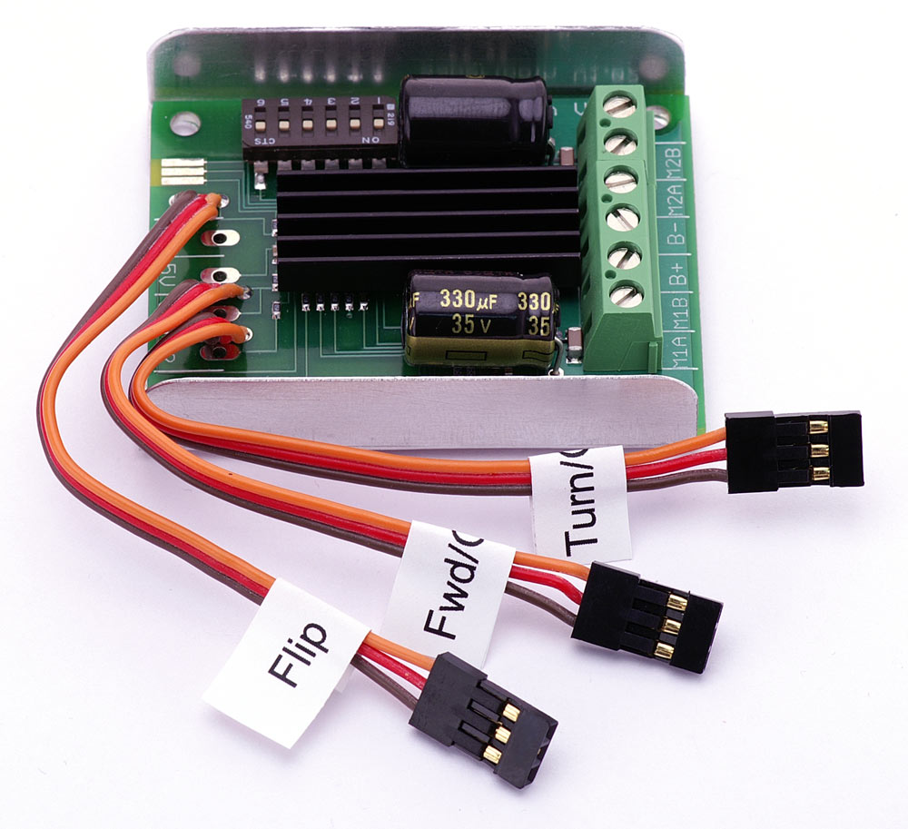
This is the initial motor driver we used to control the car. However it became apparent after testing the car on the ground that the driver quickly started to overheat and hit its current limit, so it is now relegated to turning on and off the siren board. For more information about the device, see here: More Information
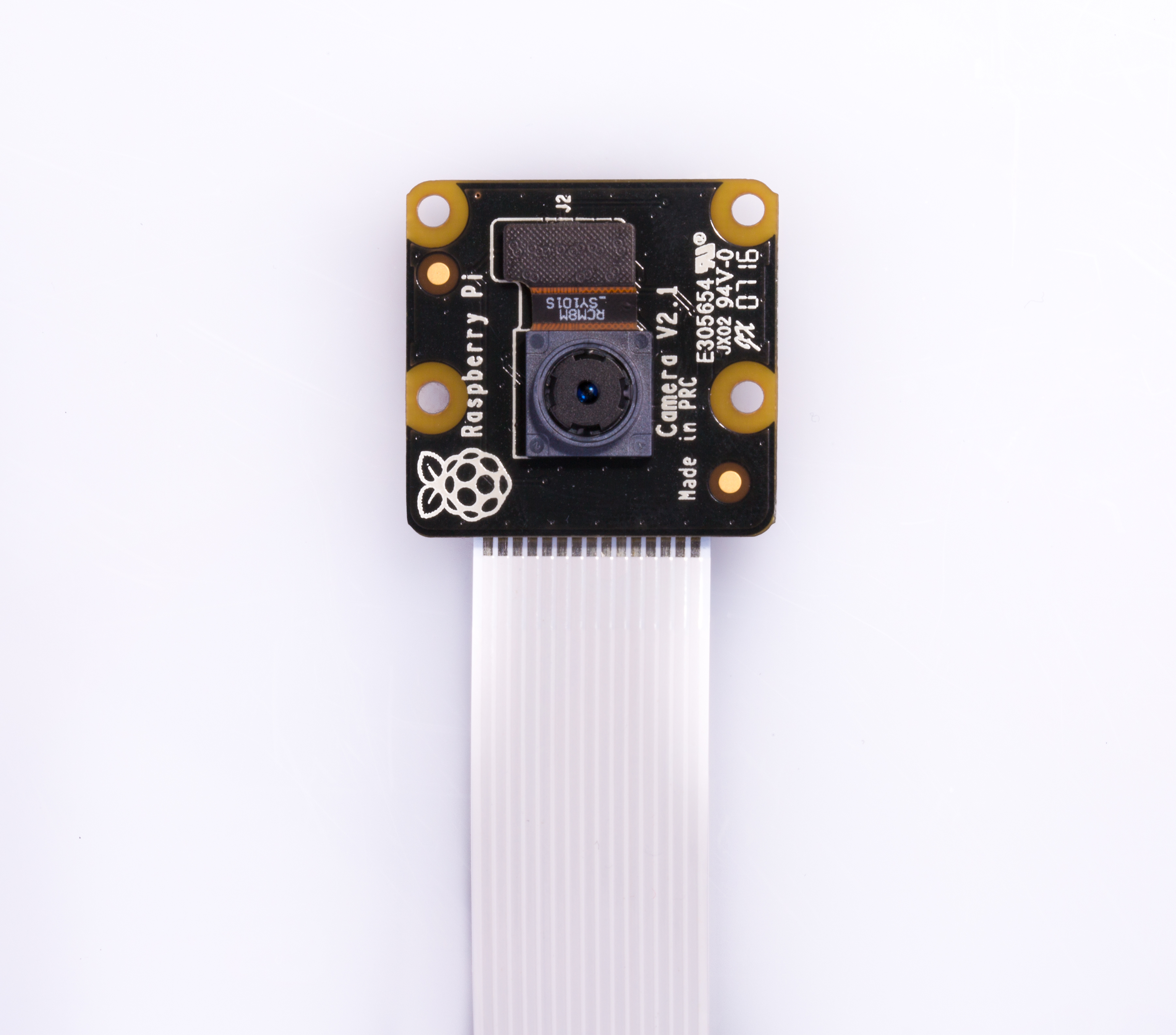
Thankfully, PiCam's are designed to work with Raspberry Pi's out of the box. After connecting the camera to the camera port, we enabled the camera in the Pi's configuration settings. Following this, we were able to test the operation using the program raspistill.
uv4l can operate using both a USB webcam stream as well as a raspicam. The framework was largely developed for use on a Raspberry Pi, and therefore, the raspicam was a natural video method. In uv4l, switching from a USB webcam to the raspicam is a simple as changing the .conf file to take its input from the raspicam. After changing the appropriate settings and restarting the server, we were finally able to see a video stream at http://raspi-ip:8080/stream/video.mjpeg. Now that we had a stream, we could easily incorporate it into a webpage.
This is the initial motor driver we used to control the car. However it became apparent after testing the car on the ground that the driver quickly started to overheat and hit its current limit, so it is now relegated to turning on and off the siren board. For more information about the device, see here: More Information

A lot of consideration had to go into the setup and wiring of the PIC32. Trying to make an autonomous drone, the PIC32 must be attached to the drone and be able to operate on whatever power is provided. I went through a couple different design choices and ultimately settled on a solution which works well. In addition to the physical setup, I had to develop code which would work in the new environment. For more information about the device, see here: More Information

Using websockets to send control commands from the user to the RC car worked quite well. The latency between the input of the command and the movement of the robot is almost always well under a quarter of a second. The video stream while being slightly slower is still quite responnsive. Decreasing the resolutionn improved the performance, and the image quality is still good enough to drive. All together, these components allow the car to be easily driveable from the website using the video feed.
The video stream to display the user on the PiTFT was not as responsive as we would like. Unfortunately, we only had one wifi dongle, and the onboard wifi of the second Pi was not good enough to provide reliable video streams even at a low resolution.

Our project went through a great number of itertions during its development. While the final project was not quite what we expected, we were happy with the results. The first and most important thing we learned is that web development is diffcult and is even hard to hack a solution for. With only client access to the network, it is very difficult to develop web applications that can be used anywhere. All together, we felt the project was a good way to utilized the Raspberry Pi in a fully embedded system with both hardware and software components.

| Part | Unit Cost | Number | Total Cost |
|---|---|---|---|
| Extra Raspberry PI | 35.00 | 1 | 35.00 |
| RC Car | 20.00 | 1 | 20.00 |
| Speaker | 5.00 | 4 | 5.00 |
| 60.00 | |||
Most of the parts we used for this project were scrounged. For example, the motor controller was found in the high voltage lab. The microphone was taken from a broken frame and re-soldered.
Most of the project was completed with both Ryan and Adam working together. In general, Adam focused on the hardware aspects regarding the RC Car while Ryan focused on the software and the wb interface.