Autonomous Tracking Robot
Yanling Wu(yw996) | Ta Wei Yeh(ty359)
Tracking Robotic Car
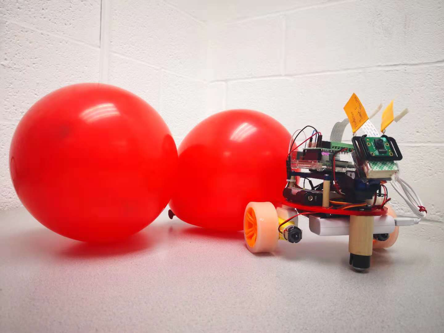
Robotic car can track a falling balloon and pop it.
An autonomous balloon tracking vehicle capable of tracking a balloon and terminating it.
Based on Raspberry Pi, we create a tracking robot that can track a falling red balloon and try to pop the balloon before it lands. In order to recognize the balloon, we implemented the color detection by OpenCV. The precise and stable locomotive of the robot, which includes camera tilt kit and two DC motors, has been controlled via PID algorithm. Besides, leveraging python’s multiprocessor modules tremendously decreases image processing latency in real-time.
Since we only have one Pi camera, we couldn’t measure the distance from the method of two camera. Our solution is to keep the balloon on the center of the image as possible. Therefore, the area would represent as the distance between the balloon and the robot. The Y axis differential would be the rotation error. And the X axis differential would be the tilt error. Consequently, our robot should require the accurate recognition on the balloon.
To accomplish the project, we have divided it into several smaller tasks and combine them in the end. In general, there are two parts which are hardware and software. And they have different tasks to be tackled in the following introduction.
`The body of the car.
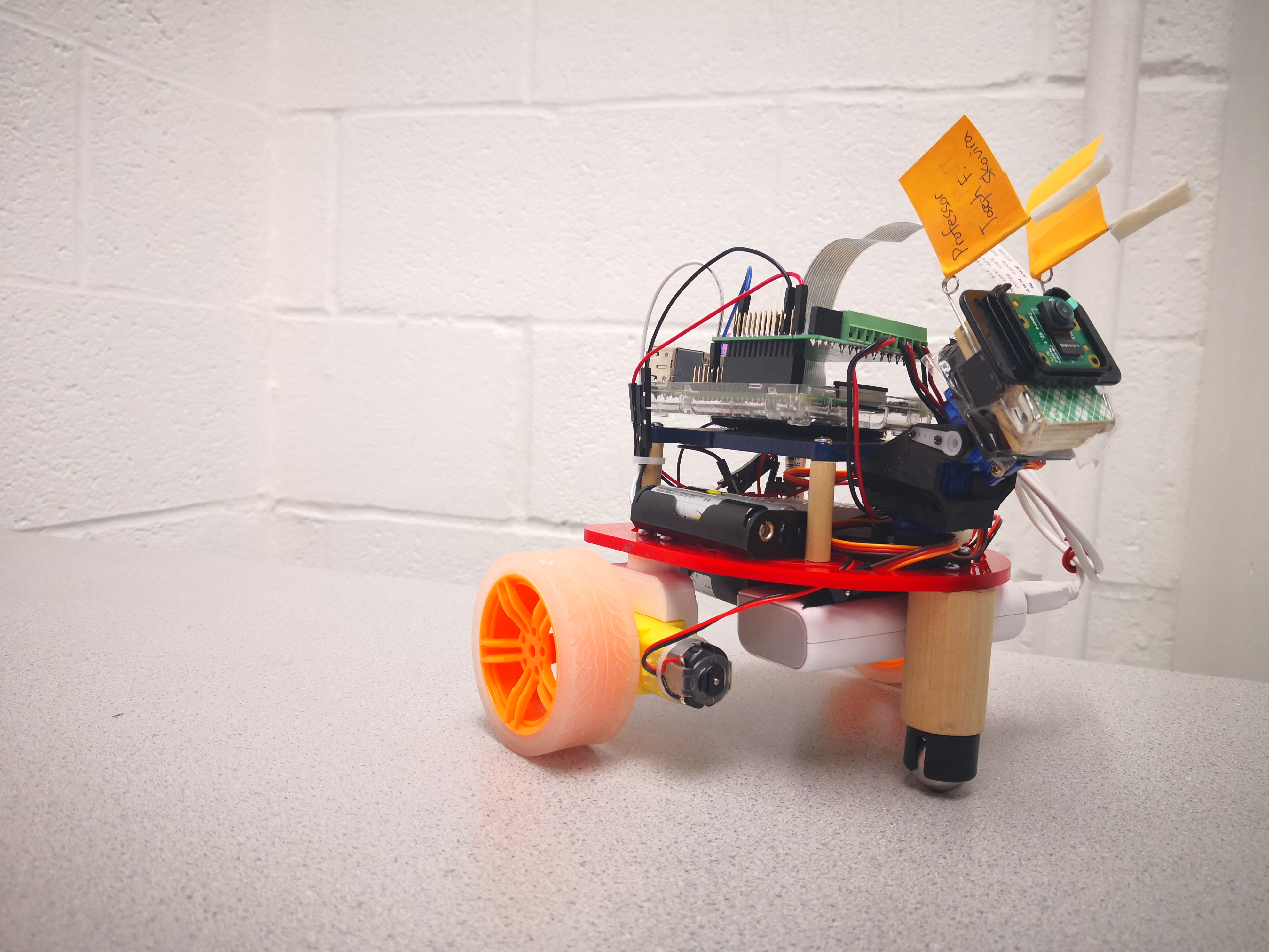
Our robot, in short, is a differential drive vehicle with a Pi camera on it. Therefore, we would need two motors to drive the robot and a ball bearing keep it balancing. We also need robot frames to hold everything up. Here’s our shot of the robot.
Everything is in placed from the previous lab section, except the motor brackets. We self-designed the motor brackets using Solidworks. After several simulation and testing, we would be able to fit the motor with the robot frame properly.
Due to the speed limit, the Parallax continuous rotation servo is replaced by TT DC Gearbox Motor with higher rpm (200RPM). However, unlike Parallax continuous rotation servo, we can’t control the DC motor with PWM commands. The DC motor is powered from 3VDC to 6VDC. The higher voltage, the faster it goes. As a result, we bought a motor driver – “RasPi Robot Board v3”. It could transform the PWM signal into voltage level and thereby control our DC motors.
The driver is best required with 9VDC input to supply the motors, although a motor only required 5DV input. This is because if the voltage input is lower than 9VDC, the driver could be malfunctioning. Any unexpected result would come out of nowhere and it’s a painful bug to be realized when developing the robot.
Also, keep in mind that although 6VDC is its maximum speed limit, it is when the DC motor is unloaded. Moreover, the higher voltage it required, the more current it would need as well. In terms of that means it’s more power consumption than normal, and we need to keep changing the batteries for stable speed outcome and high rpm.
The organ of the car.
Our object recognition algorithm could detect the red objects videoed by the Pi camera and calculate the center position. The usage of the OpenCV library makes the algorithm easy to implement. First of all, we install the openCV library into our Raspberry Pi. There are some ways to install the openCV library. The easiest and direct method is to run the command “sudo apt-get install libopencv-dev python-opencv” in the command prompt, which can help us to save several hours to compile the openCV. The version of our installed openCV is '2.4.9.1'. After installing the openCV successfully, we need to assemble the Pi camera onto the R-Pi and set it up in configuration of R-Pi. As for the design of the recognition algorithm, it can be broken up into following parts.
When balloon quickly moved and get rid of the range that the camera can video, the servo of camera will not know how to move and it will be stuck. To solve this problem, we create the prediction algorithm. Prediction Algorithm is to make the servo move at the speed that is slower than the original speed but the same direction. “Original speed” is the speed of car before the balloon disappears. This is reasonable because the balloon is falling and we assume there is no wind to affect the balloon’s motion.
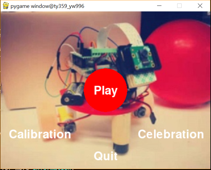
There are three modes in tracking robotic car. We use pygame library to implement visual interface to control them as the following picture shown.
Our objective is to make the balloon as center as possible. From the respective of the image input, the size of the image is 640*480 and thus the center of the image should be (320, 240). The image processing would recognize the red balloon, find out the contour, and calculate the center point and area.
Given the balloon’s coordinates and the area, which is the system output, we would be able to control the robot with a closed loop controller. To make a simple closed loop controller, we choose PID controller. The benefits are one that it is simple, and second it is robust enough for our robot.
PID algorithm is a closed loop control algorithm. PID stands for proportional-integral-derivative. It takes the present error, past error, and the future error as inputs to make appropriate control and thus reduce the error.
\(
u(t) = K_p e(t) + K_i \int_{t}^{0} e(\tau) d\tau + K_d \frac{de(t)}{dt}
\)
We can also write the algorithm with the following relationship.
\(
K_i = \frac{K_p}{T_i}, K_d = K_p T_d
\)
\(
u(t) = K(e(t) + \frac{1}{T_i} \int_{t}^{0} e(\tau) d\tau + T_d \frac{de(t)}{dt} )
\)
Actually, not all PID controller used up three terms. To be more specific, the there are controllers like
Ti is the period of the integration time, and Td is the period of the oscillation time.
For the reason that I-term is generally considered as dangerous when implementing PID controller, we only choose P controller and PD controller.
So how do we actually control our robot with PID controller? We have three degree of freedom, which is the tilt motor for the camera, the forward velocity for the robot, and the rotation of the robot. The robot has a constraint on side ways that it couldn’t move directly to the left or right. Thus, we overcome this problem by rotating the robot with motor rotating in the opposite direction. The forward and backward velocity is depending on the balloon area shown on the image. The rotation of the robot is depending on the X axis differential of from the image center. The camera tile motor is depending on the Y axis differential of from the image center.
To achieve our goal of tracking a falliing and moving balloon and pop it, we must decrease the latency and running time of every part as far as possible. At the beginning, the recognition and the course of sending order to control the motors and servo took about 105ms, which means it only processed less than ten pictures every second and it is far away from what we should do since we need to track the moving object and we only have limited time to decide the car’s movement. This delay time is too long. To reduce the delay time, one solution is to parallel process different task because of four cores in R-Pi, we can assign four jobs into four cores. In python, we could use the multiprocessing library to fully take advantage of four cores of R-Pi.
This describes the tasks that every core executes and the time they spend. The longest time is up to the frequency of the Pi camera, which is unchangeable to some degree. So this multiprocessing system has optimized the entire program and decrease the running time every loop from 105 ms to 34 ms. Note that the “print” syntax will cause the delay and if wanting show the image onto the monitors, it will increase delay time.
Starting from top left video, and go clockwisely in order.
The robot's rotation is depend on the X differential for the red balloon. We implemented a PD controller.
The robot's velocity is depend on the object's area. If the detected area is smaller than our reference area, the robot should go forward. And vice versa.
Here are the issues we have faced before, and our solution towarded the problems.
Since our robotic car need to track the falling balloon and move to the landing location very fast and considering that python is a kind of interpreted programming language and C++ is a complied programming language, we initially planned to install C++ version of openCV. We tried to install the C++ OpenCV library several times and every time it took more than three hours to compile it. We finally installed the C++ openCV successfully but when we tried to run some codes, it failed and said that it cannot open the Pi camera, which took us about one week. After discussion with Professor Skovira, we decide to use python openCV first and see whether it can meet our requirement. But we will still introduce how to install C++ openCV here briefly.
It should work, but there will definitely be a lot of errors. Good Luck!
After python OpenCV library installed, we tried to run testing code, there is one error saying “OpenCV Error: Assertion failed (scn == 3 || scn == 4) in cvtColor, file /build/opencv-U1UwfN/opencv-2.4.9.1+dfsq1/modules/imgproc/src/color.cpp, line 3737”. We searched it on Google, this error can be fixed by running “sudo modprobe bcm2835-v4l2“, which is used to intall the v412 driver on the bcm2835. We thought it is one time install but when the R-Pi reboot, the same error appeared again. Therefore, we add this command into /etc/modules. Then, it can work smoothly.Remember to add this command line in ~/.bashrc so that you don't have to enter every time you open up a new shell.
To control the servo of pan tilt kit, under the recommendation of Professor Skovira, we use the hardware PWM to generate control signal instead of software PWM, this is because the signal generated by hardware PWM is stable and less noise in a R-Pi multiprocessing environment. When we following the instruction from the professor to build the hardware PWM file and connect the circuit, we cannot send any signal to the GPIO pin. After asking other students who have experience to implement the hardware PWM, we know some very significant points. One is only GPIO pin 12 and pin 13 can be used to generated hardware PWM signal. Another is before running the code, we need to run “sudo pigpiod” to launch the pigpio library as a daemon.
Since we have to track a falling balloon, we need faster motors for our robot. Thankfully, with the help from Professor Skovira, we decide to abandon the previous continous rotation servo and replaced it with DC motors. Also, it is controlled via different voltage input from 3VDC to 6VDC. It worked in the sample test. However, when we combined it to the multiprocessing program, it cause the processors to oveload and stop it from working in a short time. Now, we are sure that both programs worked before adding them together. We, then, printed out how much does every single computing time a processor took. The result is the processor that contain DC controller is the murder in our code. It took 202 ms for a single compute cycle, which should only be 50 ms or less. It signed that DC controller had caused the latency, and filled up the shared contour queue. Now, it's obvious that in the DC library there are some latency. Just as we expected, the library consisted a time sleep for 200 ms, which accurately match the 202 ms as we measured. By cutting down the sleep time in the library, we successfully fix the latency caused by the DC controller.
Initially, we were very concerned about that torque and speed of our motor. Since tossing a ball and catch it before it lands is a hard job to achieve, the robot would require a high speed motor and high speed object detection. To achieve this goal, we were thinking about designing a new gear box with lower reduction ratio. By lowering the reduction ration, the motor would have higher speed but lower torque. It is possible that the new designed gear box wouldn’t work out and ended up consuming us a lot of time. Also, both of us had few knowledges about designing a 3d object, not to mention designing a gear box. As a result, we decided to stay with the original reduction ratio and take the easier task to design the motors’ bracket.
Overall, we approximately meet the goals outlined in the description. Still, there are several changes that allow us to finish the project in a short time. First, rather than installing two cameras for object distance detection, we represent the distance from the object area in an image. Second, rather than catching the balloon into a bucket, we use needles to pop the balloon which would dramatically show the catching result.
Our robot achieved the objective to terminate the balloon before it lands. Also, we realized that if it wasn’t balloon, the ball would only spend two seconds before it lands. On the other hand, if the ball is changed to a balloon, the air resistance would slow down the dropping balloon.
Nevertheless, if the robot is equipped with two cameras, it would take more computing time and would eventually slow down the tracking efficiency. Take our project as an example, our tracking function need 10 milliseconds to compute the object contour and 2 milliseconds to compute the control output. The new input image is renewed with every 30 milliseconds (30fps). If it were two cameras input the images, the contour calculating function would be doubled up. Thus, the output time from fetching an image and output a control signal could take more than 25 milliseconds in idea way. Moreover, we weren’t using higher priority from CPU, there would definitely be more latency when executing the program.
We would spend more time on developing the algorithm for estimating an object’s trajectory. Because there were times that the robot couldn’t track the balloon if it suddenly moved away, we would need a trajectory prediction algorithm to overcome this issue.
Also, during tracking mode the robot wasn’t performing its rotation obviously. We would refine the speed controller for faster response when it is moving forward and rotating.
| Item | Unit Cost | Quantity | Total Cost |
|---|---|---|---|
| Raspberry Pi Camera | $29.95 | 1 | $29.95 |
| DC Motors(From Prof. Skovira) | $2.95 | 2 | $5.9 |
| Tilt Kit and Servos | $8.89 | 1 | $8.89 |
| DC Motor Controller | $29.95 | 1 | $29.95 |
| Balloon | $2.94 | 1 | $2.94 |
| Safe Pin | $1.98 | 1 | $1.98 |
| 3D Printer | Free | n | Free |
| Total | $79.61 |
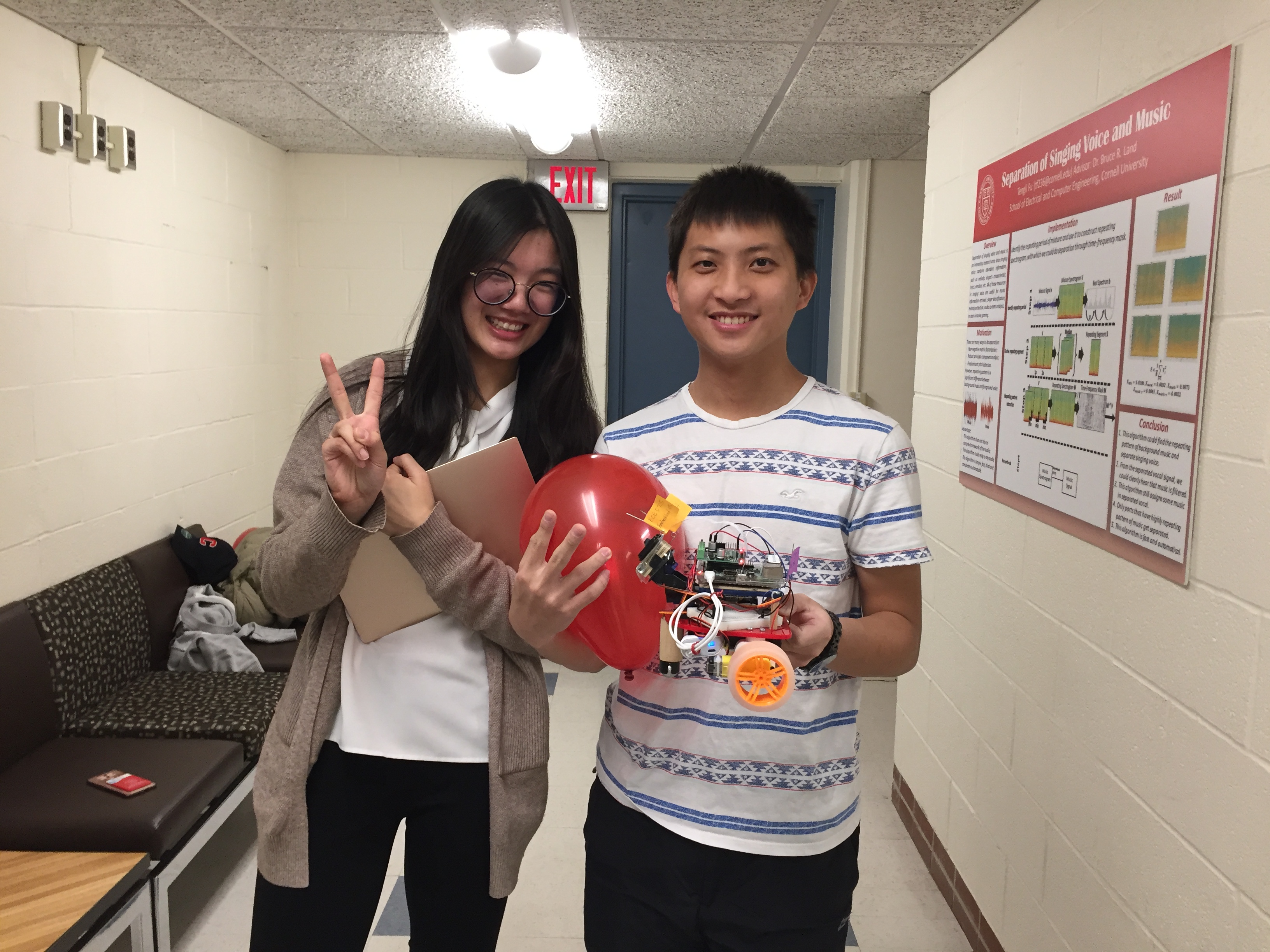
Figure: The Lucky Team - Yanling and David
Yanling Wu
Object Recognition Algo, Multiprocessing Algo, Hardware PWM, Pygame Interface, Website
Yeh Ta Wei
Self-Design Motor Bracket, DC Controller, PID Control Algo, Website
Thanks to Professor Joseph Skovira and TAs for giving us advice and help.
For more code examles, please visit our github XiaoPi_Luck.
1 2 3 4 5 6 7 8 9 10 11 12 13 14 15 16 17 18 19 20 21 22 23 24 25 26 27 28 29 30 31 32 33 34 35 36 37 38 39 40 41 42 43 44 45 46 47 48 49 50 51 52 53 54 55 56 57 58 59 60 61 62 63 64 65 66 67 68 69 70 71 72 73 74 75 76 77 78 79 80 81 82 83 84 85 86 87 88 89 90 91 92 93 94 95 96 97 98 99 100 101 102 103 104 105 106 107 108 109 110 111 112 113 114 115 116 117 118 119 120 121 122 123 124 125 126 127 128 129 130 131 132 133 134 135 136 137 138 139 140 141 142 143 144 145 146 147 148 149 150 151 152 153 154 155 156 157 158 159 160 161 162 163 164 165 166 167 168 169 170 171 172 173 174 175 176 177 178 179 180 181 182 183 184 185 186 187 188 189 190 191 192 193 194 195 196 197 198 199 200 201 202 203 204 205 206 207 208 209 210 211 212 213 214 215 216 217 218 219 220 221 222 223 224 225 226 227 228 229 230 231 232 233 234 235 236 237 238 239 240 241 242 243 244 245 246 247 248 249 250 251 252 253 254 255 256 257 258 259 260 261 262 263 264 265 266 267 268 269 270 271 272 273 274 275 276 277 278 279 280 281 282 283 284 285 286 287 288 289 290 291 292 293 294 295 296 297 298 299 300 301 302 303 304 305 306 307 308 309 310 311 312 313 314 315 316 317 318 319 320 321 322 323 324 325 326 327 328 329 330 331 332 333 334 335 336 337 338 339 340 341 342 343 344 345 346 347 348 349 350 351 352 353 354 355 356 357 358 359 360 361 362 363 364 365 366 367 368 369 370 371 372 373 374 375 376 377 378 379 380 381 382 383 384 385 386 387 388 389 390 391 392 393 394 395 396 397 398 399 400 401 402 403 404 405 406 407 408 409 410 411 412 413 414 415 416 417 418 419 420 421 422 423 424 425 426 427 428 429 430 | ######################################################### ### Yanling Wu (yw996), Yeh Dawei(ty359) ## ### This is the main code for tracking the red balloon ## ### and try to pop the balloon ## ######################################################### from multiprocessing import Process, Queue, Value, Lock, Array import time import numpy as np import cv2 from datetime import datetime from motor_controller import motor_controller import RPi.GPIO as GPIO import sys import subprocess import pigpio from motor_controller import motor_controller #set fro broadcom numbering not board numbers GPIO.setmode(GPIO.BCM) # Set Up Pan Tilt Servo HardwarePWM Pins motorPinT = 12 # connect to pi gpio Daemon pi_hw = pigpio.pi() #set the original position of tilt of camera currentDutyCycleT = 115000 # look at forward #Rotate the camera to make the balloon in the center of the image def rotate_camera(dir, strength): global currentDutyCycleT full_up = 65000 # 1.3ms -> up full_down = 115000 # 2.3ms -> forward #increment is 200 everytime increment = (full_down - full_up) / 200 #camera up if dir == 1: currentDutyCycleT = currentDutyCycleT - strength * increment if currentDutyCycleT < full_up: currentDutyCycleT = full_up elif dir == 0: pi_hw.hardware_PWM(motorPinR, 50, 0) #50 Hz Freq. 0% duty cycle pi_hw.hardware_PWM(motorPinT, 50, 0) #50 Hz Freq. 0% duty cycle currentDutyCycleT = currentDutyCycleT - strength * increment if currentDutyCycleT < full_up: currentDutyCycleT = full_down #camera down else: currentDutyCycleT = currentDutyCycleT + strength * increment *2 if currentDutyCycleT > full_down: currentDutyCycleT = full_down pi_hw.hardware_PWM(motorPinT, 50, currentDutyCycleT) #50 Hz Freq. ##print("rotate_camera Function : change the camera\n") tilt_time = time.time() # record the length of giving order to tilt #Master Process --- recognize the red balloon def recognize_balloon(send_frame_queue, p_start_turn, p_end_turn, p_start_lock, p_end_lock): last_contour_receive_time = 0 start_queue = datetime.now() count_put = 0 global count1 global count2 global count3 global run_flag time_total_run = time.time() waiting_threshold = 10 calibration = False #print(run_flag.value) while(run_flag.value): try: run_time = time.time() #1. get a frame and show ret, _, frame = cap.read() # height 480; width 640; channel 3 #cv2.imshow('Capture', frame) #2. change to hsv model hsv = cv2.cvtColor(frame, cv2.COLOR_BGR2HSV) #3. Threshold the HSV image to get only red colors and get mask mask = cv2.inRange(hsv, lower_red, upper_red) #lower than # #print(mask) # cv2.imshow('Mask_first', mask) #print('count1 %d, count2 %d, count3 %d'%(count1, count2, count3)) cur_time = datetime.now() delta_time = cur_time - start_queue delta_time_tol_ms = delta_time.total_seconds()*1000 if (calibration): #print("Calibration the camera") pass else: #only put the mask in queue if it has past 10ms and there are less than 4 masks in queue if (delta_time_tol_ms > waiting_threshold) and (send_frame_queue.qsize() < 2) : start_queue = cur_time # Update last send to queue time send_frame_queue.put(mask) # put mask in queue # print("send_frame_queue", send_frame_queue.qsize()) count_put += 1 #print("put the mask to queue\n") # draw the contour of the balloon in the opencv interface but we comment it when runing to decrease the latency #if ((time.time()-last_contour_receive_time) < waiting_threshold/1000.): #cv2.circle(frame, (cx, cy), 7, (255, 255, 255), -1) #Draw center of object #cv2.drawContours(frame,contours,-1,(255,0,0),3) #Draw contour of object #cv2.circle(frame, (center_x, center_y), 2, (0, 0, 255), -1) #Draw center of camera #cv2.imshow('frame',frame) #Display Frame # print("processor 0 time\n\n\n\n ", time.time() - run_time) if cv2.waitKey(1) & 0xFF == ord('q'): run_flag.value = 0 time_total_run = time.time() - time_total_run print('count_put %d' % count_put) #print('count_#print_x %d' % count_#print_x) print('Total running time' , time_total_run) print("Time to process", time_total_run/count_put) except KeyboardInterrupt: run_flag.value = 0 time_total_run = time.time() - time_total_run print('count_put %d' % count_put) #print('count_#print_x %d' % count_#print_x) print('Total running time' , time_total_run) print("Time to process", time_total_run/count_put) #print("Quit Processor 0") def process_contour_1(send_frame_queue, receive_contour_queue, p_start_turn, p_end_turn, p_start_lock, p_end_lock): global count1 global run_flag while (run_flag.value): try: run_time = time.time() # startTime = datetime.now() # startTime_ms = startTime.second *1000 + startTime.microsecond/1000 # If frame queue not empty and it is Worker Process 1's turn if ((not send_frame_queue.empty()) and (p_start_turn.value == 1)): # print("1 send_frame_queue ", send_frame_queue.qsize()) mask = send_frame_queue.get() # Grab a frame #count1 = 1 + count1 #print("count1 %d" % count1) p_start_turn.value = 1 # and change it to worker process 2's turn #print("Processor 1's Turn - Receive Mask Successfully") ##print(mask.shape) # 1. Implement the open and close operation to get rid of noise and solidify an object # maskOpen=cv2.morphologyEx(mask,cv2.MORPH_OPEN,kernelOpen) # maskClose=cv2.morphologyEx(maskOpen,cv2.MORPH_CLOSE,kernelClose) # # 2. Extract contour # contours,h=cv2.findContours(maskClose.copy(),cv2.RETR_EXTERNAL,cv2.CHAIN_APPROX_NONE) #find contours contours,h=cv2.findContours(mask,cv2.RETR_EXTERNAL,cv2.CHAIN_APPROX_NONE) receive_contour_queue.put(contours) # Put contour back #print("processor_1 : put contour successfully\n") # print("1 receive_contour_queue ", receive_contour_queue.qsize()) else: ##print("Processor 1 Didn't Receive Frame, sleep for 10ms") time.sleep(0.01) currentTime = datetime.now() currentTime_ms = currentTime.second *1000 + currentTime.microsecond/1000 # print("processor 1 time \n\n\n\n ", time.time() - run_time) ##print ("Processor 1 Processing Time: " + str(currentTime_ms-startTime_ms)) except KeyboardInterrupt: run_flag.value = 0 #print("Quiting Processor 1") # Function for the Worker Process 2 def calculate_contour_2(receive_contour_queue, send_motor_queue, p_start_lock, p_end_lock): global count2 global tilt_time global currentDutyCycleT global run_flag # global p0,p1,p2,p3 x_diff = 0 y_diff = 0 area_diff = 0 last_areaDiff = 0 area = 0 last_xdiff = 0 last_ydiff = 0 start_time = 0 waiting_threshold = 20 count_no_contour = 0 #print("I am here1") tilt_lst = [0,0] count = 0 Period = 200 controller = motor_controller() while (run_flag.value): try: if ((not receive_contour_queue.empty())): #last_contour_receive_time = time.time() contours = receive_contour_queue.get() # Extract contour # print("Main Processor 2: Get the processed contour from queue\n") # print("2 receive_contour_queue ", receive_contour_queue.qsize()) count2 +=1 #print("count2 ", count2) Area_list = [] if 0 == len(contours): # print("Calibration --- finding balloon\n\n\n\n\n") # controller.set_control( 0, 0) controller.set_control( 0, 10) if count < Period/2: tilt_lst[0] = 1 tilt_lst[1] = 1.0 if count >= Period/2 and count < Period: tilt_lst[0] = -1 tilt_lst[1] = 1.0 if count == Period: count = 0 count += 1 time.sleep(0.01) # print currentDutyCycleT if (send_motor_queue.qsize() < 2) : send_motor_queue.put(tilt_lst) if count_no_contour > 150: run_flag.value = 0 controller.clean() if run_flag.value == 0: p0.terminate() p1.terminate() p2.terminate() p3.terminate() # yeh_David time.sleep(waiting_threshold/1000.) count_no_contour += 1 else: count_no_contour = 0 run_time = time.time() Area_list = [ cv2.contourArea(c) for c in contours ] ##print (Area_list) maxindex = Area_list.index(max(Area_list)) ##print maxindex cnt = contours[maxindex]#Get the first contour ##print (contours[0]) M = cv2.moments(cnt)#Calculat M of the first contour # #print (M) #calcualte the center coordinate if M['m00'] != 0: cx = int(M['m10']/M['m00']) cy = int(M['m01']/M['m00']) area = M['m00'] #PID control Algo to calculate strength to control servo x_diff = cx - center_x y_diff = abs(cy - center_y) area_diff = area_ref - area # #print("x_bar=%f, y_bar= %f" % (cx,cy)) # #print("x_diff= %f, y_diff= %f" % (x_diff,y_diff)) # #print("area = %f" % area) #### PID Parameters #### kp_x = 1.0 kd_x = 0.001 ### ZH PID # Ku = 3 # kp_x = Ku*0.6 # Tu = 3 # Td = Tu/8 # kd_x = kp_x*Td kp_z = 6 kd_z = 0 kp_y = 6 kd_y = 0.001 proportional_x = x_diff proportional_y = y_diff/(y_res/2.0) proportional_z = area_diff derivative_x = (last_xdiff - x_diff)/(time.time() - start_time) derivative_y = (last_ydiff - y_diff)/(time.time() - start_time) derivative_z = (last_areaDiff - area_diff)/(time.time() - start_time) start_time = time.time() ##print("derivative_x: " + str(derivative_x)) ##print("derivative_x*kd_x: " + str(derivative_x*kd_x)) #start_time = time.time() strength_x = proportional_x*kp_x + derivative_x*kd_x strength_z = proportional_z*kp_z + derivative_z*kd_z strength_y = proportional_y*kp_y - derivative_y*kd_y ##print "strength:" ##print strength_x #Assume the left and top corner is (0,0) if ((abs(area_diff) <= area_tlr or currentDutyCycleT == 65000) and abs(x_diff) <= x_tlr ): c = 1 controller.set_control( 0, 0) else: controller.set_control( strength_z*0.005, strength_x*0.05) #strength_z*0.005, strength_x*0.05 # print("area didn't meet the reference") if (y_diff <= y_tlr): # do nothing within tolerance range b = 1 elif (cy > center_y): tilt_lst[0] = 1 tilt_lst[1] = strength_y ##print('the camera need to raise its head up\n') else: tilt_lst[0] = -1 tilt_lst[1] = strength_y ##print('the camera need to low its head down\n') length_time = time.time() - tilt_time tilt_time = time.time() last_area = area last_xdiff = x_diff last_ydiff = y_diff last_areaDiff = area_diff # #print(tilt_lst) # print(send_motor_queue.qsize()) #print(tilt_lst) if (send_motor_queue.qsize() < 2) : send_motor_queue.put(tilt_lst) # put mask in queue #print("send_motor_queue", send_motor_queue.qsize()) #print("tilt time", length_time) # print("processor 2 time ", time.time() - run_time)#print the running time of processor 2 else: #print("Processor 2 Didn't Receive Frame, sleep for 10ms") time.sleep(0.01) except KeyboardInterrupt: run_flag.value = 0 controller.clean() pi_hw.stop() ##print ("Processor 2 Processing Time: " + str(currentTime_ms-startTime_ms)) #print("Quiting Processor 2") # Function for the Worker Process 3 def process_motor_3(send_motor_queue, p_start_lock, p_end_lock): global count3 global run_flag #print("you are there!") while (run_flag.value): run_time = time.time() try: if (not send_motor_queue.empty()): tilt_lst = send_motor_queue.get() #print("get motor queue successfully") count3 += 1 #print("count3 %d" % count3) for i in range(1,2): rotate_camera(tilt_lst[0],tilt_lst[1]/i) if (not send_motor_queue.empty()): break time.sleep(10/1000.) else: #print("Processor 3 didnt receive the tilt list\n") time.sleep(0.01) ##print ("Processor 3 Processing Time: " + str(currentTime_ms-startTime_ms)) # print("processor 3 send command") # print("processor 3 time\n\n\n\n ", time.time() - run_time) except KeyboardInterrupt: run_flag.value = 0 #print("Quiting Processor 3") # set red thresh lower_red = np.array([156,100,40]) #156, 100, 40 upper_red = np.array([180,255,255]) x_res = 640 #320 y_res = 480 #240 resolution = x_res*y_res center_x = x_res/2 center_y = y_res/2 area_ref = resolution*4/5 tolerance = 5 / 100. x_tlr = x_res * tolerance y_tlr = y_res * tolerance area_tlr = resolution * tolerance # Setting Kernel Convolution Parameters kernelOpen=np.ones((5,5)) kernelClose=np.ones((20,20)) cap = cv2.VideoCapture(0) # cap.set(3, x_res) # cap.set(4, y_res) count1 = 0 count2 = 0 count3 = 0 if __name__ == '__main__': # run_flag is used to safely exit all processes run_flag = Value('i',1) # p_start_turn is used to keep worker processes process in order p_start_turn = Value('i', 1) p_end_turn = Value('i', 1) send_frame_queue = Queue()#send frame to queue receive_contour_queue = Queue()# send the processed contour to the queue send_motor_queue = Queue() p_start_lock = Lock() #Safety lock, but didnt use p_end_lock = Lock() #Safety lock, but didnt use p0 = Process(target=recognize_balloon, args=(send_frame_queue, p_start_turn, p_end_turn, p_start_lock, p_end_lock)) p1 = Process(target=process_contour_1, args=(send_frame_queue, receive_contour_queue, p_start_turn, p_end_turn, p_start_lock, p_end_lock)) p2 = Process(target=calculate_contour_2, args=(receive_contour_queue, send_motor_queue, p_start_lock, p_end_lock)) p3 = Process(target=process_motor_3, args=(send_motor_queue, p_start_lock, p_end_lock)) p0.start() p1.start() p2.start() p3.start() # Wait for four processes to safely exit p0.join() p1.join() p2.join() p3.join() #Turn off cv2 window pi_hw.hardware_PWM(motorPinT, 0, 0) # 0hz, 0% duty cycle -- stop the motor! pi_hw.stop() # close pi gpio DMA resources cap.release() cv2.destroyAllWindows() |