
IMU Calibration
Due to fabrication inaccuracy, the 3 axes of the accelerometers and the 3 axes gyroscopes are usually misaligned, causing an error between the Euler Angle of two coordinates. Calibration is needed. Using the 6-pos calibration technique, we setup the 6 calibration position as follows:
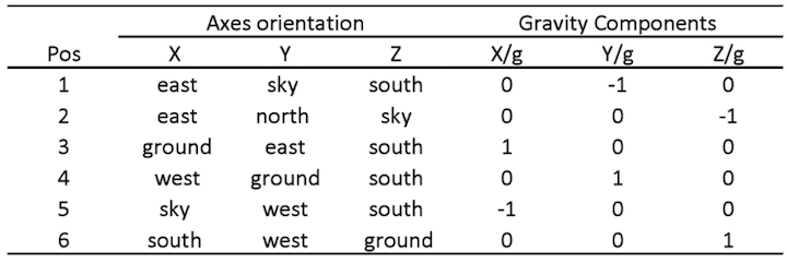
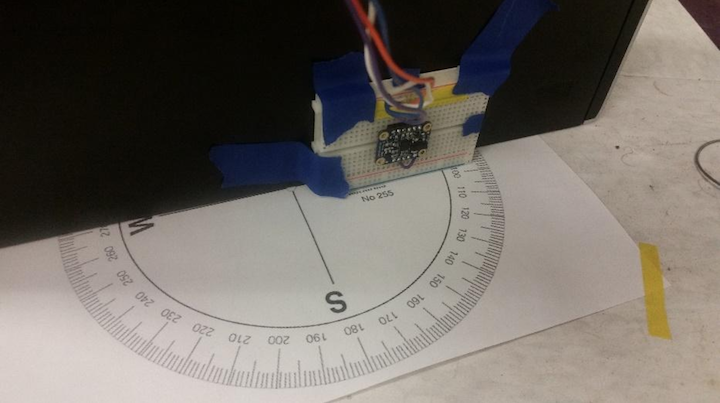
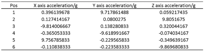
Using a self-made calibration table (Figure XX) we fix the imu to the 6 positions and record the reading, the calibration data gathered by these six positions are:
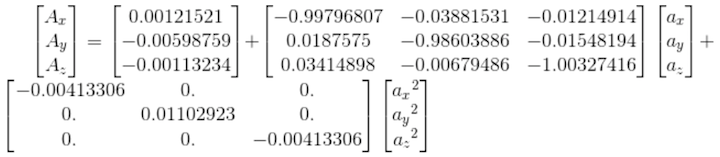
The acceleration data after calibration is (Ax, Ay, Az are data after calibration and ax, ay, az are raw data):
Sensor Fusion For Raw Data
Quaternion calculation:
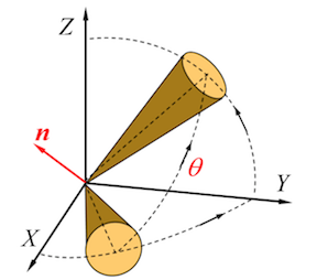
Quaternion is a representation of the orientation and rotation of the object, and it is easier to compute the rotation of vector than the Euler Angles. The transaction between the quaternion and the Euler Angle is shown below:
$$ \textbf{q} = { \cos {\theta \over 2} + \sin{\theta \over 2} \cos {\alpha} \cdot \textbf{i} + \sin {\theta \over 2}\cos {\beta \over 2} \cdot \textbf{j} + \sin {\theta \over 2} \cos {\gamma} \cdot \textbf{k}} $$
$$ \textbf{q} = { \lambda + P_{1} \textbf{i} + P_{2} \textbf{j} + P_{3} \textbf{k}} $$
Quaternion rotation:
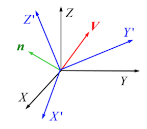
For a fixed vector V coordinated in frame XYZ, it could be represented in quaternion:
$$ V= 0 + V_xi + V_yj+V_zk $$
If the frame rotates for q, become X’Y’Z’, V coordinated in X’Y’Z’ could be represented as:
$$ V^{’}= 0 + V_{x}^{’}i^{’} + V_{y}^{’}j^{’}+V_{z}^{’}k^{’} $$
Then, $$ V = q \circ V^{’} \circ q^{-1} $$
However, using the raw data generated by the gyroscope is still not enough, because of the misalignment mentioned in calibration part, the gravity vector obtained by the accelerometer need to be considered. The function ‘UpdateIMU’ is used to calculate the error between the gravity vector calculated by gyroscope and the gravity vector measured by the accelerometer. This function was run 2000 times at the beginning stationary stage with no movements nor rotations, and using a feedback to calculate the error. The function is shown below:
1 2 3 4 5 6 7 8 9 | def UpdateIMU(self, Gyr, Acc): if np.linalg.norm(Acc) == 0: warnings.warn("Accelerometer magnitude is zero. Algorithm update aborted.") return else: Acc = np.array(Acc / np.linalg.norm(Acc)) v = np.array([[2*(self.q[1]*self.q[3] - self.q[0]*self.q[2])], [2*(self.q[0]*self.q[1] + self.q[2]*self.q[3])], [self.q[0]**2 - self.q[1]**2 - self.q[2]**2 + self.q[3]**2]]) |
Variable “Acc” and ‘v’ are both normalized gravity vector calculated by the accelerometer and the gyroscope, then the angular deviation (error) between the two vector could be represented using their cross product:
1 | error = np.cross(v,np.transpose([Acc]),axis = 0) |
The calculated error could also be integrated to update the gyroscope reading using PI negative feedback loop (that’s why we need to run this function 2000 times, so the PI loop could converge):
1 2 | self.IntError = self.IntError + error Ref = Gyr - np.transpose(self.Kp*error+self.Ki*self.IntError) |
The quaternion could then be calculated by the corrected gyroscope data:
1 2 3 4 | pDot = np.multiply(0.5 , self.quaternProd_single(self.q, [0, Ref[0,0], Ref[0,1], Ref[0,2]])) self.q = self.q + pDot * self.SamplePeriod; self.q = self.q / np.linalg.norm(self.q); self.Quaternion = self.quaternConj(self.q); |