Overall Setup
Inertial measurement unit (IMU) on the module is used to gather the acceleration and rotation information of the moving object. Two different devices were used: LSM9DS0 and BNO055 the hardware connection is shown below (I2C is used for the connection for LSM9DS0 and UART is used for the connection for BNO055).
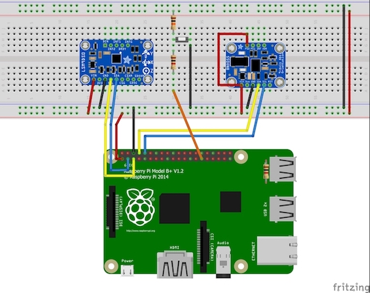
LSM9DS0 is a 9 DOF IMU with could provide the raw accelerometer, gyroscope and magnetometer data with the scale set to +_ 2g for acceleration, +- 245 dps for angular rate and gyroscope disabled. And BNO055 is an absolute orientation sensor with an onboard microcontroller doing the sensor fusion for the IMU raw data output, and could generate the acceleration data without the gravity component as well as the quaternion of the IMU with respect to the world frame.
IMU Movement Restore
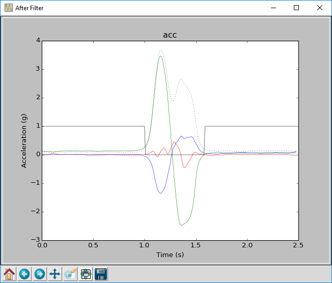
To restore the movement data, we need to do the integration for the acceleration data. However, as can be seen in the figure, there are a significant amount of noises on the raw data and needed to be removed.
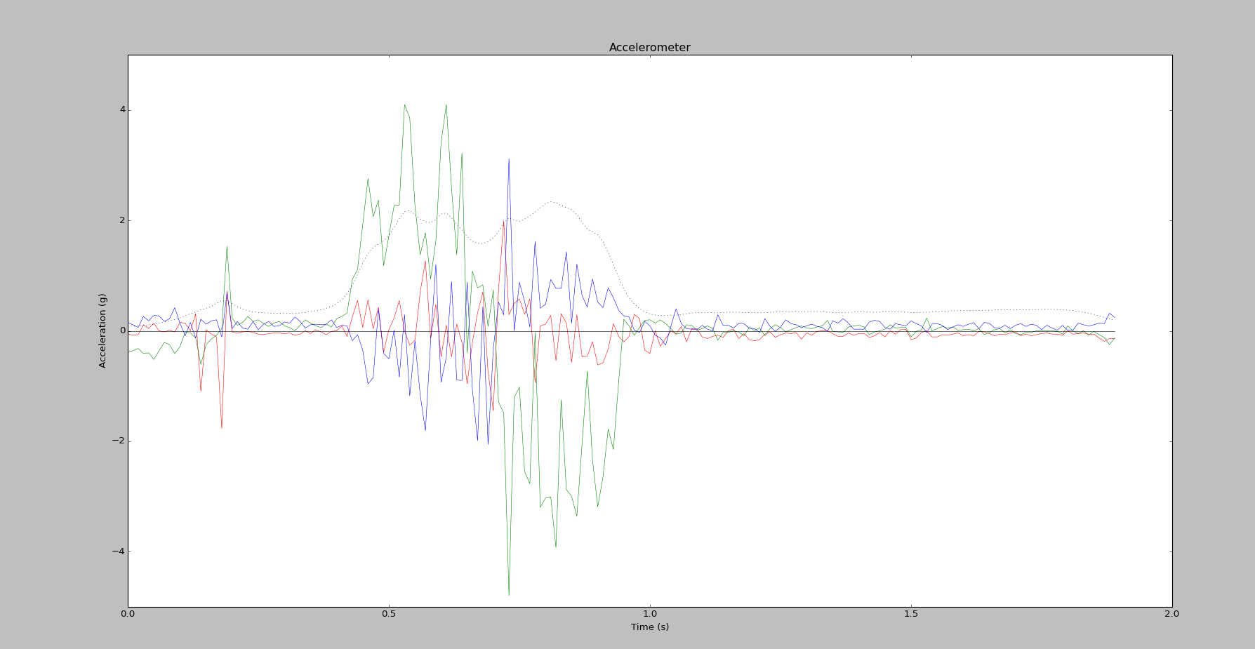
A low-pass butterworth filter and a high pass butterworth filter is applied to the acceleration data, the low-pass filter is to remove the spikes, and the high pass filter is used to remove the noises. The filters and acceleration data after the filter are shown below:
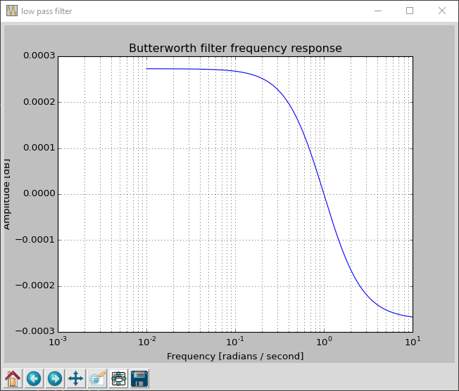
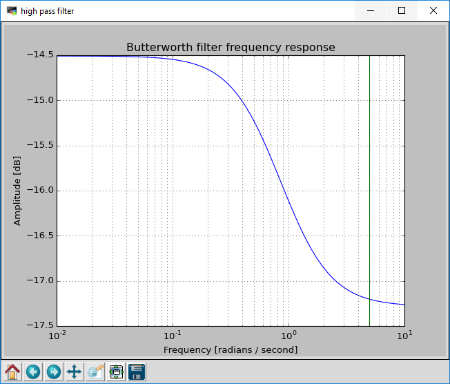
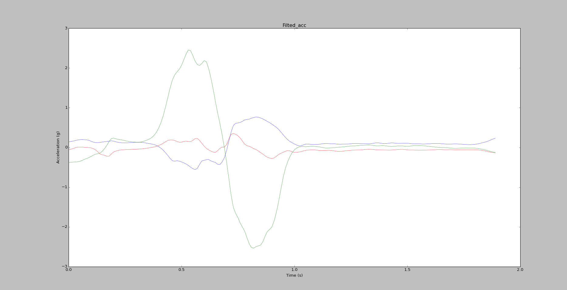
It could be seen that the noises and spikes are greatly removed.The magnitude of the acceleration is also filtered by the filters and the parts where the magnitude is smaller than a threshold 0.05 is called stationary parts, and to minimize the drift in the stationary parts, we only do the integration of the acceleration in the nonstationary parts.
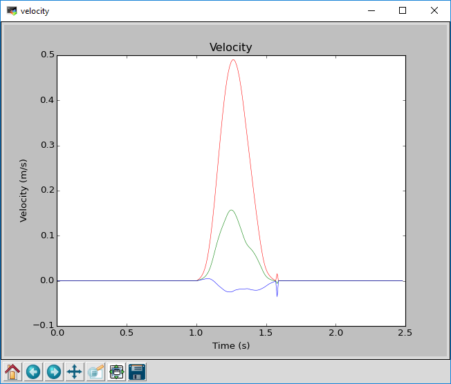
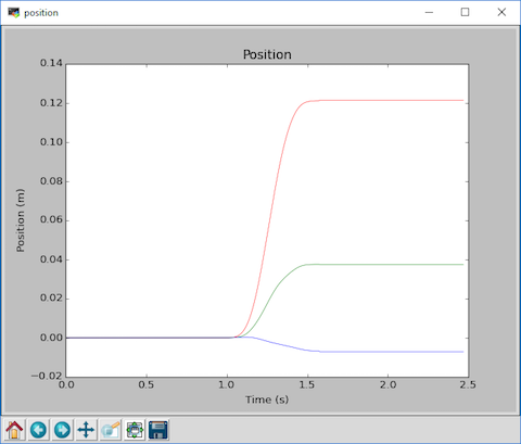
The acceleration data is represented in the IMU frame with a quaternion of q with respect to the world frame. Using the quaternion rotation of the frame mentioned in the “background knowledge” part, we could transfer the acceleration vector in IMU frame to the world frame. The velocity and position information calculated by the integration of the acceleration data could be seen below:
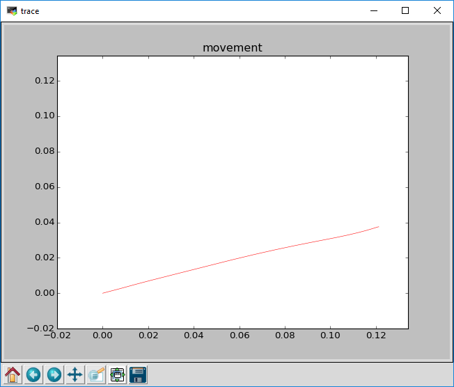
The movement in the world X-Y plane could be seen as:
More experiment result could be seen below:
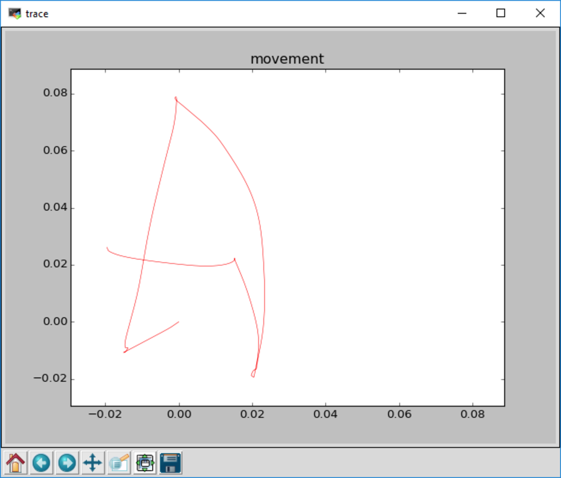
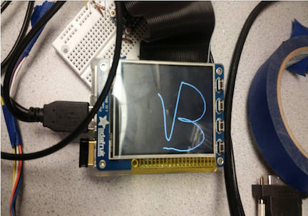
Pygame Setup
To make the IMU movement easier to see between each update, we used Pygame to draw the trace of the IMU. We use a press button connected to the Pi GPIO input port to control the trace update, after the first press of the button, the system will begin to record the movement, and will stop the record at the second press. Then the movement recorded by the system will be scaled to fit the size of the TFT screen, and draw on the screen. The result could be seen as below: