Pi-TFT Interfacing
Code for this section was developed by Mayank Sen Sharma and Siddharth Mody
Design
PiTFT Integration:
The first step was to integrate the PiTFT with the R-Pi module. It involved downloading and installing the PiTFT kernel. The steps mentioned on the website www.learn.adafruit.com were taken as a reference to complete the installation. The /boot/config.txt file was edited to add the device tree overlay manually. The orientation of display was set to landscape mode by setting the ‘rotate’ variable to 90 degree. The screen refresh rate was set at 32MHz.
The next step was to add support for touchscreen automatically on bootup. The /etc/modules file was edited to add ‘stmpe-ts’ line and system was rebooted. A calibration configuration directory (/etc/X11/xorg.conf.d) was created and the 99-calibration.conf calibration configuration file was added to it. Next, the AutoMagic calibration script was downloaded [1] and executed. These steps ensured that the piTFT was fully functional screen which could be used to give input for digit-recognition.
Reading and Displaying Input:
Initially, C++ was chosen as the preferred programing language to leverage the OpenMP compiler extension in later phases of project for program speed-up. A thorough investigation was done on how communication could be established between the C++ code and the piTFT screen. The problem was two-fold: get the user input using piTFT and also display the user drawing on the screen. It was noted that various online forums had pointed out to the fact that C++ interfacing with piTFT used to get too much complex since not many native libraries were available to support this interfacing. Hence, to develop an elegant and easy to use user-interface, it was decided to use python as the preferred programming language for piTFT interfacing
Python has a set of cross platform modules called “Pygame” designed for writing video games. It includes computer graphics and sound libraries designed to be used with the Python programming language. The Pygame module provided the useful resources that could be used to develop a user interface. Extensive literature survey was done and python code from NerdParadise[2] was taken as reference for developing initial program.
The first task was to collect the set of points where the stylus or the mouse pointer glided on the screen. This set of points were required in order to recognize the digit which resembled the figure drawn by the user. In order to accomplish this task, an array “points” was initialized which was appended with the co-ordinates over which the pointer glided on the screen. The program started recording the points from the moment the left mouse button was pressed or the stylus touched the piTFT screen till the moment the left mouse button was released or the stylus was lifted up. Each motion on the screen was detected as a new “event” by the Pygame module and the subsequent x,y co-ordinate was captured in the array. As the stylus or the mouse pointer moved on screen, the array kept getting appended with new values of coordinate. Once the user completed drawing the figure, the python code detected the “event” wherein the user lifted the stylus or the mouse button. This event was used to stop recording the points and quit the pygame module. At the start of the code when Pygame was initialized, the screen size was set at 320 X 240 pixels. This resembled the 2.8 inch piTFT screen which was being used for this project.
The second task for this phase of the project was to display the figure drawn by the user in realtime. This was a necessary addition in order to make the code more user friendly and enable the user to see what input has been given by him/her. To accomplish this task, the array consisting of x,y coordinate of all the pixels visited by stylus was used to draw the figure on screen. After every motion of stylus, the updated array was passed to a function which drew lines between all the points present in the array. Thus the user could observe in real-time the input given by him/her.

After the user completed drawing the figure on the screen, the array of coordinates is passed to the main function as raw data. This raw data needs to be processed in order to identify the digit drawn on the screen. Since the length of the array containing the coordinates vary each time a new figure was drawn, the raw data can’t be directly used for digit recognition. Hence, the set of coordinates is converted into a standard data format of fixed data-width. In addition, for fast computation and save memory, the resolution of data was reduced from 320 x 240 to 20 x 15. This transformation ensured reduction in size of data-set and at the same time enough differentiation could be made between different digits. If any part of the 20x15 screen was visited by stylus, it was marked as one, otherwise 0. The array containing set of two dimensional x-y coordinates was converted into a one dimensional array of 300 points. This was achieved by dividing each coordinate by a factor of 16 and unfolding the two dimensional x-y matrix. The resulting array contained set of 300 points which were either one or 0. Now the data was ready to be processed and passed to digit-recognition algorithm.
Gesture Recognition using X-stroke on Raspberry Pi [3]
After extensive research on gesture recognition, a tool called X-stroke was installed on Raspberry-Pi to enable touchscreen interface for character recognition. This tool has a pre-defined set of symbols defined as training data. Whenever any test character is drawn on the pi-TFT screen using inbuilt pencil, it recognizes the input character with high accuracy. As this tool was readily built and tested on our Raspberry-Pi, we planned to move ahead with developing a program code for digit recognition using Raspberry-Pi. The figure below shows the character recognition implemented using x-stroke on Raspberry-Pi.
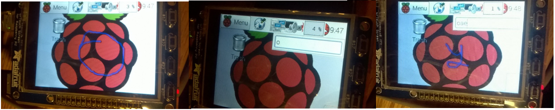
Figure 2: X-stroke output
Testing
The code was thoroughly tested for different inputs given by the user. It was ensured that all digits could be drawn easily on the screen. A sample bitstream generated by the code is shown in Figure 3.

Code
PiTFT Integration
# Code developed by Mayank Sen Sharma and Siddharth Mody
# for ECE5990 Project at Cornell University
#########################################################
# This codes takes input from user and converts it to
# a bit stream

import pygame
import operator
import os

os.putenv('SDL_FBDEV', '/dev/fb1')
os.putenv('SDL_MOUSEDRV', 'TSLIB')
os.putenv('SDL_MOUSEDEV', '/dev/input/touchscreen')

def get_points():
    pygame.init()
    screen = pygame.display.set_mode((320, 240))
    clock = pygame.time.Clock()

    radius = 5
    x = 0
    y = 0
    points = []

    while True:

        pressed = pygame.key.get_pressed()


        for event in pygame.event.get():

            if event.type == pygame.QUIT:
                return

            if event.type == pygame.MOUSEMOTION:
              if event.buttons[0]:
                # if mouse moved, add point to list
                position = event.pos
                points = points + [position]
                points = points[-500:]

            if event.type == pygame.MOUSEBUTTONUP:
	        pygame.quit()
                return points

        screen.fill((0, 0, 0))

        # draw all points
        i = 0
        while i < len(points) - 1:
            drawLineBetween(screen, i, points[i], points[i + 1], radius)
            i += 1

        pygame.display.flip()

        clock.tick(24)

# Function to draw the figure on screen
def drawLineBetween(screen, index, start, end, width):
    color = (255, 255, 255)

    dx = start[0] - end[0]
    dy = start[1] - end[1]
    iterations = max(abs(dx), abs(dy))

    for i in xrange(iterations):
        progress = 1.0 * i / iterations
        aprogress = 1 - progress
        x = aprogress * start[0] + progress * end[0]
        y = aprogress * start[1] + progress * end[1]
        pygame.draw.circle(screen, color, (int(x), int(y)), width)


# Main part of program

points = get_points()
# screen size 320 x 240
# dividing by a factor of 16
Matrix = [0 for x in range(20*15)]

i = 0
while i < len(points) - 1:
  x = int(points[i][0]/16)
  y = int(points[i][1]/16)
  i += 1
  Matrix [ x + 20*y ] = 1


print Matrix
Reference
[1] https://raw.githubusercontent.com/adafruit/PiTFT_Extras/master/pitft_touch_cal.py
[2] http://www.nerdparadise.com/tech/python/pygame/basics/part6/
[3] Mark Williams (2014, June 17). Ozzmaker.com/Raspberry-Pi Projecs [Online]. Available: http://ozzmaker.com/2014/06/17/raspberry-pi-with-stroke-and-gesture-recognition/
Contact
Mayank Sen Sharma (ms3272[at]cornell.edu), Siddharth Mody (sbm99[at]cornell.edu)
Graduate students of Class 2016 at Cornell University
Ack
Special thanks to Prof. Joseph Skovira and Gautham Ponnu