Objective top
Our final project, the Embedded Phone, is to construct a basic phone with calling capabilities using the Raspberry Pi, a touchscreen, and a GSM module. The Embedded Phone will also be able to receive calls and translate messages from the GSM module to the touchscreen. As the main control unit, the Raspberry Pi will utilize PyGame and RPi.GPIO Python libraries to improve the user interface and front-end of the project.
Introduction top
Today, almost everybody carries around a smartphone, which is basically a high-tech portable computer that is capable of performing more than just calling and texting. For example, the newest IPhone models from Apple allows you to make calls while browsing the internet, playing smartphone games, or checking emails. However, the first prototypes of the IPhone probably only had basic calling functionality before additional features were included. For our project, we will be improving upon the design of the PiPhone by David Hunt [1]. Hunt utilized the FONA GSM module, Raspberry Pi, and a thin-film-transistor (TFT) touchscreen for basic phone functionality. With the PyGame and RPi.GPIO library, he created a simple phone that only performs outgoing calls.
For this project, we designed and implemented an extension to the PiPhone to improve the usability of the phone. New features such as incoming calls and automatic "hang up" were included by referencing the command manual for the FONA GSM module. In addition, to the normal phone features, we also wanted to execute the code onto the real-time patch for the Raspbian kernel. The scheduling performed by the RT-patched Linux can potentially improve the overall speed of the Embedded Phone. However, we were unable to execute the Python script with full functionality and usability.
Design and Testing top
List of Components
| Raspberry Pi 2 Model B |
| 2.8 Inch PiTFT |
| 5V, 2A power adapter (mini USB) |
| Breadboard |
| 40 pin breakout cable |
| Ethernet Cable |
| FONA GSM Module |
| Mini GSM Quad-Band Antenna |
| GSM SIM Card |
| Headphones with Microphone |
For our project, we use two new components which we haven’t used in the lab. They are FONA GSM Module and the Mini GSM Quad-Band Antenna. This sub-section gives an overview of the functionality of the components before we get into details of the design.
FONA GSM Module
Figure 1: Top view of Adafruit FONA - Mini Cellular GSM Breakout - SMA Version - v1[2].
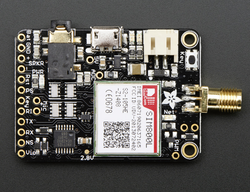
The component shown in figure 1 is the GSM module which we use in our project. It measures 1.75”x1.25”. Several important features of this module are:
- Quad-band 850/900/1800/1900MHz - connect onto any global GSM network
- Make and receive voice calls using a headset
- Send and receive SMS messages
- AT command interface with auto baud detection
- Standard 4-pole TRRS headphone jack
- SMA connection for external antenna
- Indicator LEDs for power and network connectivity
Connectors
Headset jack: A 3.5mm phone headset jack with stereo earphone and mono microphone. Vendors suggest not to use the official iPhone headset mic as it did not seem to work. Any other iPhone or Android compatible headset will work.
Antenna port: As the module provides an SMA connector, an SMA antenna can be directly connected.
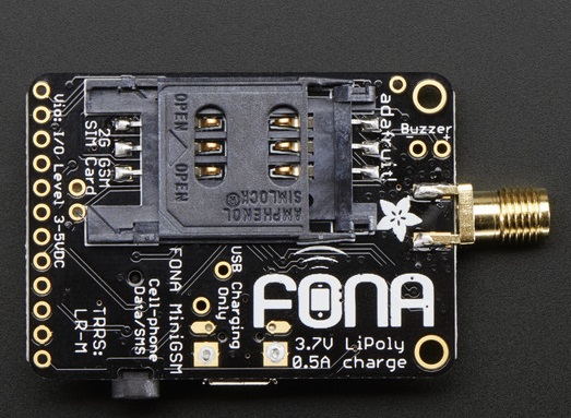
SIM Connector: A GSM Mini SIM card is required to use the module. Mini SIMs are 1" x 0.6". A SIM adapter can be used if you have a SIM of any other size. Figure 2 shows the bottom view of the module where the SIM can be inputted.
Figure 2: Bottom view of Adafruit FONA - Mini Cellular GSM Breakout - SMA Version - v1[2].
Breakouts
Few important pins are connected to header pins at the bottom of the board. The important pins which are used in our project are described below.
- Vio - This pin must be supplied with an external voltage of 3V-4.2V to set the logic level converter. The converter also buffers the indicators LEDs. So, this pin has to be powered for the module to be working.
-
Key - This pin is power on/off indicator. It is also connected to the button in the top left. To turn
the module on or off, this pin can be tied to ground for 2 seconds. This pin has to permanently
connected to ground if we never want to turn off the module for power saving.
-
PS- The Power Status pin is connected to PWR LED too. It indicates whether the module
is on or off.
-
NS - This is Network Status pin. It pulses to signal the current status of the module.
This is connected to the Net LED.
-
RX & TX - The module uses UART to send and receive commands and data. These pins are
auto-baud so whatever baud rate you send "AT" after reset or boot is the baud rate that is used.
RX pin is for receiving data and commands into the module, TX is transmitting data and
responses out of the module.
- RI - This pin is the Ring Indicator. It is an interrupt out pin from the module. It is set high by default and will pulse low for 120ms when a call is received. This signal can be fed into one of the GPIO pins of the RaspberryPi to detect an incoming call.
LEDS
There are two LEDs integrated on the board, which provide information about the status of the
module.
-
PWR - Blue Color LED. This LED is lit up when the module is on.
-
NET- Red Color LED. This is very helpful for checking the current state of the network without
before any serial commands are sent, which helps with debugging of the GSM module. The speed at which
the NET LED turns on and off determines whether the Embedded Phone is connected to the network.
- 64ms on, 800ms off - the module is running but hasn't made connection to the cellular network yet
- 64ms on, 3 seconds off - the module has made contact with the cellular network and can send/receive voice and SMS
- 64ms on, 300ms off - the GPRS data connection you requested is active
Mini GSM Quad-Band Antenna
Figure 3: Mini GSM/Cellular Quad-Band Antenna - 2dBi SMA Plug[4]
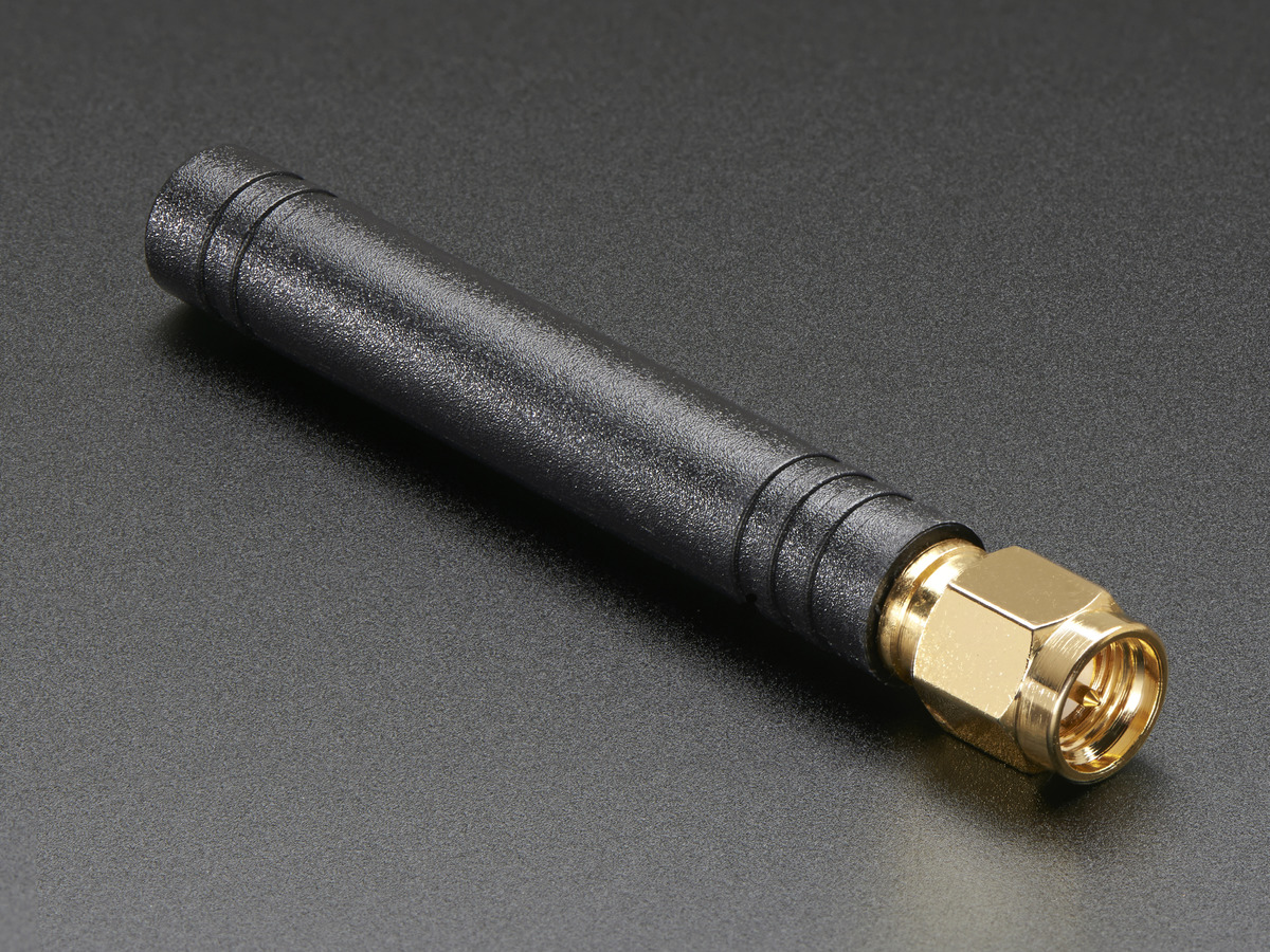
The antenna shown in Figure 3 is a 2.4” long antenna with a gain of 2dBi and an impedance of 50 ohms. It is compatible with any 850/900/1800/1900/2100 wireless receiver/transmitter. From the datasheet of the component, the specifications are found to be:
- Frequency: 850/900/1800/1900/2100 MHz
- Gain: 2 dBi
- Voltage Standing Wave Ratio => 2:1
- Polarization: Vertical
- Connector: SMA Male (Option)
- Impedance: 50Ω
Design and Approach
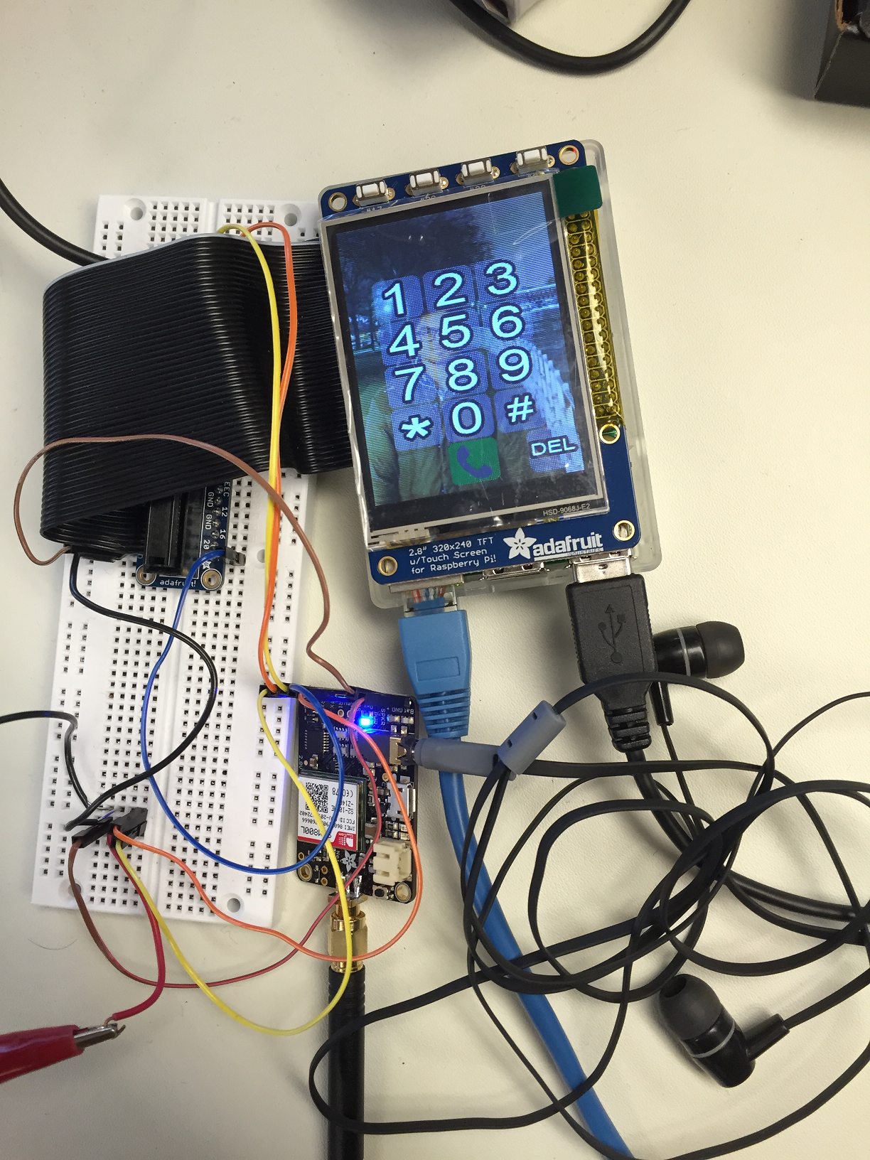
The design of 'Embedded Phone' is motivated by an already existing project called PiPhone[1]. We incorporate the PiPhone as the baseline version to design. This design serves as a good baseline as there is a lot of scope for improvement. The PiPhone only has functionality to make a phone call but it does not have functionality to receive any phone call. So, we take an incremental design approach and design the phone to make phone calls first. Then, we add the functionality to receive the phone calls. In addition, we tried to see if the Embedded Phone is functional when we run it on a real-time kernel. Figure 4 shows the complete setup of the Embedded Phone.
Figure 4: Embedded Phone setup
The hardware schematic for interfacing the GSM FONA module with the Raspberry Pi is depicted in
Figure 8 in the Drawings section.
Baseline Design
Touchscreen Setup
First, the PiTFT touchscreen has to be setup if it is not already done so. Since we already have the
PiTFT setup from the lab we don't need to do it again. But, the screen has to be rotated from landscape
to portrait view so that all the numbers are visible on the PiTFT when the dial screen loads.
Communication Setup
Then, we should make the serial port of the RaspberryPi available so that the Pi can communicate with
FONA module. By default, the GPIO pins Raspberry Pi are setup such that serial communication is used
by another process.
Since we want FONA to communicate with the Raspberry Pi over the serial port, we have to disable it to
allow for the Embedded phone to easily utilize serial communication by importing the "serial" Python
library. For enabling the Python script to have access to the serial communication GPIO pins, the '/etc/inittab' file must be modified, and the following line must be commented.
- T0:23:respawn:/sbin/getty -L ttyAMA0 115200 vt100
Software Setup
For the baseline design, we clone the Python scripts and icons of from PiPhone provided by David Hunt[1] on
Github. In the Python script, the Icon and button classes are defined. When the application starts running,
everything is initialized first before
PyGame is started, and the buttons are loaded on to the screen. For each button press on the PiTFT, a callback
function is called. The callback functions reacts to the trigger or, in this case, a button press. If the
hangup button
is pressed, the Embedded Phone hangs up the call. If a number is pressed, that number is printed on the screen
and if 'delete' button
is pressed, it clears one digit on the screen and so on.
Debugging with Minicom
Minicom is a text-based serial port communications program. It is used to talk to external RS-232 devices
such as mobile phones,
and serial console ports. We make use of minicom to check if the serial communication between Raspberry Pi
and FONA is taking place
correctly. To ensure that serial communication between the Pi and FONA are established, we open up minicom using the command
- %sudo minicom -D /dev/ttyAMA0 -b 115200
Then, to check if the serial communication from FONA is correctly received by the Pi, few 'AT' commands are issued and if 'OK' is received, then the communication is proper. To make a phone call, command 'ATD'+(phone number) has to be sent to the FONA. After the baseline design is setup and making sure that the communcation between the Pi and FONA are established, a GSM SIM is inserted in the FONA. We check the network status LED to make sure that the network connection is establised. Then, we tested the setup by plugging in a headset and dailing a number. After making sure that the baseline version is working, we move on to adding more functionality to the Embedded Phone.
Additional Functionality
After testing the baseline design, we add the functionality to receive incoming calls on the Embedded
Phone. There are a few things we need
to do inorder to acheive this. As described in the list of components sub-section, RI is an output
interrupt pin on the FONA module
which is by default high and pulses low for 120ms when there is an incoming phone call. We leverage
this pin and connect it to
a GPIO pin on the RaspberryPi which is set as an input pin. Falling edge on the GPIO pin calls a callback
function which changes screen mode.
The baseline design only had two screen modes, and it would switch between back and forth. Now, we create
two more screen modes to display the incoming
call number and if the call is connected or not.
So, there are four screen modes in our design. They are
- Screen Mode 0: Home screen with 0-9,*,#,call and del buttons
- Screen Mode 1: Dialing screen with outgoing number displayed and hangup button
- Screen Mode 2: Incoming screen with incoming number displayed and call button
- Screen Mode 3: Connected screen with phone number and hangup button
The transitions from one screen mode to another are shown in the state diagrm in Figure 6.
Figure 6: Screen mode Transition Diagram

From the state diagram in figure 6, it can be seen that state is changed to screen mode 2 when a call is received. Then, pressing the call button in this screen will call a callback function which sends "ATA" command serially to the FONA which is the command for answering the call. It also changes the state to screen mode 3 which shows that the call connection is established.
Challenges in screen mode 2
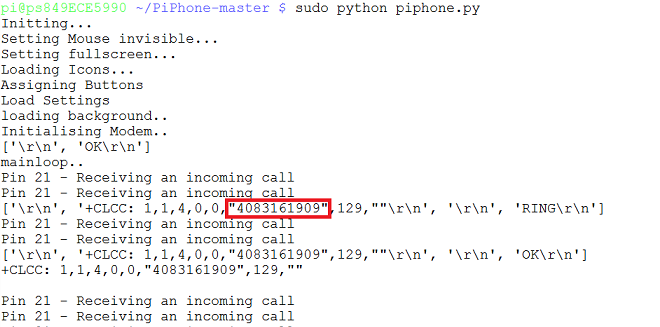
In screen mode 2, when an incoming call is received, the incoming number is displayed on the screen. To obtain the number, we send "AT+CLCC" command to the FONA. In response to this command, FONA sends a list of strings in which the phone number is in one of the strings. Figure 7 shows our debug screen showing response FONA gives when a "AT+CLCC" command is issued. The phone number is highlighted in red. In this screen mode, the phone number is extracted from this list of strings and then printed on the screen. Initially, there was a lot of delay in switching from screen mode 0 to 2 when an incoming call is received. This is due to the processing of the response sent by FONA to extract the phone number before switching the screen mode as well as the multiple calls to the interrupt callback handler by the Ring Indicator. Displaying the number as soon as receive an incoming call is very essential in a phone. We tackled this problem efficiently by extracting the number in the main computation loop instead of processing it in the callback routine which was our initial idea.
Figure 7: Debug Screen
Testing
We incrementally added each feature and tested if the added feature is working before moving on to adding the next feature. For instance, in screenmode 2, the phone number was displayed in the early stages of the design. After making sure that screen mode transitions from 0 to 2 when there is an incoming call, we then worked on displaying the phone number. Then, the transition from mode 2 to 3 is designed. The functionality of the Embedded Phone is throughly tested by making and receiving calls several times through out the design process. In addition, we utlized minicom to help monitor the messages passed between the GSM module and the Raspberry Pi.
Drawings top
Figure 8: Hardware Schematic showing connections between RaspberryPi and FONA
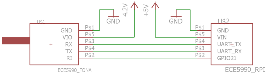
Figure 8 depicts the connections between FONA and the Pi. TX and RX pins of FONA are connected to RX and TX pins of Pi, respectively. One important thing to notice in the above schematic is the supply voltage to VIO pin on FONA. Although the datasheet specifies the range to be 3-5V, FONA did not power up when 5V was provided to it. The GSM module only powered up when voltage supplied was reduced to 4.2V. Both the grounds are connected together. Ring Indicator (RI) is connected to GPIO 21 of the Pi.
Results top
The Embedded Phone has been tested and can successfully make outgoing and receive incoming calls. When the application is launched, a dial screen with buttons 0-9,*,#,call,del, and hangup are loaded. A headset with a microphone is connected to the 3.5mm headset on the FONA. Depending on whether the Embedded Phone is making an outgoing or receiving an incoming call, corresponding callback functions are called to send approriate commands to send to the FONA (ATD - to call, ATA - to answer, ATH - to hang up), and the screen mode adjusts corresponding to the state. The figures below illustrate different screen modes on the phone.
Figure 8 : Dial and calling screens on the Embedded Phone
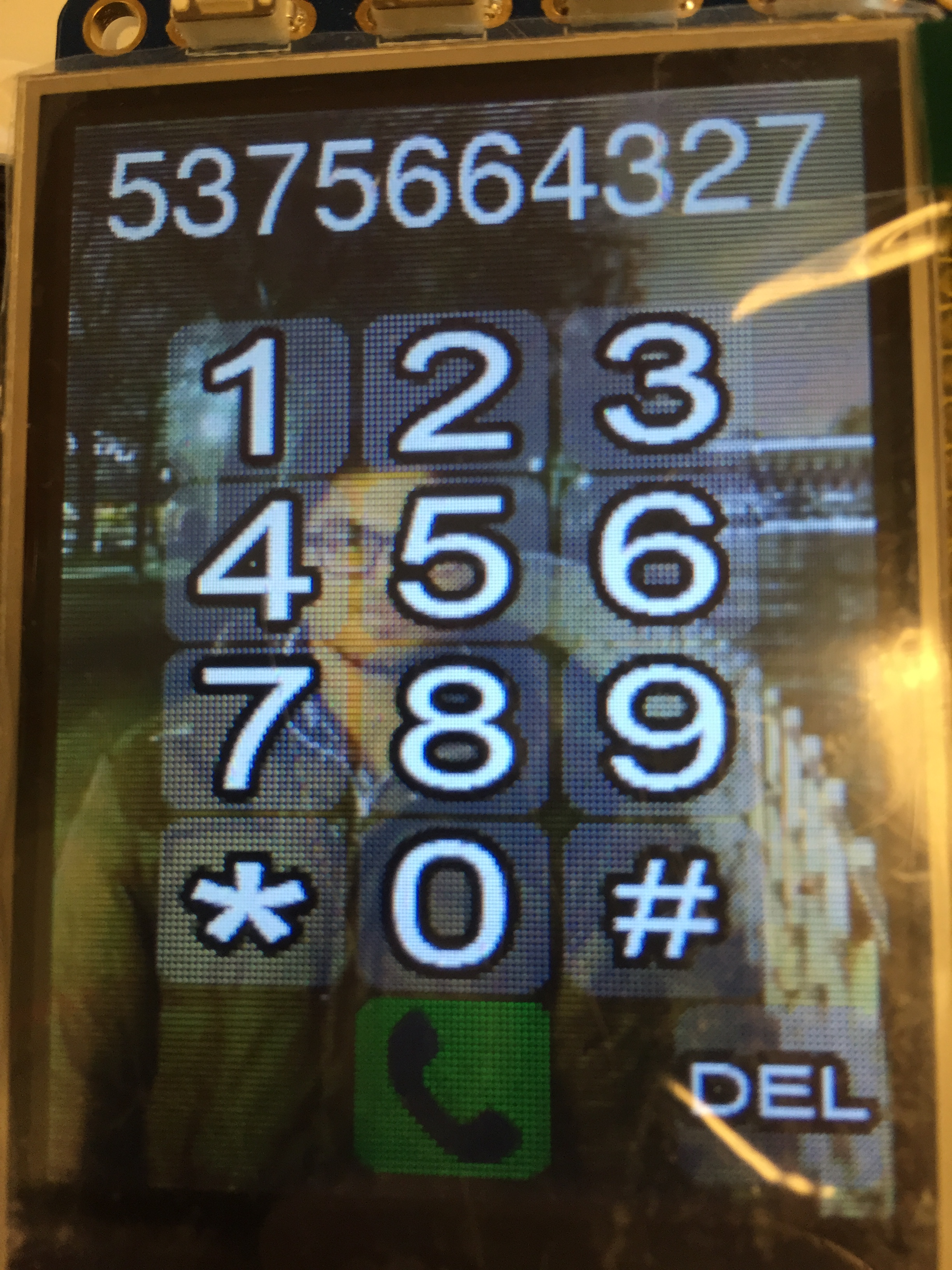
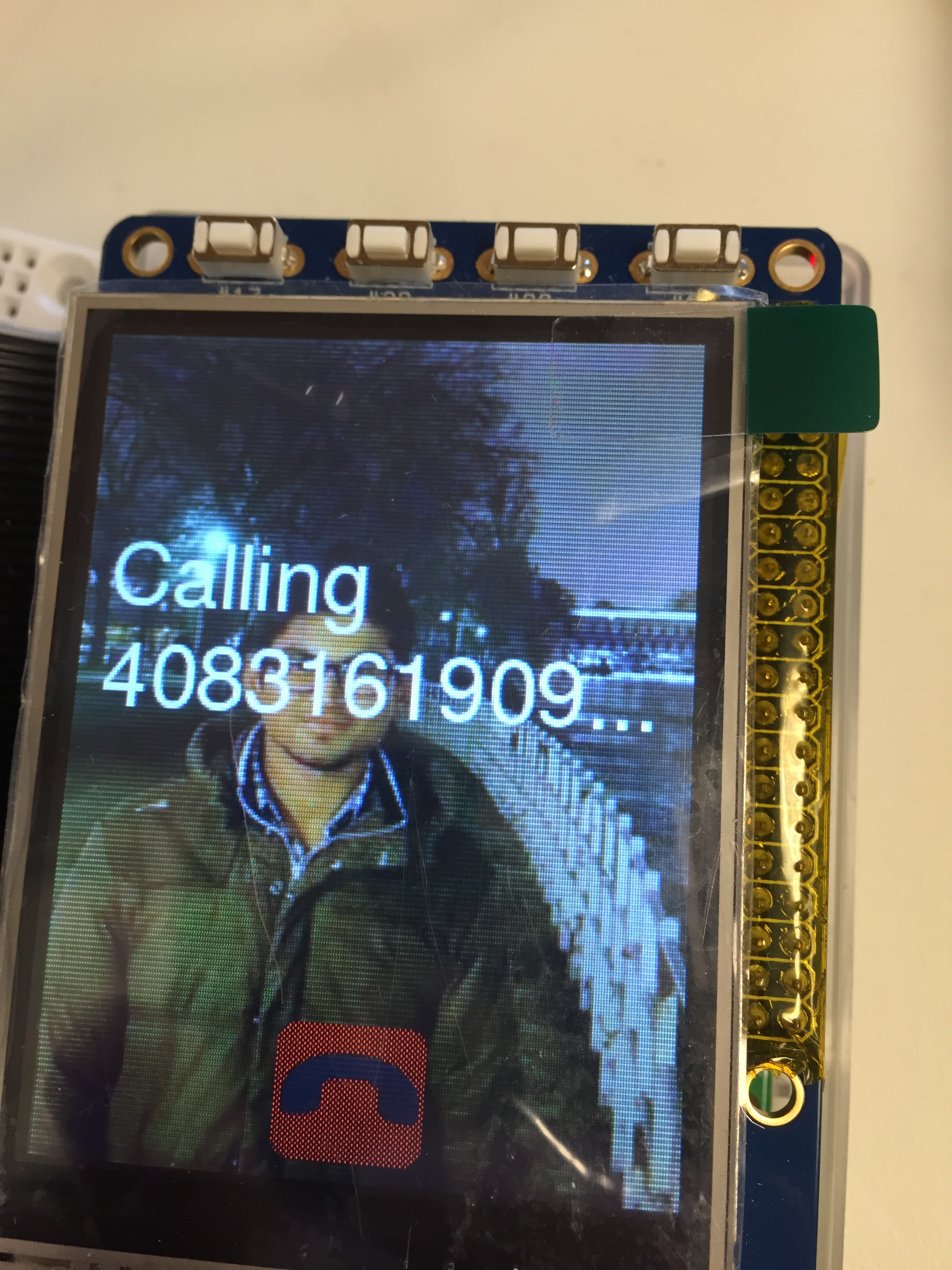
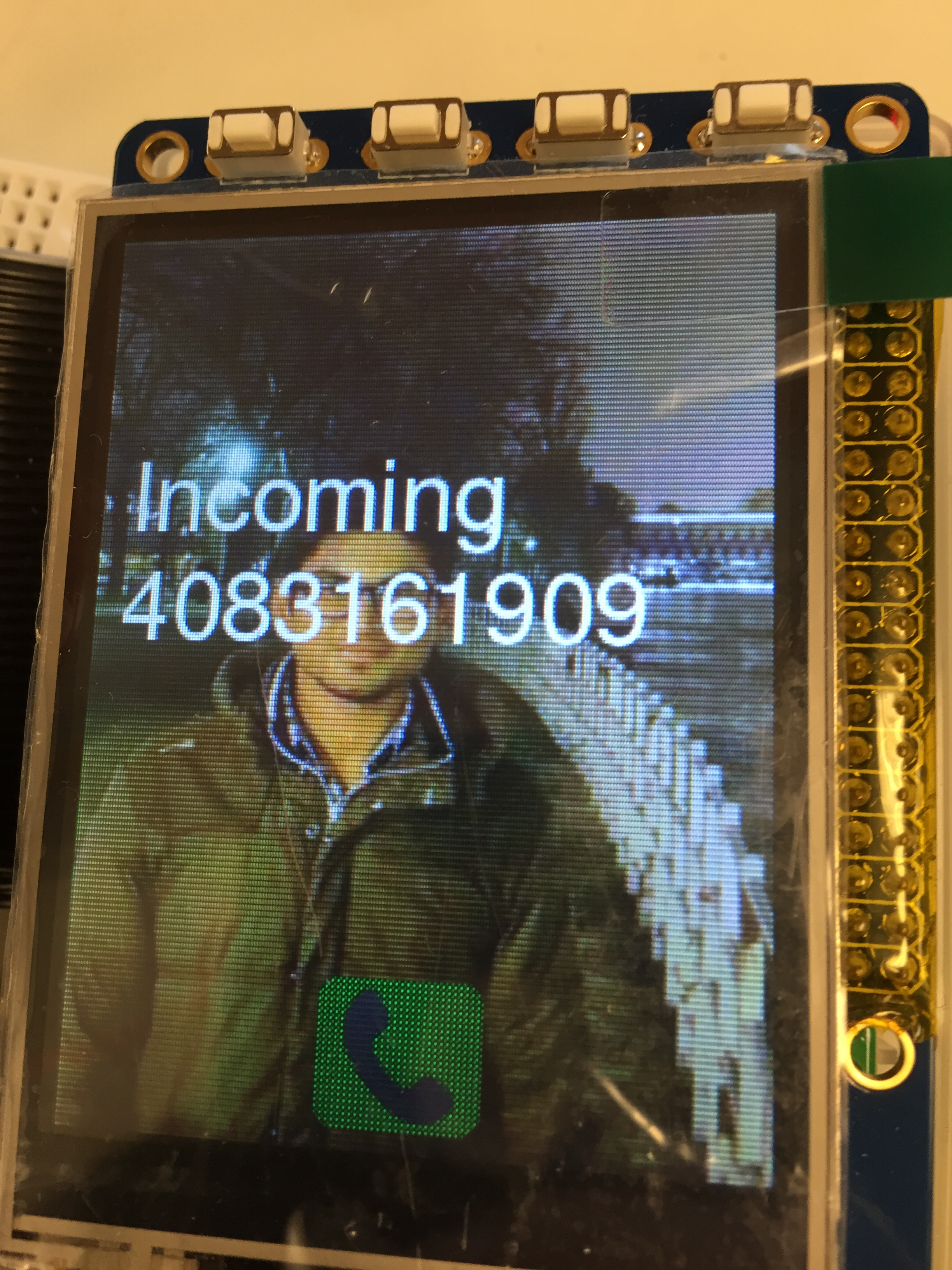
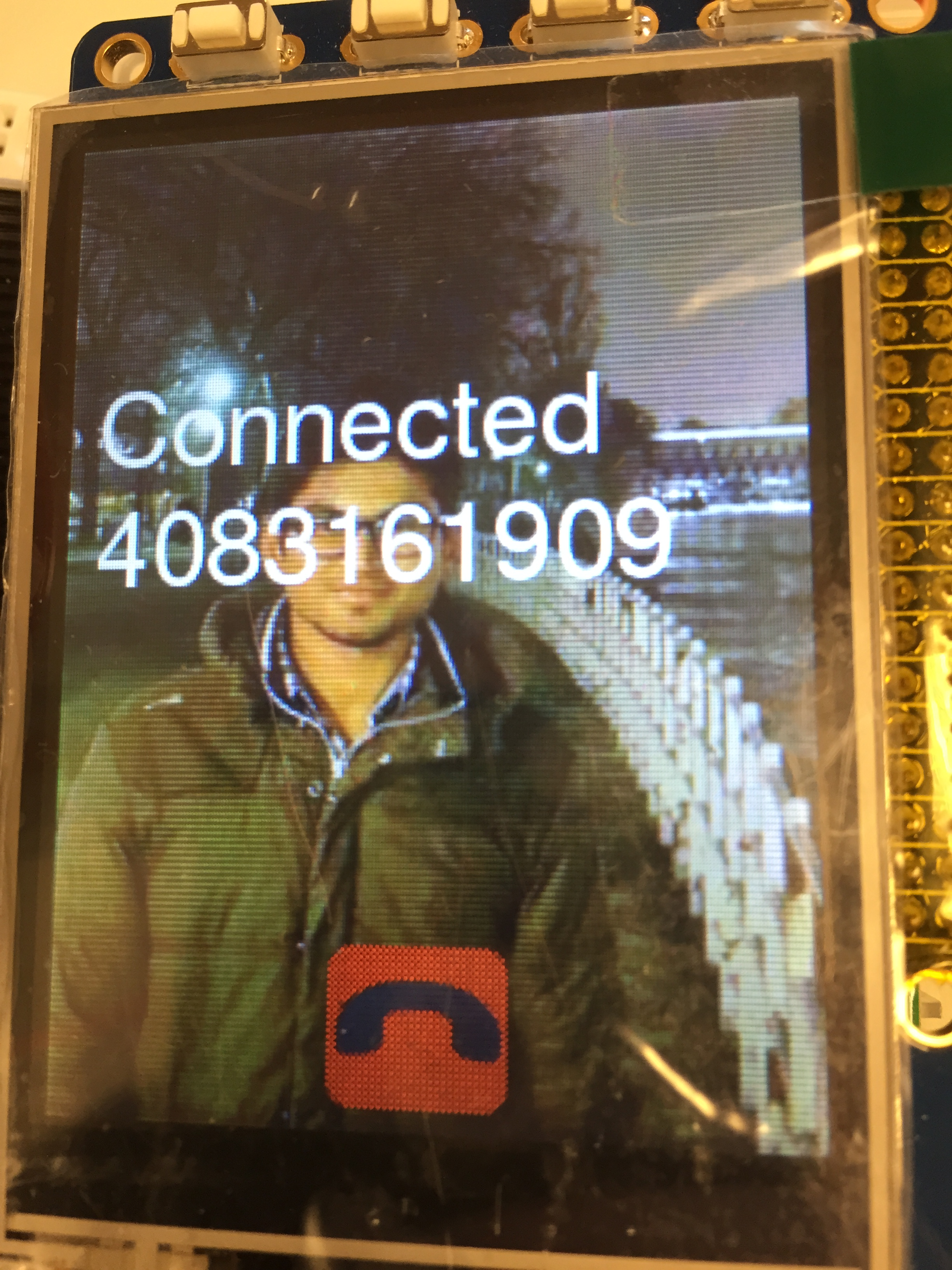
Figure 9: Incoming and call connected screens on the Embeddded Phone
Video 1 - Demo
An Attempt with running Embedded Phone on Real-Time Linux kernel
We tried to check if this application would run without issues on an RT-kernel to compare the performance of the application on both the kernels. For this purpose, we used the precompiled version of RT-kernel which was provided to us in lab3. Since touchscreen was not installed on this kernel, we installed the touchscreen on this kernel and set the orientation to portrait mode. Then, we tried running the Embedded Phone application on this kernel. However, we noticed that it does not function properly on RT-kernel. When we launch the program, the buttons are loaded on the screen correctly, and the PiPhone appeared to be functional. However, the user interface and functionality was not the same as that of non-RT kernel. The button press input provided on the touchscreen were not interpretted properly. Also, the Embedded Phone experienced significant amounts of delay. Afterwards, although the button for key '1' was pressed, a '3' would be recorded multiple times. To debug this step, we utilized print commands that demonstrated the Raspberry Pi was receiving multiple key presses for every touch. When attempting to fix this issue, other parts of the code continued to fail. First, the Embedded Phone failed to load anymore even after removing any and all changes to the file. Next, the "readlines" command for the serial port outputting and error. Removing and modifying the command to a different "read" command also did not prove to be fruitful, and we began implementing checks to monitor whether the serial receiver buffer had any data before reading. The Embedded Phone still created an error whenever the read command was called.
As a result, the next step was to evaluate the FONA GSM module with minicom. For the non-RT kernel, minicom was beneficial for helping us debug and test serial commands, but for the RT kernel, minicom failed to output proper results. Not only did the values continuously overwrite itself, but also minicom was not displaying the write values. The output was full of line breaks and often times, only had one seemingly random character per line. However, there were moments when the minicom would stop printing random characters but would repeatedly overwrite the same line with "login failed". After switching the SD card to utilize a non-RT kernel, we ensured that the settings for minicom were the same as that used for RT kernel, but minicom running on the non-RT kernel was performing well and was completely functional.
Next, we tried with the pre-compiled RT kernel provided on the course webpage. Unlike the previous RT kernel used, this version only has the basic Raspberry Pi setup, so we had to install the TFT screen. Even after following the steps used in Lab 1, we successfully configured the Raspberry Pi such that the TFT screen is the used instead of an external monitor; however, the touch events were not properly being recorded or handled. Even after reinstalling X11 server and xf86 modules for the display and the touch events, the touchscreen was still not functional. Therefore, we were not able to find a way to properly execute the Embedded Phone on a real-time kernel. In fact, we could not even obtain consistent, repeatable errors, which made debugging more difficult. However, our application performs well on the non-RT Linux kernel.
Conclusions top
Conclusion
In conclusion, we developed an Embedded Phone which is inspired by David Hunt's PiPhone[1]. Embedded Phone is designed using RaspberryPi, PiTFT touchscreen, FONA GSM Module and Mini GSM Quad-Band Antenna. Using the UART serial communication, the Raspberry Pi communicates with FONA to answer the calls, dial or hang up a call. Embedded Phone has basic functionality to make outgoing and receive incoming calls. Upon execution of the application, the dial screen loads up. There are 4 screen modes in our design for dialing, incoming call, calling, and connected states. One nice feature which we added to the phone is displaying the number when there is an incoming call. We tested the design by calling the phone and making calls from the phone. We noticed that there is static noise in the signal when a call is established. There is a possibility to improve the design by filtering out the noise at the earphone jack. Finally, we attempted to execute the program on a real-time kernel to check to see if we can get any performance improvements. Upon testing, we noticed that there is significant amount of lag in detecting the touch input and the touch input is not detected correctly. We believe that this is caused by the real-time linux scheduler, but we were not able to adapt the program to make it run on the real-time kernel. However, our Embedded Phone runs on the non real-time kernel with minimum delays to switch between the screen modes or states. Finally, this project helped us in putting a lot of concepts learned in the class to practice. We used pygame to load buttons which was introducted early in the semester as well as utilizing interrupts and callback routines which we've been using in all the labs. We also tried our application on real-time kernel, and we see that it doesn't work well on the real-time kernel possibly due to the fact that our application is in Python, which is not very suitable for real-time systems and to real-time linux scheduler.
Future Work
One improvement for the Embedded Phone is to have the code functional with the real-time patch. Although we were not able to find the solution to allow our code to execute properly, a functional prototype would allow us to discover any performance increase by executing with a real-time kernel because the real-time kernel has demonstrated to have a performance boost when evaluated with cyclictest or with a simple blinking LED test. It has been shown to reduce the worst-case latency of program. In addition, Python is not optimal for running real-time systems where scheduling is involved; therefore, another improvement would be to rewrite the program with C or C++, which is a more lightweight language. In addition, SDL instead of PyGame would be used for C++, which would also improve the efficiency and reduce any lag that the Embedded Phone has. In addition, we can add more functionality to the Embedded Phone, such as text messaging and storing contact information.
Appendices top
A. Code Listing
B. Cost Analysis
In our project, we made use of lab components listed below. The following projects listed below were provided by the class and are not factored into our budget requirement.
| Lab Components Used | Price ($) |
| Raspberry Pi 2 Model B | 35 |
| 2.8 Inch PiTFT Screen | 35 |
| GPIO 26 Pin Ribbon Cable | 5 |
| White Breadboard | 5 |
| Wires, Resistors, Misc | - |
| Total | 80 |
The additional components that were purchased for this project are listed below. The total cost of the components purchased is well within the budget allocated for this project ($75).
| Components Purchased | Quantity | Vendor | Price ($) |
| FONA GSM Module | 1 | Adafruit | 44.95 |
| Mini GSM Quad-Band Antenna | 1 | Adafruit | 4.95 |
| Total | 49.9 | ||
C. Division of Labor
The initial hardware setup and soldering work required was done by Pawan while Rex experimented with the PiPhone script from David Hunt's blog[1]. Both Rex and Pawan worked on implementing the initial version of the design, which only included functionality to make a call. By working together, we had the same understanding of how the original PiPhone works and what needed to be done for modification. Then Rex started working on adding more features to improve the usability of the Embedded Phone, such as receiving incoming phone calls. In addition, he created and implemented the state machine for the Embedded Phone to improve reliability as well as decrease the latency.
In parallel, Pawan was loading the precompiled RT kernel from Blackboard. Because the RT kernel did not have TFT display capabilities, he returned to the Lab 1 instructions to install and calibrate the touch screen. Because this step was not fruitful, Pawan flashed the pre-compiled RT kernel from Lab 3, and Pawan began testing the original PiPhone application on the real-time kernel. Next, he began debugging to find a solution for the errors resulting from executing the Python script and the serial commands. He learned to utilize minicom as a form of debugging to attempt to determine the cause of the errors. However, since a solution has not been found, Rex and Pawan attempted to solve the problem by working together to debug the application running on the RT kernel.
Pawan began documenting the Embedded Phone as Rex continued to debug the application on the RT kernel. Finally, for the report, Pawan worked on design, results, and cost analysis sections while Rex setup the HTML template, created the schematics/bloc diagrams, and completed the writing for the remaining sections. Then, both of us edited the report for a final version.
References top
- “PiPhone - A Raspberry Pi based Smartphone,” wwwDavidHuntie PiPhone A Raspberry Pi based Smartphone Comments, 2014. [Online]. Available at: http://www.davidhunt.ie/piphone-a-raspberry-pi-based-smartphone/. [Accessed: Aug-2015].
- “PiPhone - A Raspberry Pi based Cellphone,” Overview. [Online]. Available at: https://learn.adafruit.com/piphone-a-raspberry-pi-based-cellphone/overview. [Accessed: Aug-2015].
- “SIM800 Series_AT Command Manual_V1.01,” 2013. [Online]. Available at: https://www.adafruit.com/datasheets/sim800_series_at_command_manual_v1.01.pdf. [Accessed: Aug-2015].
- “Mini GSM/Cellular Quad-Band Antenna - 2dBi SMA Plug,” adafruit industries blog RSS. [Online]. Available at: https://www.adafruit.com/products/1859. [Accessed: Aug-2015].
- M. Hawkins, “Simple Guide to the RPi GPIO Header and Pins,” Simple Guide to the RPi GPIO Header and Pins, Sep-2012. [Online]. Available at: http://www.raspberrypi-spy.co.uk/2012/06/simple-guide-to-the-rpi-gpio-header-and-pins/. [Accessed: Sep-2015].
Acknowledgements top
We would like to thank Professor Joseph Skovira for his patience and his advice regarding this project. Although we had difficulty allowing the Embedded Phone to execute the python script on the real-time patch, he provided help with anything that we needed. In addition, we would like to thank our TA Gautham for always being available to answer our questions.