ECE5725 Project
Laser Projector
Haotian Tan and Weixuan Sun.
Demonstration Video
Introduction
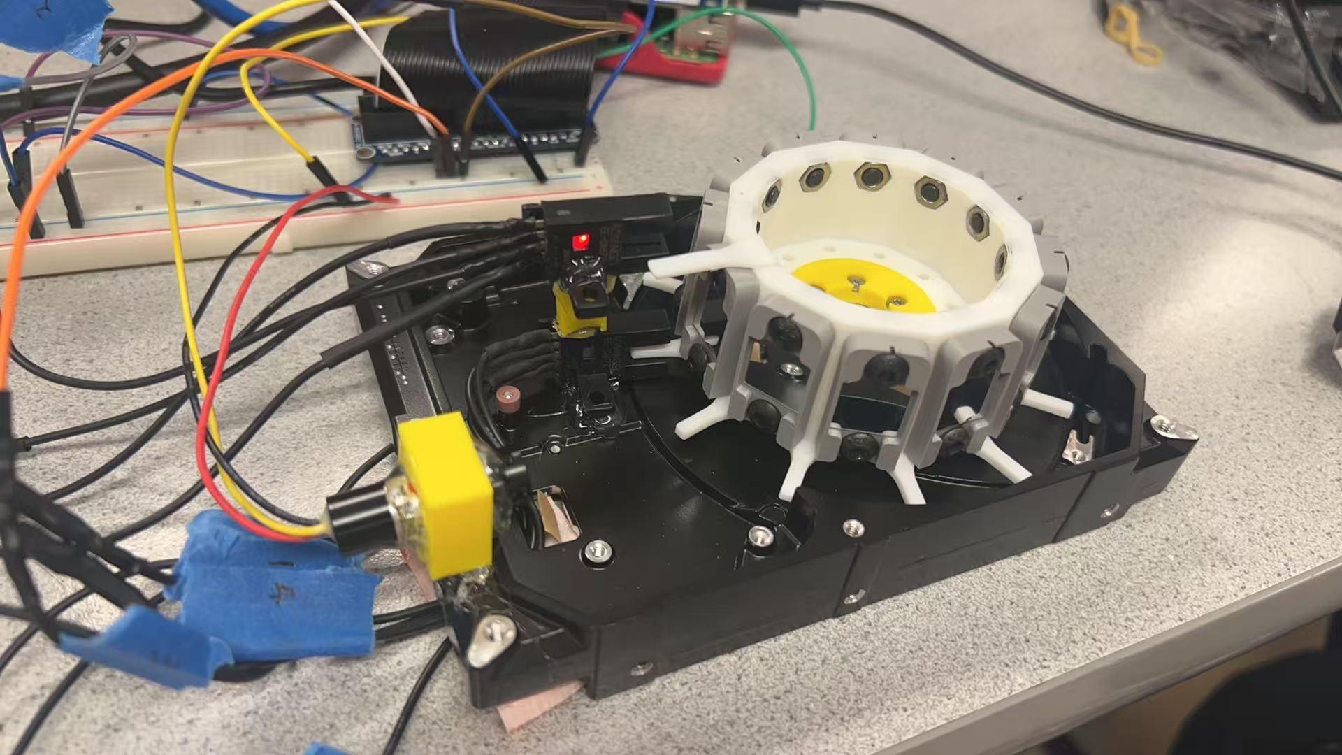
In this project, we built a simple laser projector using a point-source laser and the idea of persistence of vision to display frames. Our setup includes a spinning disk with 12 small mirrors mounted on it, and the whole thing is driven by a brushless motor taken from an old HDD. Each mirror represents one scan line, so as the disk spins, we turn the laser on and off at the right times to "draw" an image line by line. When it spins fast enough, your eyes blend the flashing points into a full image. It's a minimal and fun way to make a working laser display.
Project Objective:
- Build a low-cost laser projector using basic components (e.g., HDD motor, laser diode, mirrors)
- Use persistence of vision to display simple static images
- Design and assemble a spinning mirror system with 12 reflective surfaces, each representing one scan line
- Control the laser to turn on and off at the right times to create a full image
- Synchronize laser pulses with mirror rotation to "draw" images line-by-line
Design
Motor Testing
We started the project by designing our system based on a YouTube reference and initially selected a 2.5" HDD as the base for our spinning mirror array. At the same time, we began testing key components such as the point-source laser and infrared (IR) break beam sensors to validate their responsiveness and alignment. However, during early trials, we discovered that the motor from the 2.5" HDD did not provide enough torque to reliably spin our 3D-printed spinner, which included 12 mounted mirrors. As a result, we switched to a 3.5" HDD, which offered stronger torque and better mechanical stability.
Once the mechanical structure was functioning, our next challenge was maintaining a consistent motor speed. The built-in motor controller in the HDD had power-saving features that caused it to stop spinning after a short period. We tried to keep the motor active by connecting the HDD to a Raspberry Pi via USB and simulating continuous data transfer. However, this method failed because we had removed the read/write head to fit our spinner, which made the HDD unrecognizable as a functional storage device.
We also experimented with rapidly power-cycling the HDD using software, trying to trick it into staying on. This approach was unstable, as the motor took varying amounts of time to spin up each time. Even with minimal delay between cycles, we could hear inconsistent acceleration and deceleration, which made it impossible to maintain stable speed.
To resolve this, we purchased a simple ESC (electronic speed controller) that allowed us to adjust the motor speed manually using a built-in knob. While this ESC could not be controlled programmatically through PWM, it gave us much more consistent and reliable control over the motor’s speed compared to our earlier attempts. This adjustment was crucial for achieving smooth mirror rotation and consistent laser timing during projection.
Spinner
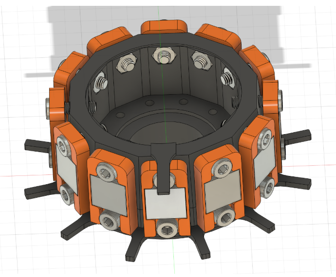
3D Drawing of Spinner
The 3D model of the spinner includes 12 mirrors mounted on adjustable holders. Each holder is secured with screws at the top and bottom, allowing for fine-tuning of the mirror angles. At the base of the spinner, there are 12 evenly spaced teeth—one for each mirror—which are used to identify the current mirror position during rotation. Additionally, a single tooth at the top of the spinner serves as a reference point to reset the count back to the first mirror. The bottom and top teeth are detected using IR break beam sensors, which allow the system to synchronize laser pulses with mirror positions.
IR Sensors
We connected the infrared (IR) break beam sensor to a 5V power supply, and its output was connected to one of the GPIO pins on the Raspberry Pi (or Arduino, depending on the setup). The sensor outputs a digital signal that changes state when an object (in our case, a tooth on the spinner) interrupts the IR beam.
We mounted 12 evenly spaced teeth on the bottom of the spinner—one for each mirror—and a single tooth on the top to serve as a reference point. The bottom sensor detects each of the 12 teeth, allowing us to track which mirror is currently in position. The top sensor detects the single reference tooth, which serves as a reset signal to synchronize the system back to the first mirror.
We used a callback function to monitor the GPIO input and respond immediately when the sensor signal changed. The action is also done using DMA techniques. Each time the bottom sensor is triggered, we increment a mirror index counter. When the top sensor is triggered, the counter is reset to zero. This way, we can precisely synchronize the laser pulses with the corresponding mirror positions during each rotation.
During testing, we initially avoided setting up laser pulses inside the main loop. Instead, we preloaded them during initialization and ensured the laser fired immediately when the bottom IR breaker was triggered. We also tried raising task priority, but none of these approaches worked reliably. Eventually, we switched to using an Arduino for laser control, which resolved the timing issues.
This sensing mechanism provides a reliable way to track the spinner's position in real time and ensures each mirror gets triggered at the right moment for image projection.
Laser Projector System
Despite our efforts, we were unable to achieve a stable projected line using the Raspberry Pi. We attempted to raise process priority and use DMA to reduce laser onset delay, but the system remained unstable due to the non-real-time nature of the Linux operating system.
We then switched to using an Arduino for laser control and immediately observed a steady, consistent line on the screen. This improvement can be attributed to Arduino’s real-time behavior, which eliminates the delays and unpredictability associated with multitasking operating systems.
Result
We were able to build a working system that successfully fired the laser and produced distinguishable scan lines. However, we encountered a major limitation with the Raspberry Pi: it could not maintain a stable and consistent timing signal required for smooth projection. As a result, the projected image lacked steadiness.
To address this issue, we looked into a previous project that used a hybrid setup—an Arduino was responsible for precise laser timing and projection, while the Raspberry Pi handled calculations and higher-level control. Inspired by that approach, we switched to using an Arduino for the laser triggering logic. So far, we have tested the system with a single-line projection and confirmed that it functions correctly under Arduino control.
Work Distribution
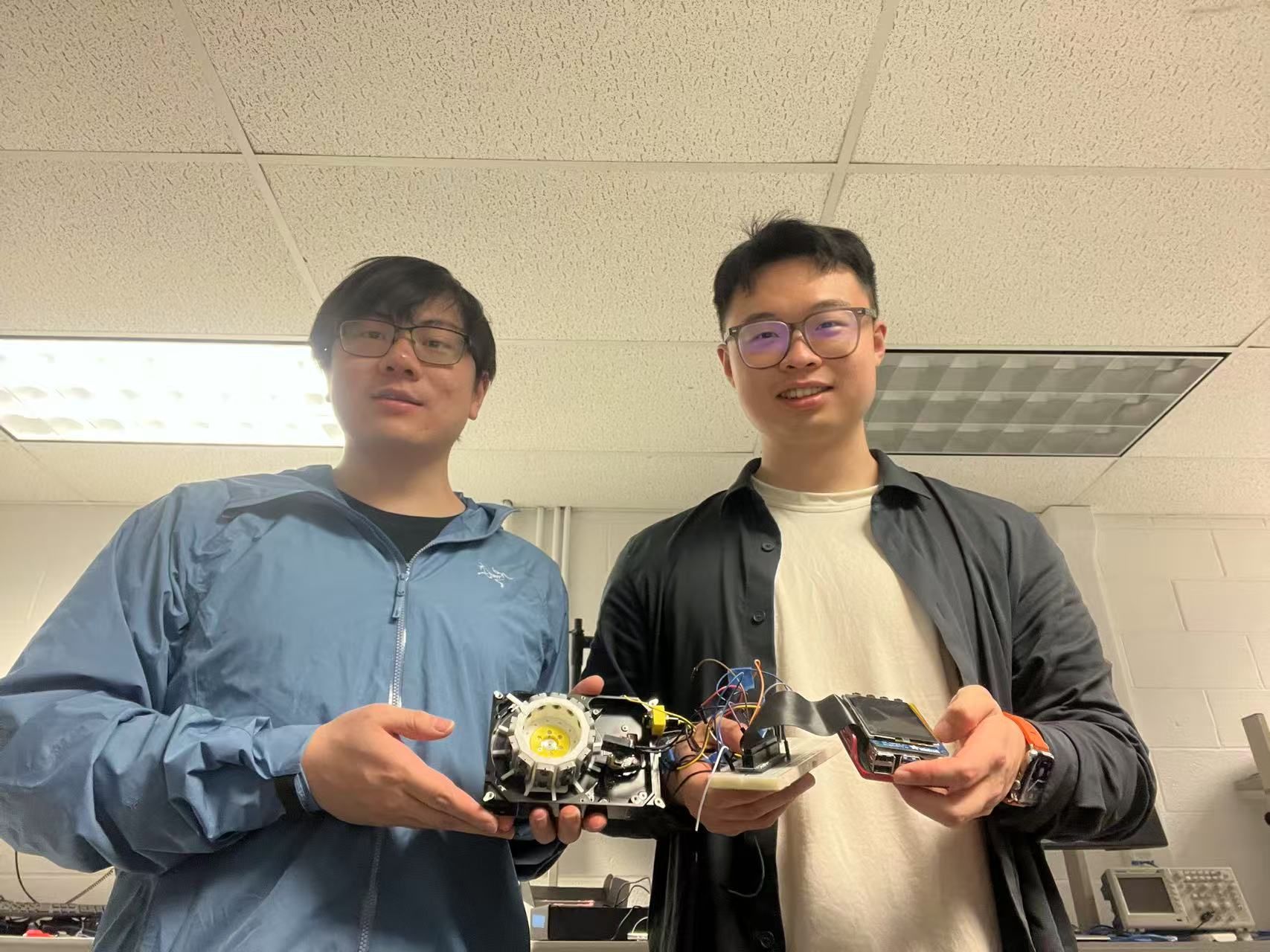
Project group picture

Haotian Tan
ht499@cornell.edu
Hardware design and assembly, including the spinner and mirror holders. I also worked on the motor control system, including the ESC setup and initial testing of the laser projection system.

Weixuan Sun
ws495@cornell.edu
Software Architecture and Design, including the initial setup of the Raspberry Pi and the development of the laser control logic. I also worked on the integration of the IR sensors and the synchronization of the laser pulses with the mirror positions.
Parts List
| Parts | Quantity | Unit Price | Total Price |
|---|---|---|---|
| Raspberry Pi 4 | 1 | $35 | $35 |
| Arduino | 1 | $27.5 | $27.5 |
| Laser | 1 | $6 | $6 |
| IR Breaker | 2 | $4 | $8 |
| 3.5” HDD | 1 | N/A | N/A |
| ESC Driver | 1 | $20 | $20 |
| Total Price | $96.5 |
References
- ECE5725 Final Project: Laser Projector (Fall 2017). https://courses.ece.cornell.edu/ece5990/ECE5725_Fall2017_projects/bt346-qq39/
- Omron EE-SX47/67 Infrared Sensor Datasheet. https://www.ia.omron.com/data_pdf/cat/ee-sx47_67_ds_e_13_4_csm483.pdf
- Persistence of Vision Explained – How Our Eyes Trick Us. https://www.explainthatstuff.com/how-persistence-of-vision-works.html
- Using ESCs with Brushless Motors – RCBasics. https://www.rchelicopterfun.com/brushless-motor-esc.html
- Arduino External Interrupts Tutorial. https://www.arduino.cc/reference/en/language/functions/external-interrupts/attachinterrupt/
- pigpio Library for Raspberry Pi GPIO Control. http://abyz.me.uk/rpi/pigpio/
Code Appendix
RPI
#!/usr/bin/env python3
# Lab Section: Monday Group 4
# Date       : 05/16/25
# Members    : Haotian Tan(ht499), Weixuan Sun(ws495)


import os, sys, time, math, collections
import pigpio, pygame


BTM_PIN, LASER_PIN                  = 27, 4
BTN_UP_PIN, BTN_DN_PIN, BTN_QT_PIN = 17, 22, 23


FACETS_PER_REV = 12
AVG_SAMPLES    = 12
FPS            = 30
SWEEP_SCALE    = 0.10
DUTY_STEP      = 0.01
STALL_MS       = 500
SLIDER_H, SLIDER_M           = 20, 20


# pigpio initialisation
pi = pigpio.pi()
if not pi.connected:
    sys.exit("pigpiod not running – start with: sudo pigpiod")


for pin in (BTM_PIN, BTN_UP_PIN, BTN_DN_PIN, BTN_QT_PIN):
    pi.set_mode(pin, pigpio.INPUT)
    pi.set_pull_up_down(pin, pigpio.PUD_UP)  # buttons are active‑LOW


pi.set_mode(LASER_PIN, pigpio.OUTPUT)
pi.write(LASER_PIN, 0)  # laser starts OFF


# PiTFT setup
os.environ.setdefault("SDL_VIDEODRIVER", "fbcon")
os.environ.setdefault("SDL_FBDEV", "/dev/fb0")
pygame.init(); screen = pygame.display.set_mode((0, 0))  # full‑screen
W, H = screen.get_size()


font_big   = pygame.font.SysFont(None, 40, bold=True)
font_small = pygame.font.SysFont(None, 26)
WHITE, GREEN, GREY, BLACK = (255,)*3, (80,255,80), (60,60,60), (0,0,0)


RADAR_C = (30, (H - SLIDER_H)//2)  # radar centre (x,y)
RADAR_R = 20                       # radar radius
TEXT_X  = RADAR_C[0] + RADAR_R + 10
TEXT_Y  = RADAR_C[1]


rows_us       = collections.deque(maxlen=AVG_SAMPLES)
last_tick     = None
last_edge     = time.monotonic()


duty          = 0.0
pulse_us      = 0
rpm           = 0.0
row_us        = 0.0


btn_up = btn_dn = False
running = True
current_wave = None


# Graphics helper
def draw(angle: float) -> None:
    screen.fill(BLACK)


    # radar sweep
    end = (RADAR_C[0] + RADAR_R*math.cos(math.radians(angle)),
           RADAR_C[1] + RADAR_R*math.sin(math.radians(angle)))
    pygame.draw.circle(screen, GREY, RADAR_C, RADAR_R, 1)
    pygame.draw.line(screen, GREEN, RADAR_C, end, 2)


    # RPM + period text
    hud = font_big.render(f"{rpm:6.1f} RPM   {row_us:7.1f} µs", True, WHITE)
    screen.blit(hud, hud.get_rect(midleft=(TEXT_X, TEXT_Y)))


    # duty slider
    slider = pygame.Rect(SLIDER_M, H-SLIDER_H-8, W-2*SLIDER_M, SLIDER_H)
    knob_x = slider.left + int(slider.width*duty)


    pygame.draw.rect(screen, GREY, slider, 1)
    fill = slider.copy(); fill.width = knob_x-slider.left
    pygame.draw.rect(screen, GREEN, fill)
    pygame.draw.circle(screen, WHITE, (knob_x, slider.centery), SLIDER_H//2-2)


    label = font_small.render(f"Laser {duty*100:3.0f}%  ({pulse_us:4d} µs)", True, WHITE)
    screen.blit(label, label.get_rect(midleft=(slider.left, slider.top-24)))
    pygame.display.flip()


# measure the rotation time and helps to adjust the laser length
def facet_cb(_gpio, level, tick):
    global last_tick, rpm, row_us, last_edge, pulse_us, current_wave


    if level != pigpio.HIGH:  # ignore falling edges / noise
        return


    # period measurement
    if last_tick is not None:
        dt = pigpio.tickDiff(last_tick, tick)
        rows_us.append(dt)
        row_us = sum(rows_us) / len(rows_us)
        rpm = 60000000 / (row_us * FACETS_PER_REV)
    last_tick, last_edge = tick, time.monotonic()


    # stop previous wave
    pi.wave_tx_stop()
    pi.write(LASER_PIN, 0)


    # build and send new pulse to control the laser length dynamically
    if rows_us:
        pulse_len = int(rows_us[-1] * duty)
        pulse_us = pulse_len
        if pulse_len:
            seq = [pigpio.pulse(1<= 0:
                pi.wave_send_once(wid)
                current_wave = wid


pi.callback(BTM_PIN, pigpio.RISING_EDGE, facet_cb)


# turning the laser length up
def btn_up_cb(gpio, level, tick):
    global btn_up
    if level == pigpio.LOW:     # button pressed
        btn_up = True
    elif level == pigpio.HIGH:  # button released
        btn_up = False


# turning the laser length down
def btn_dn_cb(gpio, level, tick):
    global btn_dn
    if level == pigpio.LOW:
        btn_dn = True
    elif level == pigpio.HIGH:
        btn_dn = False


# quit button
def btn_qt_cb(gpio, level, tick):
    global running
    if level == pigpio.LOW:  # only act on press
        running = False


# register button callbacks for controlling laser length and quit
pi.callback(BTN_UP_PIN, pigpio.EITHER_EDGE, btn_up_cb)
pi.callback(BTN_DN_PIN, pigpio.EITHER_EDGE, btn_dn_cb)
pi.callback(BTN_QT_PIN, pigpio.FALLING_EDGE,  btn_qt_cb)


# Main loop
clock = pygame.time.Clock()
angle = 0.0


while running:
    clock.tick(FPS)                 # fixed frame duration


    if btn_up:
        duty = min(duty + DUTY_STEP, 1.0)
    if btn_dn:
        duty = max(duty - DUTY_STEP, 0.0)


    # zero readout if stalled
    if time.monotonic() - last_edge > STALL_MS/1000:
        rpm = row_us = pulse_us = 0


    # update radar sweep
    angle = (angle + rpm*6*SWEEP_SCALE/FPS) % 360
    draw(angle)


    for evt in pygame.event.get():
        if evt.type in (pygame.QUIT, pygame.KEYDOWN):
            running = False


Arduino:
#define TOP_PIN   2
#define BTM_PIN   4
#define LASER_PIN 3


const unsigned long PULSE_WIDTH_US = 1000;   // laser on time
const int  FACETS_PER_REV = 12;
const int  TARGET_INDEX   = 3;               // only one mirror on


int  facet_idx       = 0;
bool last_top_state  = HIGH;
bool last_btm_state  = HIGH;


void setup() {
  pinMode(TOP_PIN,  INPUT_PULLUP);
  pinMode(BTM_PIN,  INPUT_PULLUP);
  pinMode(LASER_PIN, OUTPUT);


  Serial.begin(115200);
}


void loop() {
  bool top_now = digitalRead(TOP_PIN);
  bool btm_now = digitalRead(BTM_PIN);


  // full revolution marker
  if (last_top_state == HIGH && top_now == LOW) {
    facet_idx = 0;
    Serial.println(F("new revolution"));
  }


  // mirror marker
  if (last_btm_state == HIGH && btm_now == LOW) {
    Serial.print(F("[BTM] mirror "));
    Serial.print(facet_idx);


    if (facet_idx == TARGET_INDEX) {
      Serial.print(F(" fire laser"));
      digitalWrite(LASER_PIN, HIGH);
      delayMicroseconds(PULSE_WIDTH_US);
      digitalWrite(LASER_PIN, LOW);
    }


    Serial.println();
    facet_idx = (facet_idx + 1) % FACETS_PER_REV;
  }


  last_top_state = top_now;
  last_btm_state = btm_now;
}
Arduino
#define TOP_PIN    2          // One full-rotation sync sensor
#define BTM_PIN    4          // Reflector-per-facet sensor (12 per revolution)
#define LASER_PIN  3
#define PULSE_WIDTH_US 1000
#define TARGET_INDEX 3        // Which facet index to fire the laser (0~11)

int trigger_count = 0;
bool last_btm_state = HIGH;
bool last_top_state = HIGH;

void setup() {
  pinMode(TOP_PIN, INPUT_PULLUP);
  pinMode(BTM_PIN, INPUT_PULLUP);
  pinMode(LASER_PIN, OUTPUT);

  Serial.begin(115200);
  Serial.println("Synchronized single-pulse laser test");
}

void loop() {
  bool current_top = digitalRead(TOP_PIN);
  bool current_btm = digitalRead(BTM_PIN);

  // If TOP sensor triggers (start of a full revolution), reset counter
  if (last_top_state == HIGH && current_top == LOW) {
    trigger_count = 0;
    Serial.println("[TOP] Reset trigger count");
  }

  // If BTM sensor detects a reflector facet
  if (last_btm_state == HIGH && current_btm == LOW) {
    Serial.print("[BTM] Reflector #");
    Serial.print(trigger_count);

    if (trigger_count == TARGET_INDEX) {
      Serial.print(" → Laser ON");
      digitalWrite(LASER_PIN, HIGH);
      delayMicroseconds(PULSE_WIDTH_US);
      digitalWrite(LASER_PIN, LOW);
    }

    Serial.println();
    trigger_count = (trigger_count + 1) % 12;
  }

  last_top_state = current_top;
  last_btm_state = current_btm;
}
AI Disclaimer
Portions of this report, including text formatting, content refinement, and code structuring, were assisted by AI tools to enhance clarity and presentation. All technical work, experimental setup, design, and testing were conducted by the project team. The use of AI was limited to support documentation and formatting, and does not replace original engineering efforts.