JOE-YRIDE
Spring 2025 ECE5725 Project
A Project By Keiry Gao (kg368) and Andrew Shim (ks875)
Demonstration Video
Introduction
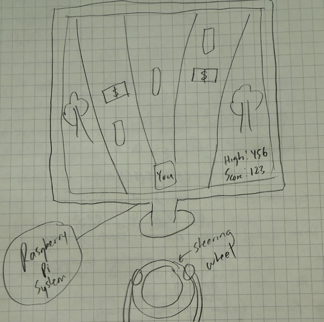
Driving simulation games are popular at arcades, but what if you could have a personal budget version of it at home? Using the Raspberry Pi 4 as our computer, we paired easily accessible components like a DC motor and a potentiometer with our custom 3-D printed steering wheel to build an engaging driving game with a surprising realistic experience. The program was written in Python 3.9.2 and we used PyGame 2.6.1.
Project Objective:
- Move the user car with a steering wheel.
- Implement force feedback to simulate real driving scenario
- Generate cars and money using randomness
- Add leaderboard displaying top 10 players by score
Design
Software
- Phase 1: Basics
The following list were the minimum milestones we needed to accomplish
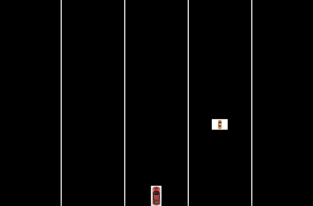
- Basic background
- Basic user car
- Basic lanes
- Controlling user car using keyboard left and right arrows
- Generate transparent cars
- Collision detection with transparent cars
When it comes to PyGame projects, reusable code is extremely
important. That's why we drew every surface using readable functions like draw_user_car() and
draw_background().
We called all these draw functions in the infinitely running main code.
#code snippet from game.py

running = True
while running:
    draw_background()
    draw_user()
    draw_lanes()
Modular code is also important for
reusability, so we defined constants in a separate file constants.py and imported it in our main
game file.
#code snippet from constants.py

USER_CAR_PATH = "images/user_car.png"
CPU_CAR_PATH = "imagines/cpu_car.png"

USER_CAR_CENTER = (600, 750)

LANE_COLOR = (255, 255, 255)
LANE_WIDTH = 4

LEFT_LANE_START_POS = (240, 0)
MIDDLE_LANE_START_POS = (240*2, 0)
RIGHT_LANE_START_POS = (240*3, 0)
AUXILIARY_START_POS = (240*4, 0)

LEFT_LANE_END_POS = (240, 800)
MIDDLE_LANE_END_POS = (240*2, 800)
RIGHT_LANE_END_POS = (240*3, 800)
AUXILIARY_END_POS = (240*4, 800)
Caching
Generating cars that all move implies keeping track of all car objects. A car needs to disappear after hitting the bottom boundary. To solve both of these problems, the dictionary data structure can be used. If a car exists in the dictionary, it implies that it's on the screen. Therefore, we will iterate through the dictionary to apply a move in-place to all cars. If a car in the dictionary passes the bottom boundary, then we will delete it from the dictionary.
Collision detection was very simple with
pygame.Rect.colliderect() that we learned to use in a previous lab. If a car runs into the user
car,
then we set the game state to GAME_STATE_OVER
- Phase 2: Features
Restart button
If a collision occurs between the user car and a computer
generated car,
the game state is set to GAME_STATE_OVER. This event should set the GUI to the restart button menu.
If you click anywhere on the restart button menu, the game restarts, resetting all global variables and setting
game state to GAME_STATE_RUNNING. Click detection was done by checking
event.type == pygame.MOUSEBUTTONUP and game_state == constants.GAME_STATE_TITLE in the event loop.
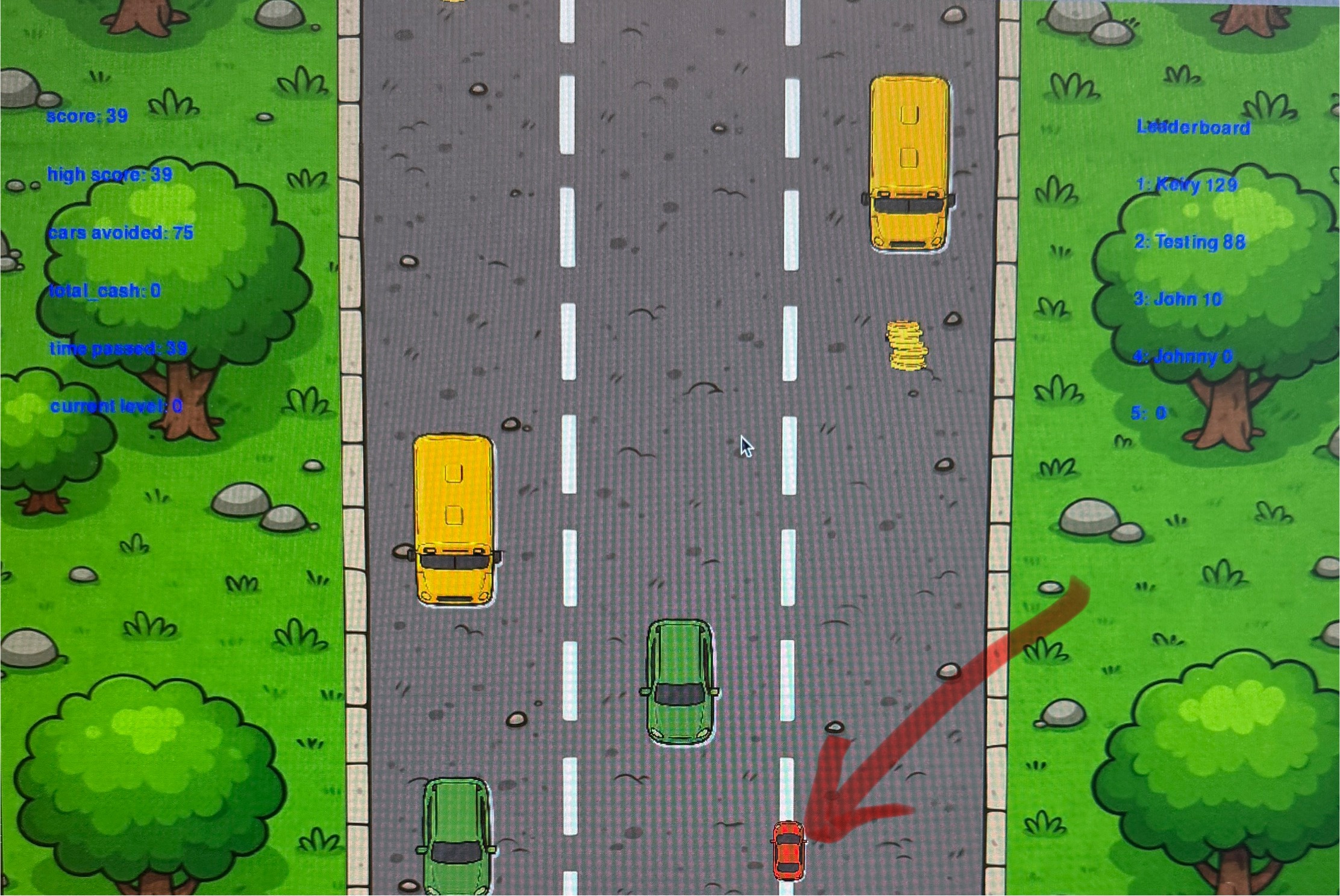
Statistics
To make the game feel more competitive, we introduced global
variables
score, high_score, cars_avoided, total_cash,
time_passed, and
current_level
-
score: calculated using the formula (time passed + total cash) -
high_score: updated during the game if score > previous high score -
cars_avoided: updated whenever a car passes the bottom boundary of the game -
total_cash: updated when the user car collides with any 3 forms of money: coin ($1), bill ($5), or stack ($10) -
time_passed: calculated using the formula (current time - program start time) -
current_level: updated by +1 every 60 seconds, synonymous with difficulty
#code snippet from game.py

def draw_statistics():
  draw_score() # draws both high score and score
  draw_cars_avoided()
  draw_total_cash()
  update_time_passed()
  draw_time_passed()
  draw_current_level()
Leaderboard
To make the game competitive, we included a leaderboard that
displays
the top 10 players according to score. We stored player and score information in a text file
player_scores.txt as a simple
database. Your entry (name, score) is only written to the database after the game ends. For efficiency, the file
is only read once, before the start of the main loop and stored in a list of tuples
(player_name, player_score) sorted by score. This way, we can efficiently draw the leaderboard by
iterating through the list.
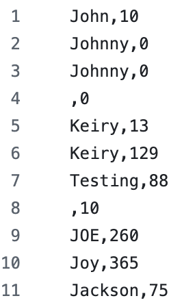
player_scores.txtTitle menu
The title menu is a requirement for every game. We added a game
state called
GAME_STATE_TITLE and similar to how we implemented the restart screen, we check in the event loop
if event.type == pygame.MOUSEBUTTONUP and game_state == constants.GAME_STATE_TITLE, then we set
game state to GAME_STATE_RUNNING.
It's a requirement for you to set your name in the title screen
so that your entry can be added to the database used in leaderboard creation. Writing the text input to the
screen
was done using PyGame's event module that can detect key presses, which we previously used for
keyboard
movement of the car.
#code snippet from game.py

def draw_input():
  user_input_text = font.render(user_input, True, WHITE)
  lcd.blit(user_input_text, constants.USER_INPUT_CENTER)

user_input = ""
player_name = ""
currently_writing = True
while running:
  if game_state == constants.GAME_STATE_TITLE:
    draw_title()
    draw_restart_button()
    draw_input()

    for event in pygame.event.get():
      if event.type == pygame.KEYDOWN and currently_writing:
        if event.key == pygame.K_RETURN:
          currently_writing = False
          player_name = user_input
          reset_game()
          game_state = constants.GAME_STATE_RUNNING
        elif event.key == pygame.K_BACKSPACE:
          user_input = user_input[:-1]
        else:
          user_input = user_input + event.unicode
Ramping difficulty
Since the objective of the game is to collect as much money and survive for as long as possible, difficulty should scale by distance traveled or time elapsed since the start of the program. Thus, the acceleration of the cars ramp up proportionally to time elapsed in seconds: acceleration = time elapsed * 0.1.
Every 30 seconds of playing time, the spawn probabilities of types of cars changes. The max difficulty of car generation starts at level 4, approximately 2 minutes of play time.
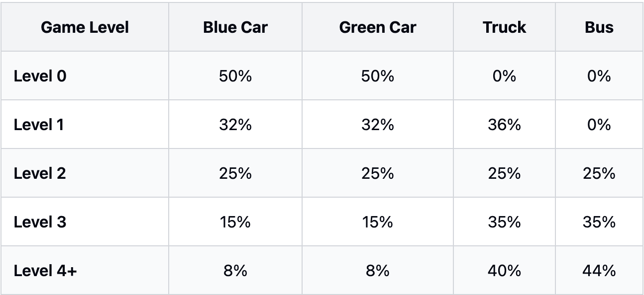
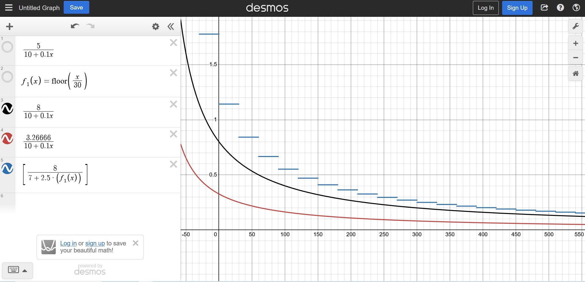
While designing the level system, we wanted to make sure that the game never progresses to generating impossible obstacles. That is, we wanted every collision to be caused solely from the fault of the player, not the game’s generation logic. The following graph shows the game's obstacle spawning timer that ensures this. The horizontal axis represents the game’s running time in seconds. The red plot shows the amount of time taken for the bus, the biggest obstacle in the game, to move downwards by its own height, thus clearing the spawn area. At t=0, this takes about 0.35 seconds. With increasing object velocity, this slowly decreases: at t=250, only about 0.1 seconds. The black plot shows the minimum time interval we target for spawning new vehicles. This is about double the time of the red plot, meaning that behind every obstacle we leave about a bus-length of space for the player to weave between. Finally, the blue plot shows the actual spawning interval for every level. This time interval approaches the black line, but never falls below it, ensuring that every obstacle generated by the game is possible if not for human reaction time.
Lives
This was a fairly simple mechanism to implement. Set
lives as a
global
variable that gets decremented by 1 with each collision. Since every frame the user car collides with the
computer-generated
car counts as a collision, we gave the user car an invincibility frame of 3 seconds after losing a life.
- Phase 3: Polishing and Performance Optimizations
PyGame Surface objects represent images. At this
point, our program was sluggish because of our mistake of failing to convert the Surface objects
into a format that is optimized for repeated calls of pygame.Surface.blit(), which draws the
image.
To optimize our image loading, we created all Surface objects in the global variables section and
applied
pygame.Surface.convert_alpha() to the objects.
Consistent performance is also important, so we capped the frame
rate
of the program to 60 FPS using my_clock.tick(FPS). This change also indirectly impacted the force
feedback of the motor, reducing force of oscillations.
Once all our game mechanisms and performance were acceptable, we moved onto improving assets. All of our assets were generated using ChatGPT's image generation model Dall-E 3. This includes the user car, blue car, green car, truck, bus, in-game background, title screen background, and title itself. The issue with ChatGPT's image generation model is that it can't generate images of specific resolutions, so we were unable to generate 1200 x 800 backgrounds. We instead generated the default 1024 x 1024 image and used Photo Resizer to transform into 1200 x 800 to fit our game. However, Dall-E 3 worked well with generating a png of various styles of cars, buses, and trucks which we cropped precisely for realistic collisions.
Our game uses a bird's eye view with assets moving relative to the car. This means that to the user car, computer-generated cars, money, and the background are moving past it. To simulate this, the background moves at half of the speed of the the computer-generated cars and money. We used two of the images of the same background and "connected" them. Once one passes the bottom boundary of the screen, it gets moved back to the top. This trick provides the illusion of an infinitely moving background as if you're really driving forward.
Hardware
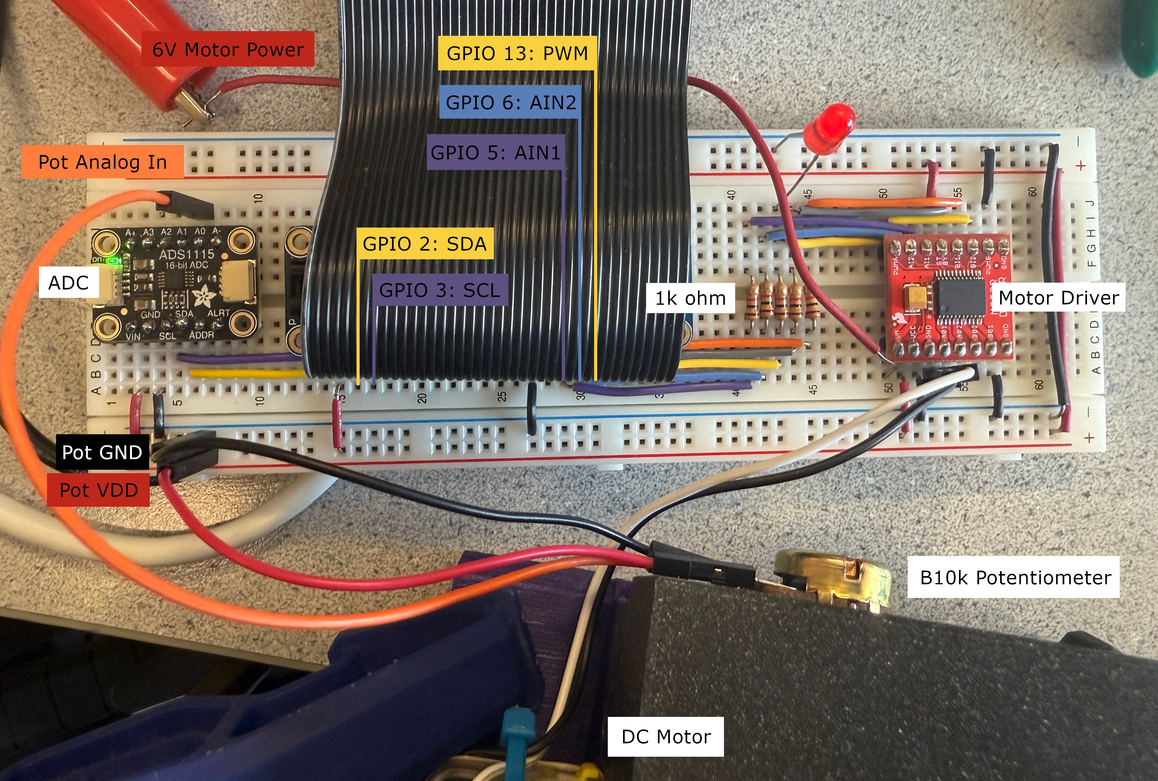
The hardware component of our project provides an input device to control the car within the video game. It is based on commercially available “force feedback” steering wheels commonly used on racing simulators and video games. To this end, we had 2 design goals for the hardware. Firstly, it must be capable of detecting steering inputs, and translating the input to a movement on-screen. Secondly, it must provide feedback back to the user based on the position and behavior of the wheel and/or the on-screen car.
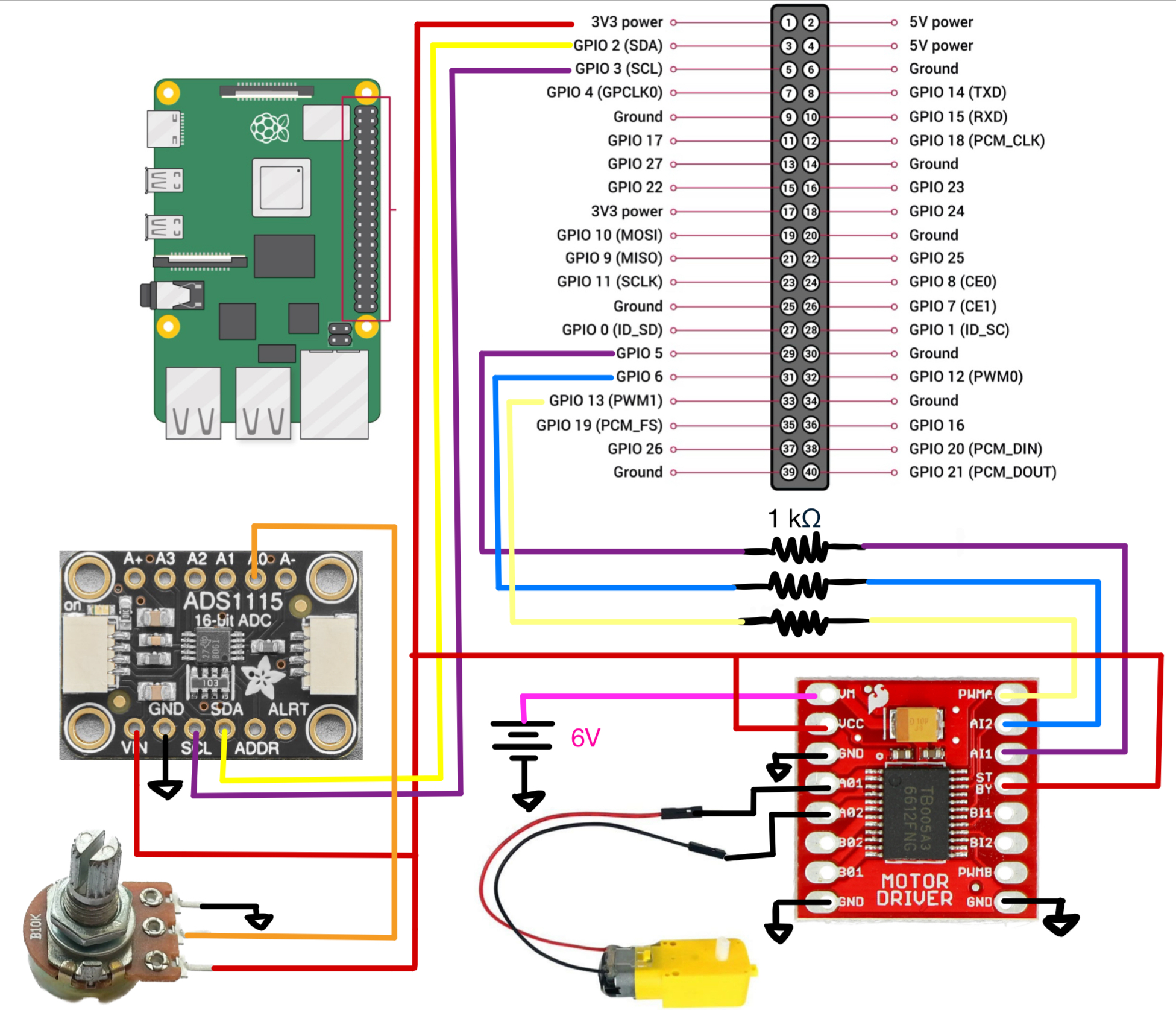
The steering inputs are read through a 10k linear potentiometer (adafruit ID: 562), which provides 300° of rotation. The analog voltage out from the potentiometer lies between 0V and 3.3V (VDD). This analog voltage is read through an ADC, specifically the 16-bit ADS1115 (adafruit ID: 1085). The TI ADC chip communicates with the RPi via I2C, and is capable of transmitting 860 samples per second. Our steering wheel program has a polling rate of 100 Hz, far below the maximum transfer speed of the ADC. In addition, the 16-bit precision is far more accurate than needed for a 300-degree rotation. This results in a 0.0046 degree resolution, far exceeding the tolerances of our physical components.
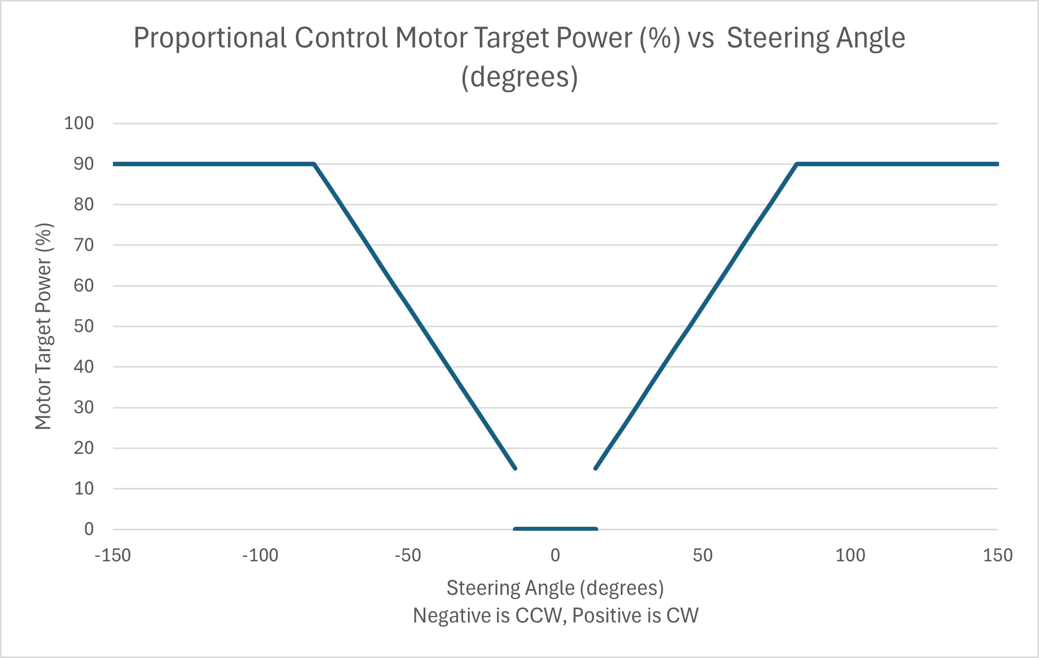
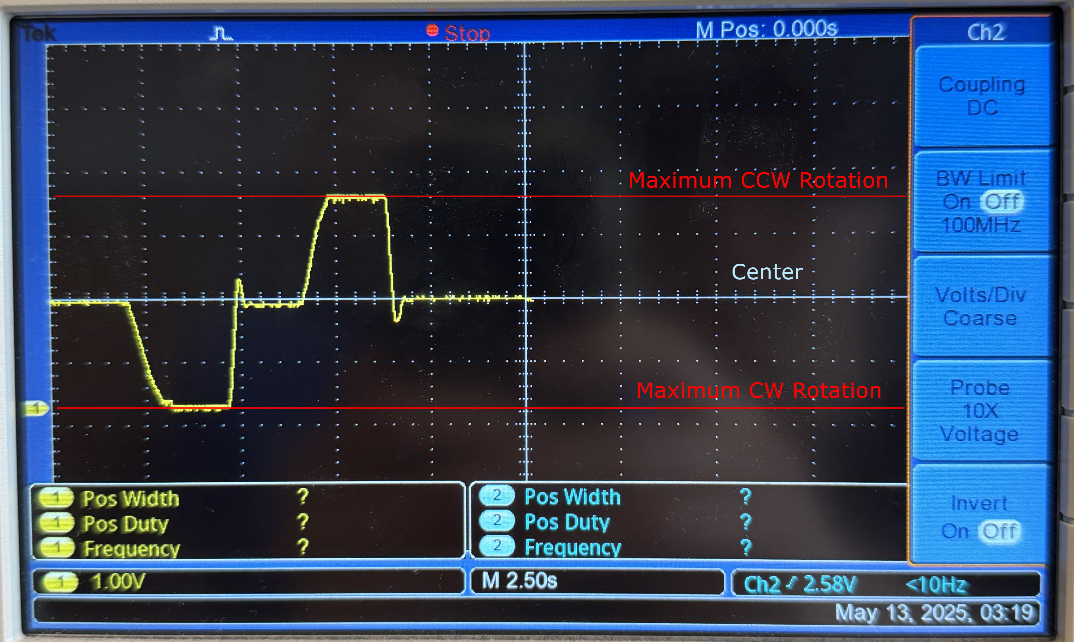
The steering feedback is provided through a DC motor that lies in the axis of rotation. The motor is a readily available “TT gearbox motor” commonly used on embedded projects (adafruit ID: 3777). The DC motor applies a restoring torque that is proportional to the rotational offset from center. The target DC motor power profile is shown below. There is a “deadzone” at the very center that helps to prevent oscillatory behavior. In addition, there is a slight derivative gain that also helps to tune out oscillations. Overall, this creates a closed-loop PD controlled device. The restoring torque provided by this motor is essential to creating an input device that simulates real-life driving dynamics. While this DC motor was used due to its wide availability, it had some downsides that limited other design parameters. We will suggest alternatives in the latter improvements section.
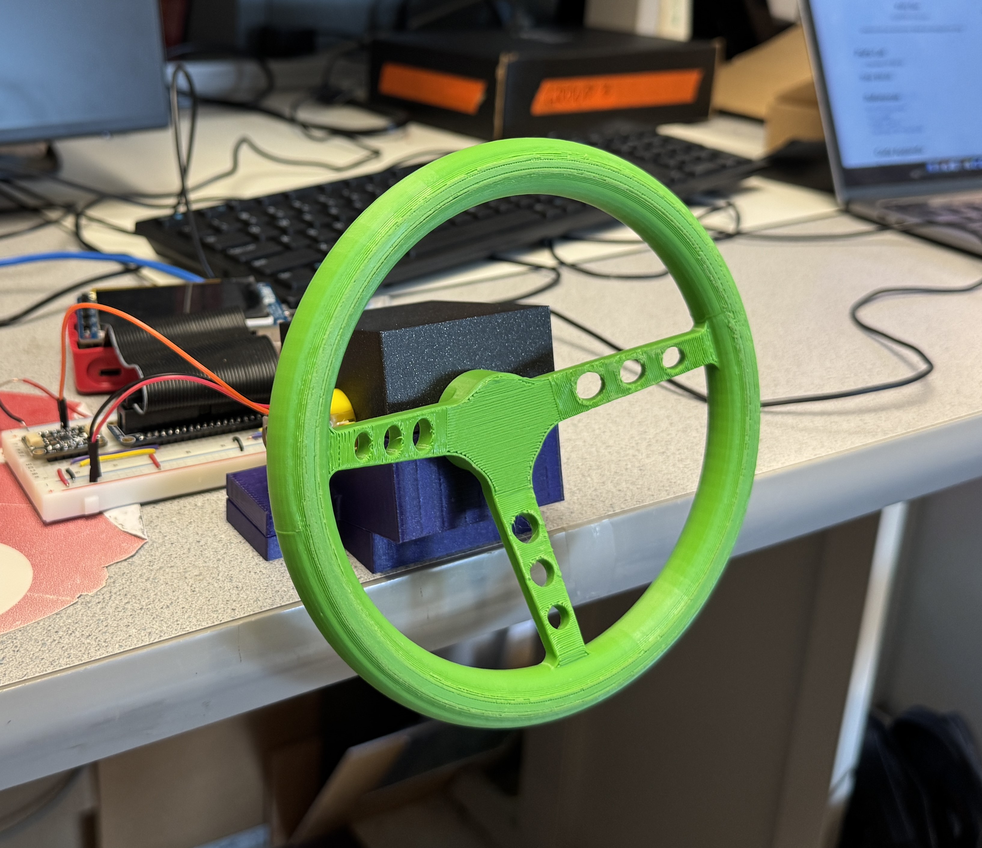
All other components, including the steering wheel, housing, and the angled base were 3D printed in PLA. The TT gearbox motor has two output shafts on opposite sides, but sharing the rotational axis. This allowed us to attach the steering wheel on one side, and the potentiometer on the other, with all three components sharing the steering axis. A short 3D printed piece connects the double D motor output shaft to the potentiometer. For the detailed assembly of the various components, please see the short video below.
Force Feedback Steering Wheel Assembly
Precise control of the DC motor is achieved through the SparkFun Dual TB6612FNG Motor Driver. This requires three GPIO pins of the RPi system: pins 5 and 6 connect to AIN1 and AIN2 respectively, and encode the on/off as well as the direction states of the DC motor. Pin 13 (PWM1 channel) is used to encode the motor speed through the duty cycle of the PWM signal. In combination with the two GPIO needed for the I2C bus, our design uses 5 GPIO pins in total.
Testing
Exploring force feedback and FIFO
When we were first incorporating force feedback, we tried a
complicated
method of running two scripts and using a FIFO for communication since that's what we learned in lectures and
lab. However, that didn't work out and we tried debugging by running the cat command on the FIFO,
and it showed
proper printing to the FIFO. Loose coupling was what we were going for when we had the idea of the FIFO, but we
decided
to simply incorporate the force feedback logic into our game code since we were on a time crunch.
Implementing keyboard movement
Although keyboard movement isn't directly related to our project, it was useful for debugging, isolation from hardware, and enables asynchronous workstyles. While one of us is working on features for the game, the other is testing the hardware components like the motor and potentiometer. Thus, it was a great productivity boost for our team.
OSError problems
We ran into two OSErrors while testing the game.
-
IOError: [Errno 5] Input/output error -
IOError: [Errno 121] Remote I/O error
After doing research on StackOverflow for solutions to these
errors,
we tried the fixes of playing around with the time.sleep() that's needed for reading from and
writing to the I2C. However, the errors still persisted. For some reason, after running our game script multiple
times makes the error go away temporarily. This still needs to be investigated.
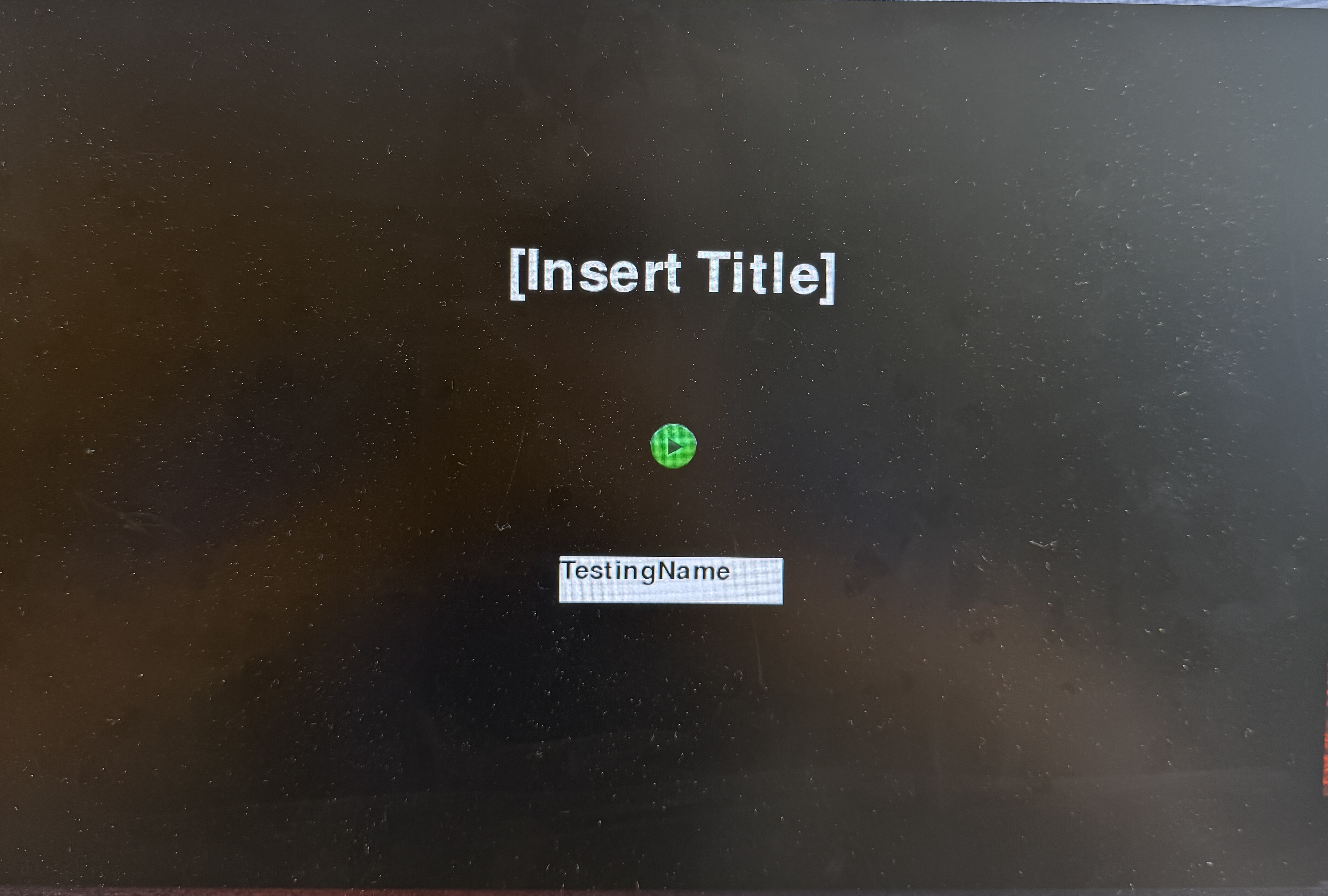
Fill-in text box
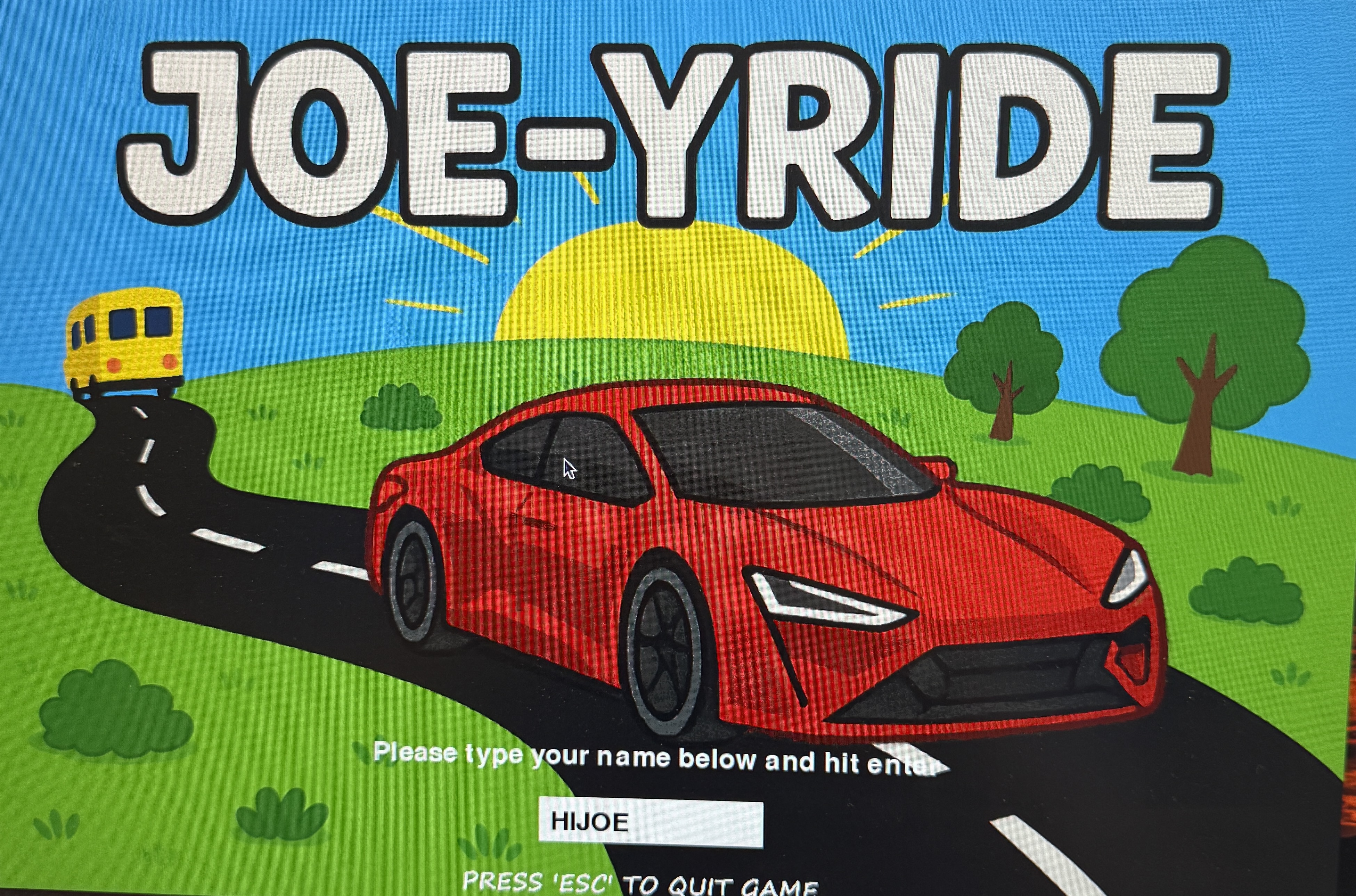
We started with a barebones title page with the essentials: a title, a start button, and a white box for typing in the player's username. As long as we had the logic working for starting the game from the title screen and typing letters into the textbox, that's all that mattered. From there, we were able to add art to polish it.
Statistics and leaderboard
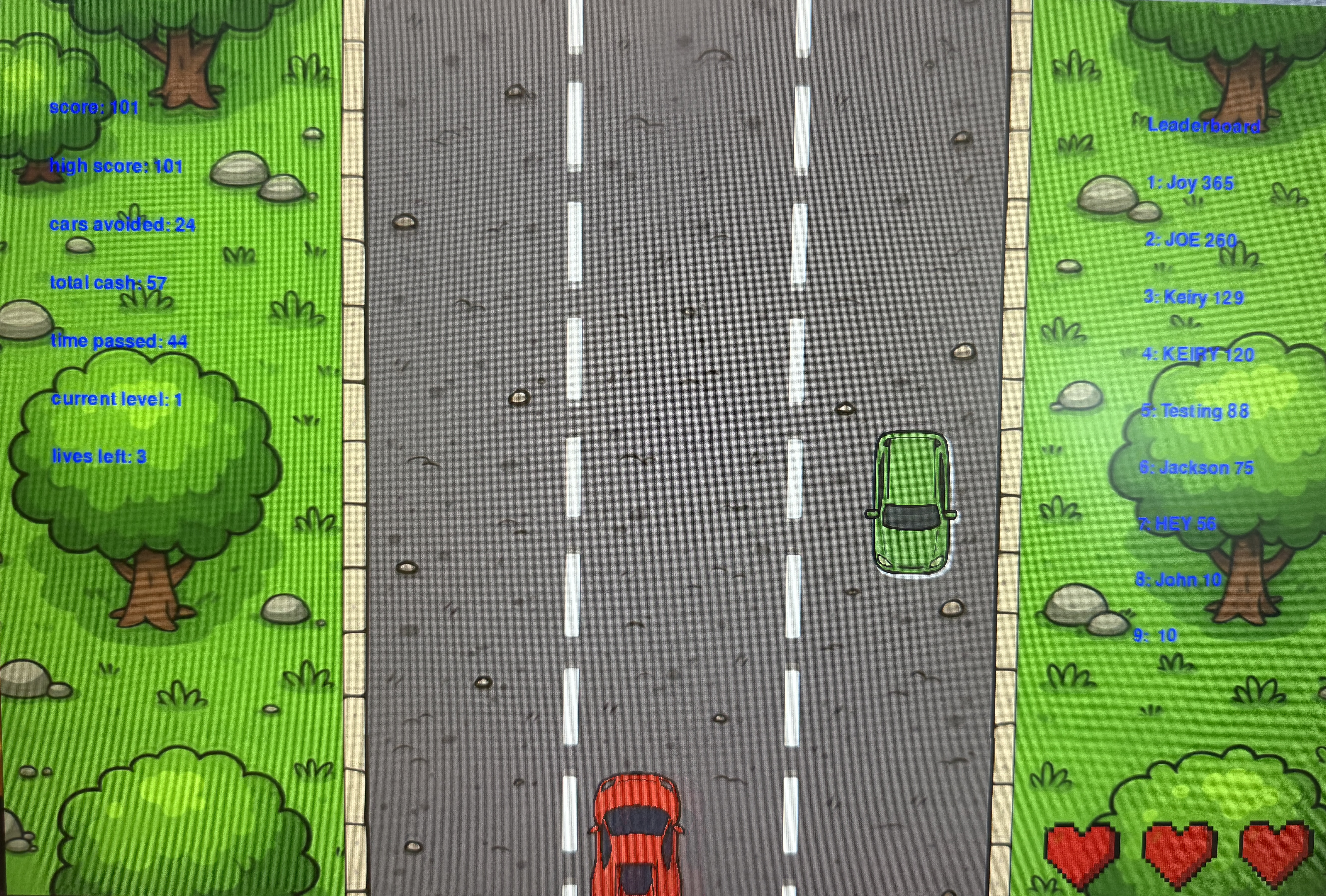
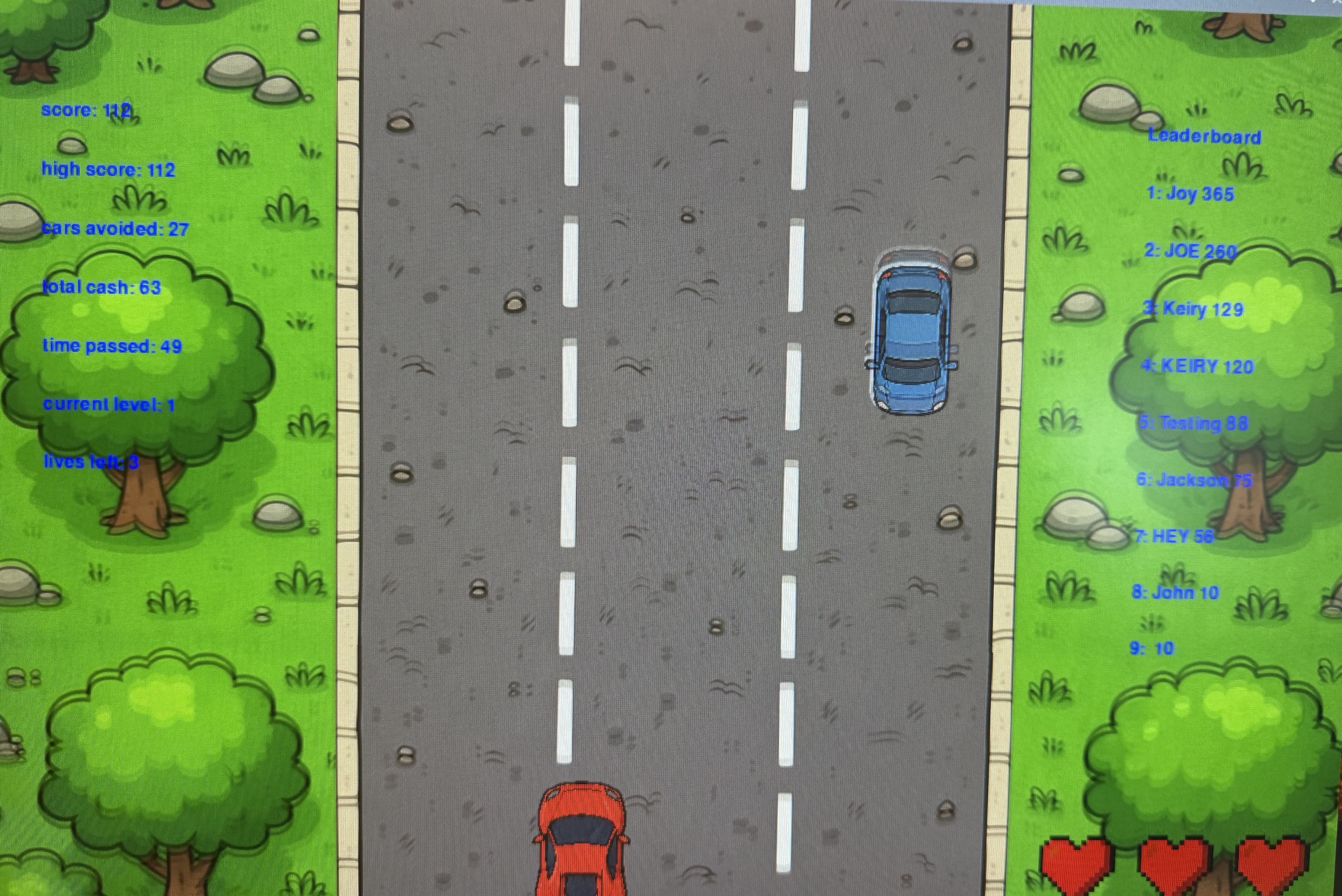
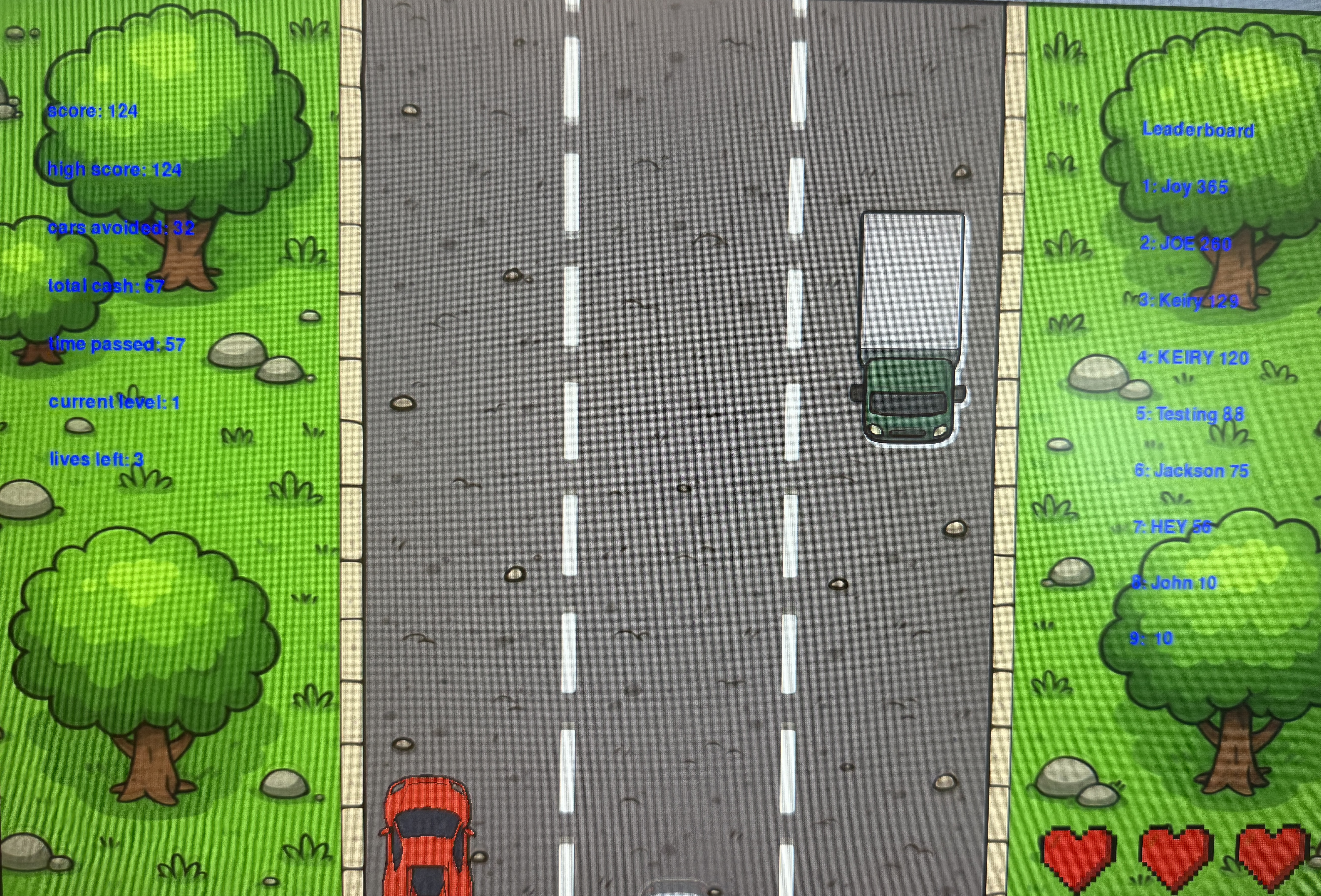
We intentionally scaled the size of the car by a factor of 0.2. This way, the statistics would continuously update since the car is too small to be hit by any computer-generated cars if it stays on the white lines. Since score is a function of time, we would intentionally get hit by a car upon reaching a score that beats the person on top of the leaderboard. The score update after the loss would give us a signal if the leaderboard mechanism and database are working correctly.
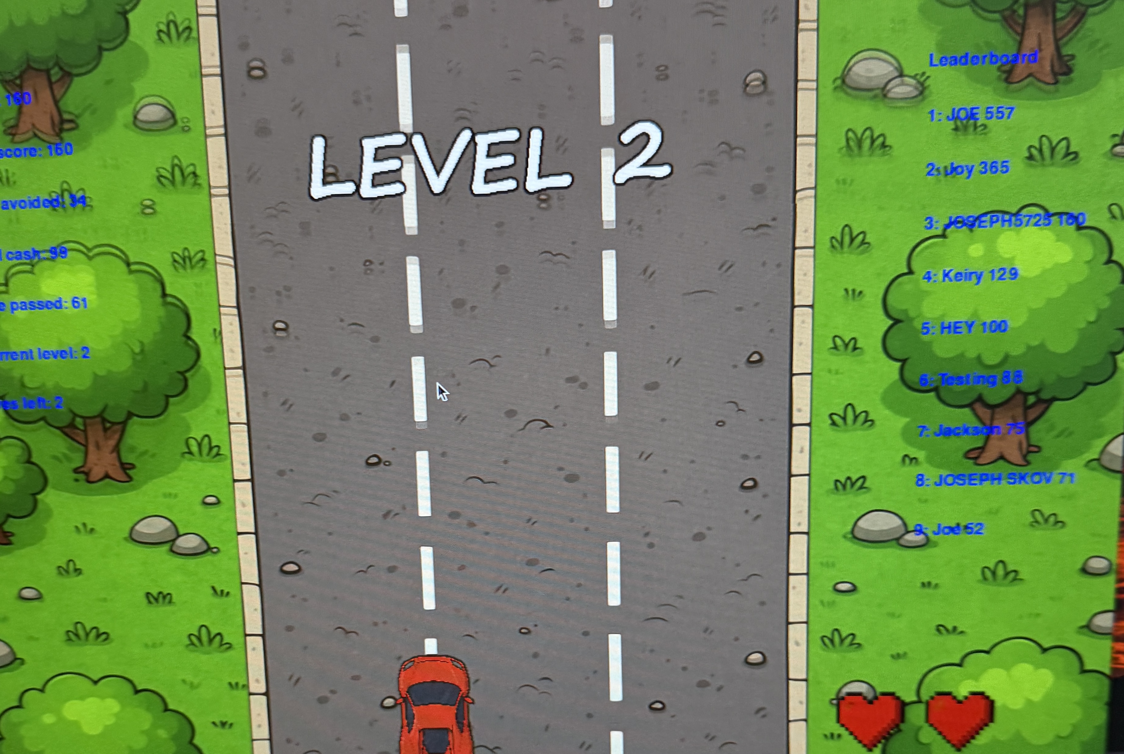
Level display + dropping lives
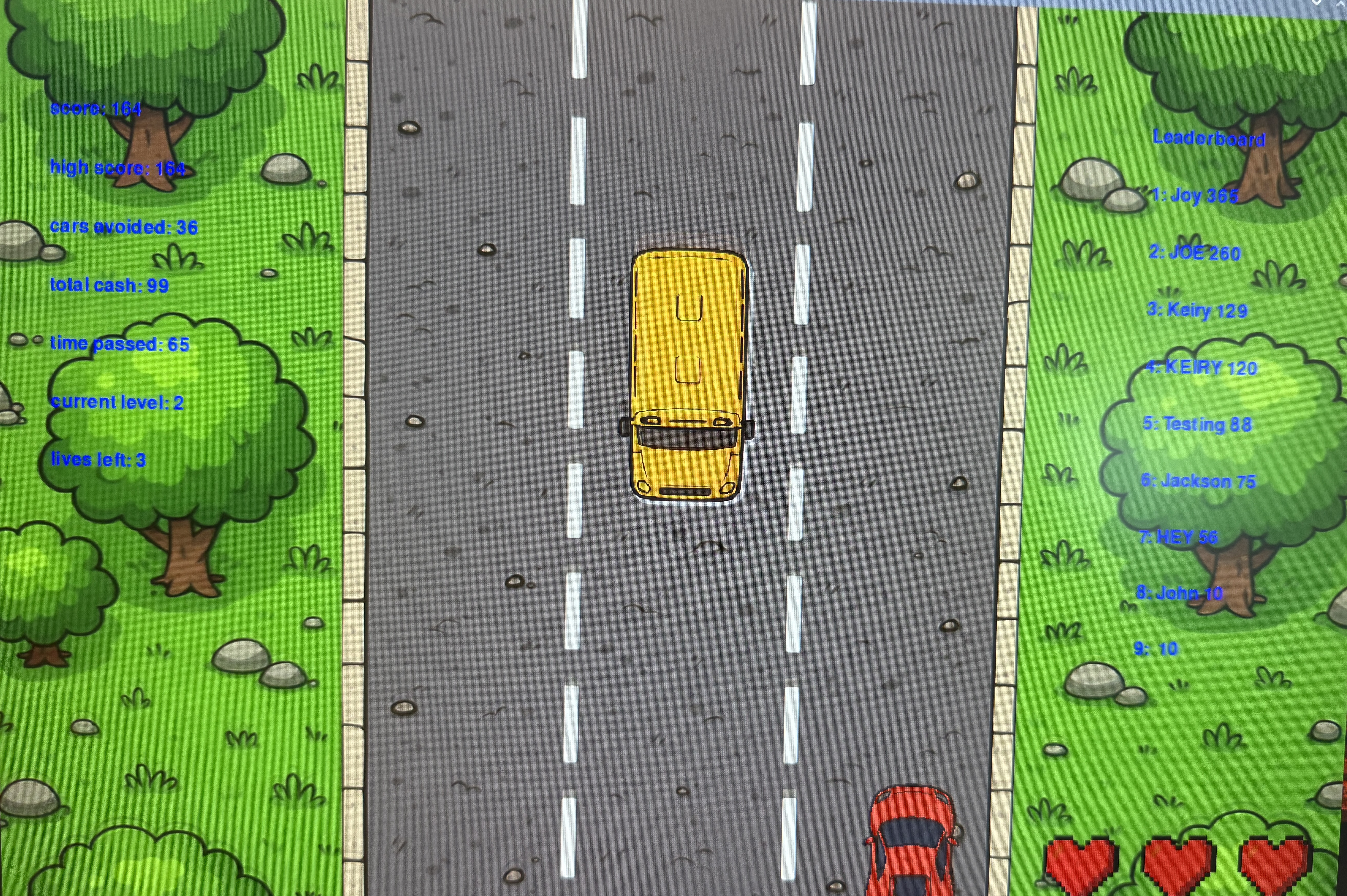
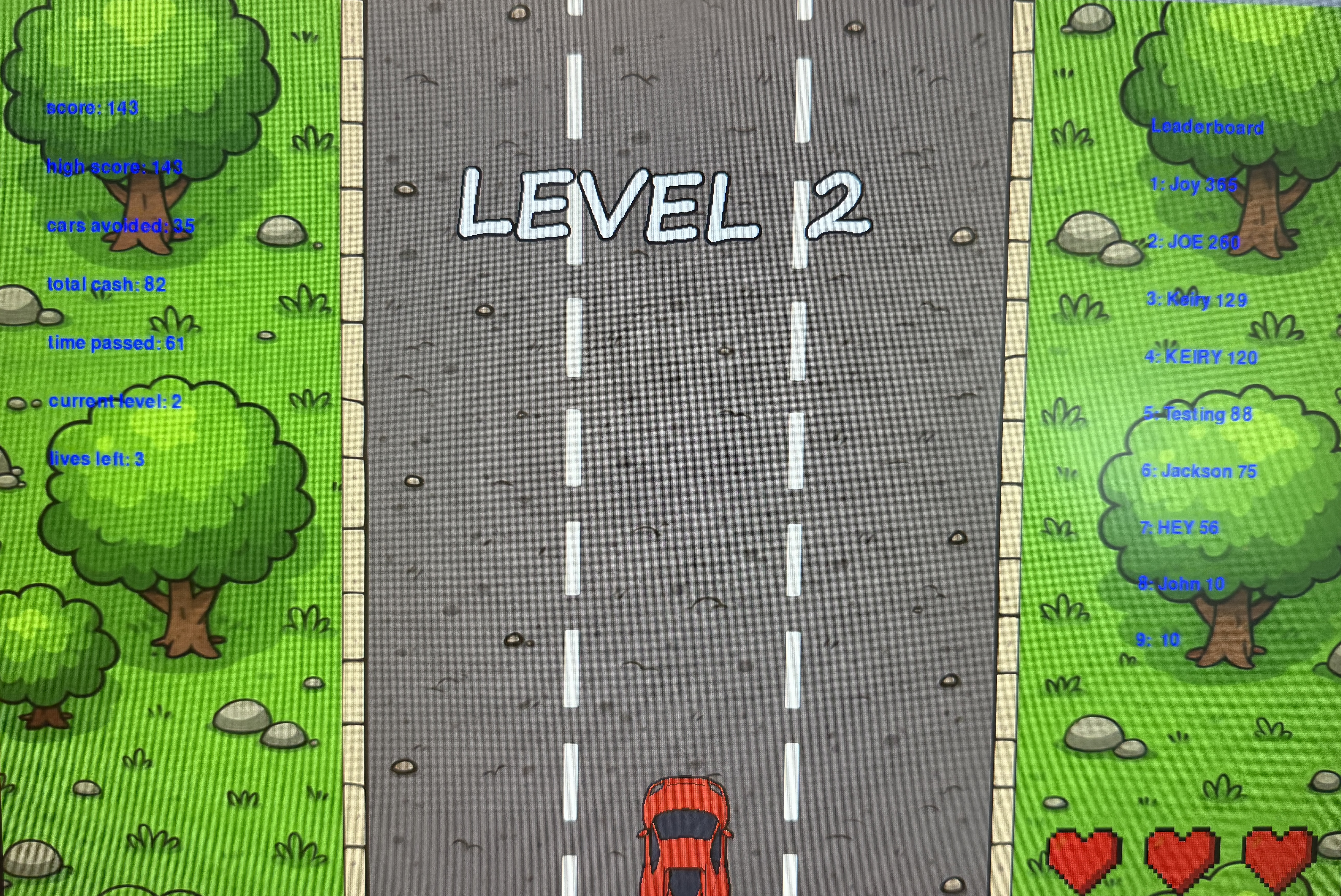
On the left side of the screen, we display statistics including the current level in the form of text. We also display the time elapsed. Our code increments current level by 1 every 30 seconds passed. Therefore, at level 2 (0-indexed), 1 minute has passed, and we verify by checking the current level and time passed statistics in blue text.
There's two steps to making sure we are dropping lives correctly.
- Verifying the invincibility frame is 3 seconds long
-
Verify the GUI representation of lives in hearts matches the global variable
lives
Preliminary Hardware Testing
Because the DC motor provides torque against the user’s input, we were concerned about potential issues within the gearbox of the motor. The opposing forces applied on either end of the plastic gear train could result in the teeth being stripped. The first feasibility test of our hardware was carried out through the motorManualControl.py program. This set the DC motor to a desired speed, after which we tried to physically stop the rotating wheel and even twist in the opposite direction. The gearbox survived this test without any stripping issues, proving the component suitable for our design. However, we did notice occasional clicks that we hypothesize to be the gearbox skipping due to the applied torque. The maximum output speed of the motor is clamped to 90% in our final design to prevent this issue. Furthermore, the final steering wheel has a larger diameter than the lab3 sourced wheels we used in this test. This results in a lower angular velocity under use that completely alleviated the gear skipping issues.
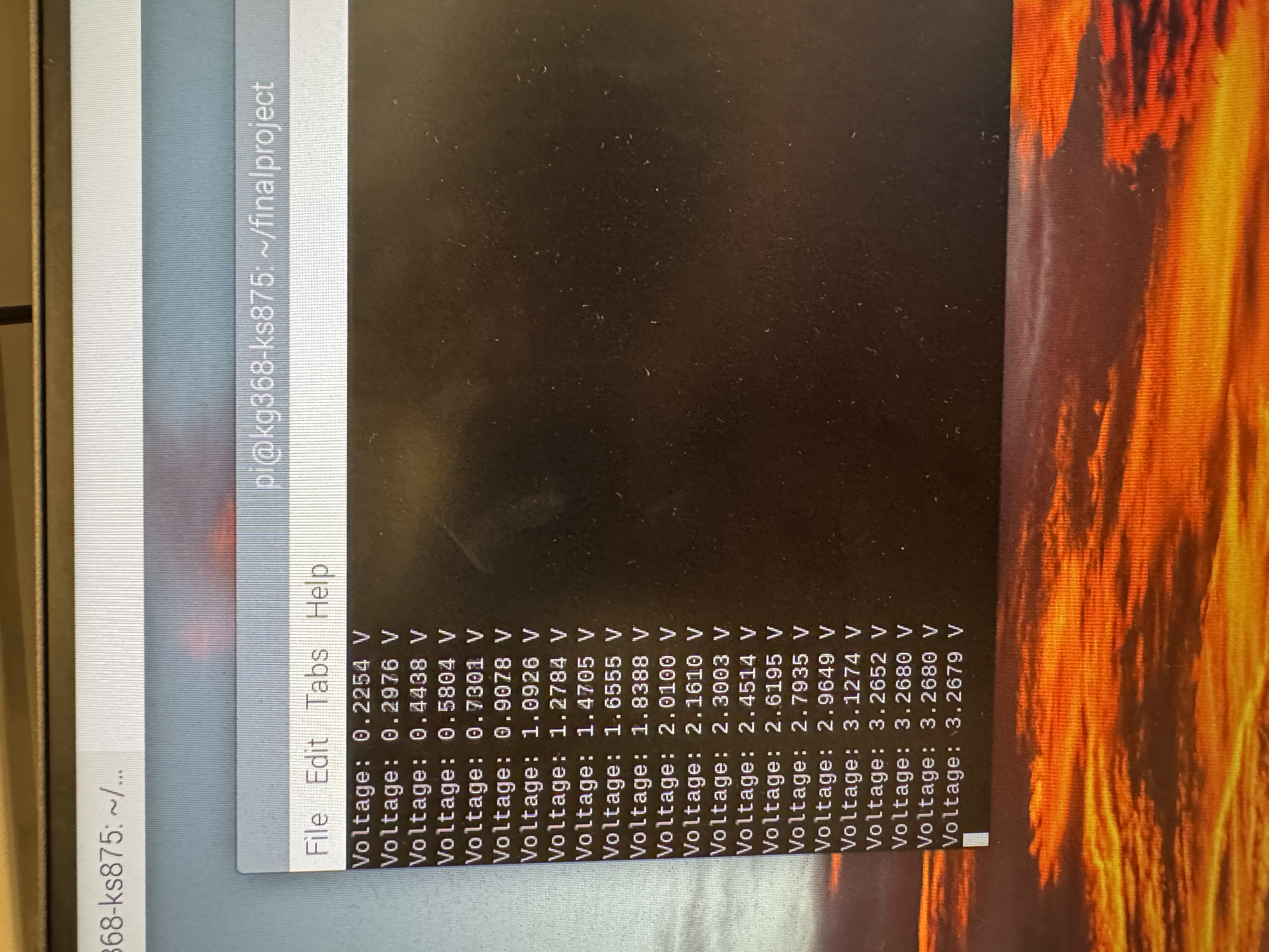
Potentiometer and ADC Integration
Next, the program ADC_read.py was written to test the potentiometer and ADC combination. This involved correct configuration of the I2C communication, including setting register values, I2C destination address, and correct scaling for our 3.3V VDD line. As mentioned above, we chose a polling rate of 100 Hz. With the potentiometer reading correctly, the two hardware components were ready to be combined together.
The resulting firmware is written in the forceFeedback.py program, which uses the potentiometer reading to set the DC motor direction and speed to return the wheel to center. At this point, the program was merged to a separate thread within our game.py program, where the analog voltage of the potentiometer also encodes the x-coordinate of the player vehicle.
Oscillation Tuning through PD Control
Since the potentiometer-motor system is a rotational equivalent to a mass-spring-damper system, we paid close attention to tune out any oscillations in the steering wheel. As mentioned previously, the center deadzone helps alleviate this oscillation. In addition, we use a derivative term to counteract the proportional gain. As shown below, the final system exhibits slightly underdamped behavior. However, through play testing, we found that this had no negative effect on the playability of the game.
Result
Polishing the title screen was much easier than getting the mechanisms we wanted working. We sketched the title page art and asked ChatGPT to fill it in for us and make it look cartoonish. ChatGPT performed well despite some scaling limitations with Dall-E 3. We also made a quick tweak to limit user name length to 11 characters so that the text fits inside the white box.
Levels are displayed on the top of the screen and there are a variety of cars generated.
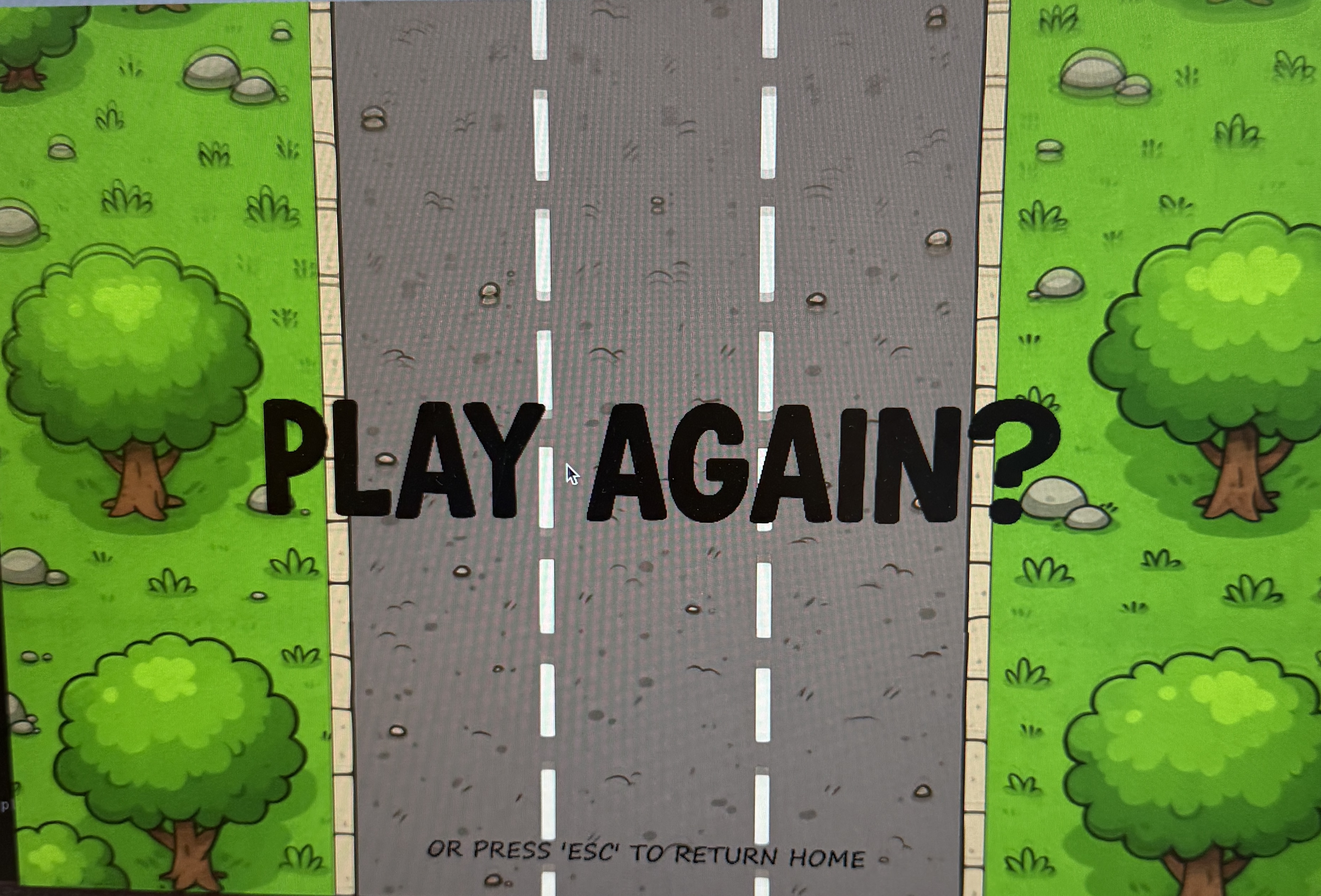
The game over screen still draws the moving background, which we kept because it felt like credits rolling after the completion of a game. If you click the screen, it should restart the game and reset all global variables except high score. If you press escape, it should bring you back to the title screen.
Future work
In a real arcade setting, these driving simulation games are multiplayer and you can race your friends if you both pay in arcade credits. We can take our project a step further in the future by adding support for multiplayer by having both players connect to a server. This is more of a dive into the software side, particularly game development.
Regarding improvements to the GUI, animations that can be made such as shrubs moving from the wind, smoke leaving the exhaust, and also different terrains as distance traveled increases.
The hardware components for this project were chosen partly due to their availability in the lab. For example, the DC motors are the same units from Professor Skovira’s lab 3. This particular motor has a few potential downsides. Firstly, as mentioned before, the plastic gears within the gearbox are not suitable for high stress applications such as this project. While we didn’t notice any stripping issues in our project, long-term reliability of the DC motor can be questioned.
Secondly, this DC motor is small, and has a correspondingly low power output. The consequence of our underpowered DC motor is the size of our steering wheel. Our 3D printed steering wheel has a diameter of 160mm, about less than half of the size of conventional steering wheels found in passenger cars. Ergonomically, it would be better to have a bigger wheel for our driving game. However, this would decrease the effective torque from the DC motor. The player would be able to easily overpower the motors, and the tactile feedback from the game would be greatly reduced.
Adafruit has a Bi-Metal Gearbox TT Motor (ID: 5857) that could address both of these issues. The use of metal in the gearbox makes it more resistant to stripping and would hold up better over long-term use. Secondly, the gear ratio is greatly increased from 1:48 to 1:90. Even using the same DC motor, this TT Gearbox would almost double the output torque at the steering wheel, allowing us to design a bigger steering wheel that is more comfortable and realistic. Best of all, these changes are completely internal to the gearbox, meaning the outer dimensions are identical to the part used in our design. Therefore, this should be an easy plug-and-play solution, and an option strongly recommended by us.
Alternatively, we would recommend recycling DC motors from broken electric scooters or “hoverboards”. The DC motor is a simple part that is unlikely to be the cause of malfunctioning devices. These motors would provide more than enough torque, likely matching or exceeding commercially available, top of the line simulator racing wheels.
Another hardware that could be swapped out for a marginal improvement is the ADC. Again we chose our component based on parts availability. While the ADS1115 chip proved perfectly functional in our use case, the 16-bit ADC chip is limited to a maximum read of 860 samples per second. Commercially available gaming peripherals such as mice and keyboards regularly exceed polling rates of 1000 Hz. In future iterations, we would want to match this polling rate, ensuring the most accurate input device for high-precision gaming. With the current 16-bit ADC, this would prove impossible. Adafruit has available a 12-bit alternative (ID: 1083) that supports up to 3300 samples/sec, more than capable of reaching the 1000Hz polling rate. Losing 4 bits of precision is inconsequential when reading 300 degrees of rotation, but the increased precision of high-speed inputs would be very important for the user.
Work Distribution
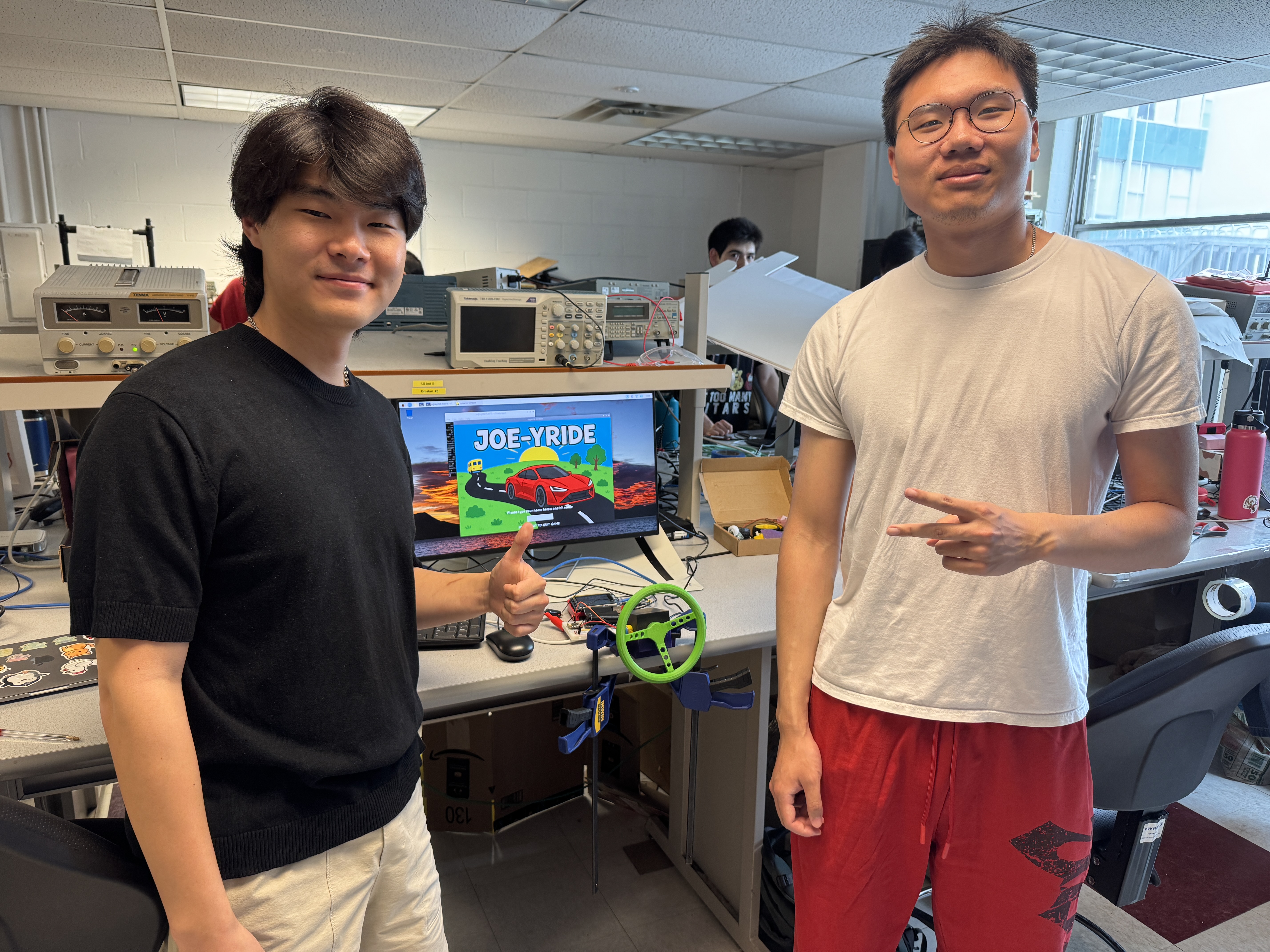
Project group picture

Keiry Gao
kg368@cornell.edu
Designed software architecture. Tested and debugged everything.

Andrew Shim
ks875@cornell.edu
Designed hardware architecture. Tested and debugged everything.
Parts List
- Raspberry Pi $35.00
- “TT Motor” DC Gearbox Motor (adafruit ID 3777) $2.95
- SparkFun Dual TB6612FNG Motor Driver $14.77
- B10k linear potentiometer (562) $0.95
- ADS1115 Analog-to-Digital Converter (1085) 14.95
Total: $68.62
References
R-Pi GPIO DocumentCrop Images
ChatGPT Dall-E 3
Title Screen Text Input Guide
ADS1115 datasheet
TT Gearbox DC Motor dimensions
B10k potentiometer datasheet
Code Appendix
The code for this project and stl files for the 3-D printed models have been uploaded to a GitHub repository