Nerf Turret
May 2024
David Schultz (dms489) & Erica Li (el549)
Our objective was to create an automatic Nerf blaster turret that would
The Nerf turret was built out of Legos and a Nerf blaster and was controlled using the Pi, a motor controller, Lego motors, and relays for the blaster control. Using a Pi Camera and computer vision (using OpenCV), the turret would scan the environment for a target (which we made a red circle). Two motors, one for horizontal motion and one for vertical, would aim the blaster so that the target would be in the middle of the turret's view. For height feedback to prevent the turret from continuing to try to move up or down once it has hit the range limit, two limit switches were used. Additionally, we displayed live video of the turret's view with targeting indicators to show when a target was detected. Once a target was detected and determined to be properly aimed at for 3 seconds, the Nerf turret would then be powered by the 5V pin from the Pi, through a relay, so that the blaster would then fire at the target. We also allowed for easy on/off control of the turret by touch on the PiTFT screen.
A frame turntable was built to hold and aim the blaster. This frame was built in two sections: a base, and a swiveling holder for the blaster. The base was heavily reinforced with frames and structural redundancy with rubber tires to support the weight of the batteries, motors, and Nerf blaster. It also provided a robust mounting surface for the swiveling base.

Base of the frame
The upper swiveling blaster base was a more complicated problem. It took a few iterations and help from a local Lego expert (13-year-old Matthew Schultz) to achieve the necessary structural integrity. To maintain unrestricted rotational movement, all electrical and other hardware including the blaster, Pi, batteries, and motors would be mounted on this rotating platform. The first step was to build the main structure to support the blaster. This brought the initial design problem: how to mount the blaster. The easiest method was to hang the blaster from above its center of gravity (upside down, so if we are looking at the blaster from a more conventional orientation, below). This supplied stability, but also allowed the mounting surface to be a block through the trigger.
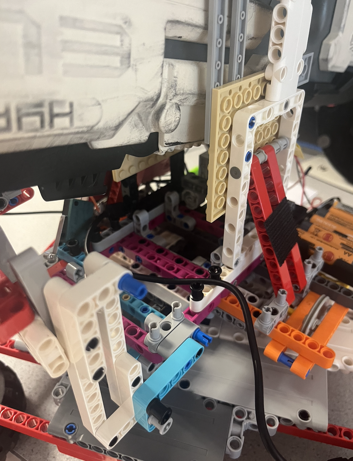
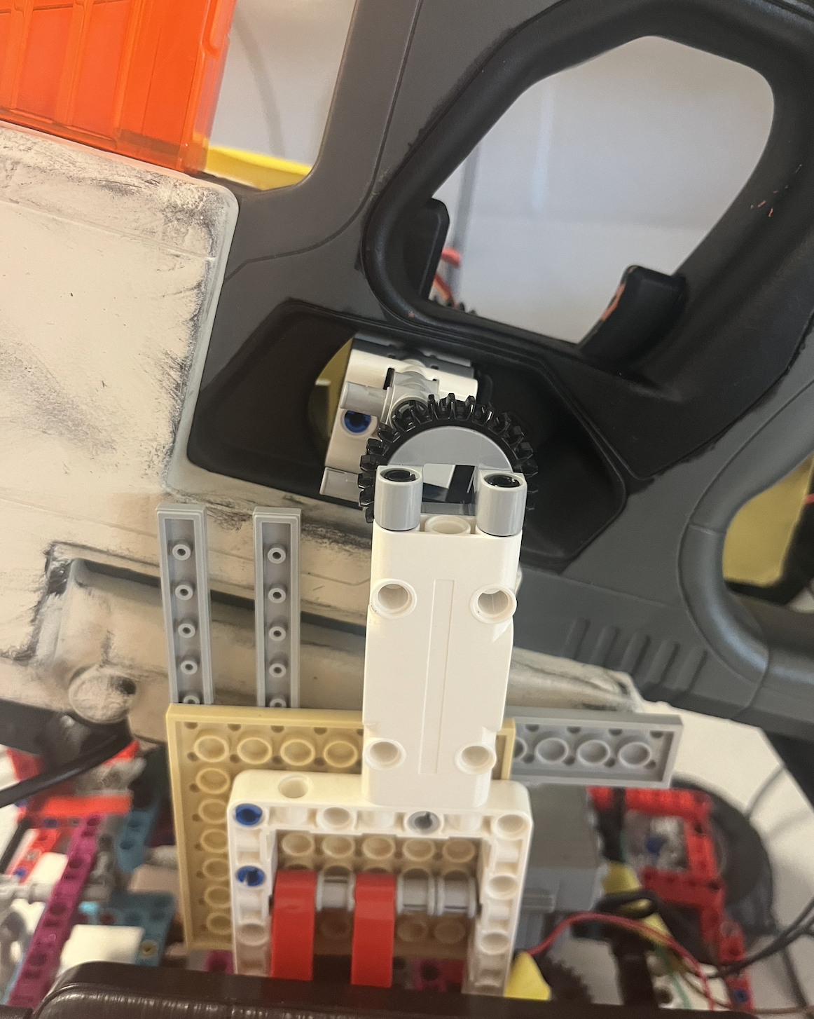
Blaster mounting
Next problem was how to get this platform to rotate. To achieve this the upper frame was built integrating a Lego turntable, along with an additional three wheels that interfaced with the base platform. The turntable provides the rotation and the wheels provide stability.

Rotational platform
Once these problems were solved, there was additional space left to mount the electrical systems, switches, and motor and gear trains to run the turntable and lift the blaster.
For the system, there are two degrees of freedom: horizontal and vertical angles of the blaster. There are two motors and geartrains for this purpose. For the horizontal rotation a simple geartrain is attached to the turntable. This geartrain is mounted on the upper frame and was connected to a standard 9V Lego power functions motor. This geartrain went through several iterations. Intermediate designs either broke (Lego chain), or did not have enough of a gear reduction to handle the large amount of inertia present in the system. Final gear reduction was 1:10.
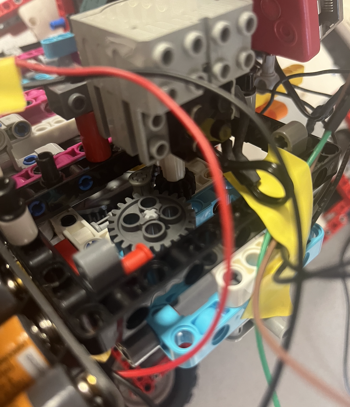
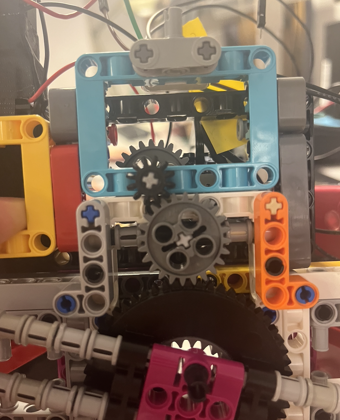
Lower gearchain
To handle the vertical aim adjustment, a lift mechanism was used attached to a Lego EV3 motor. A Lego standard lift element was used for this purpose, along with a geartrain to reduce the motor’s output.
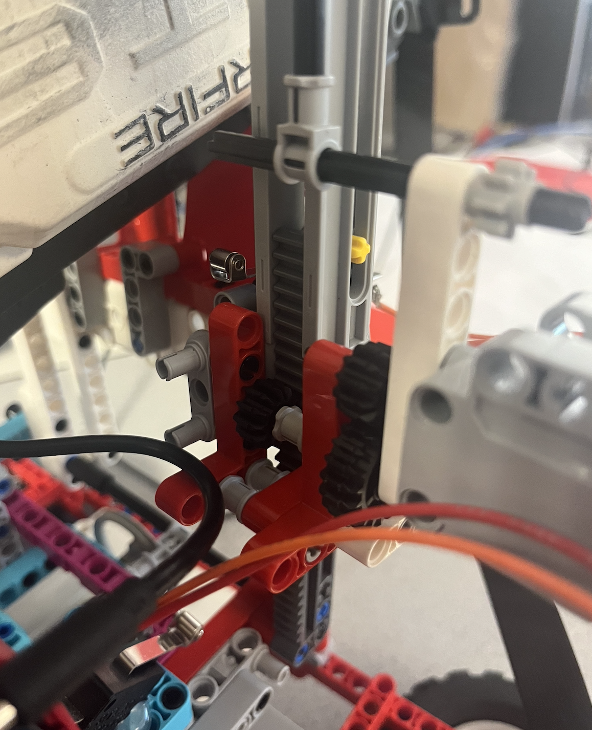
Vertical gearchain
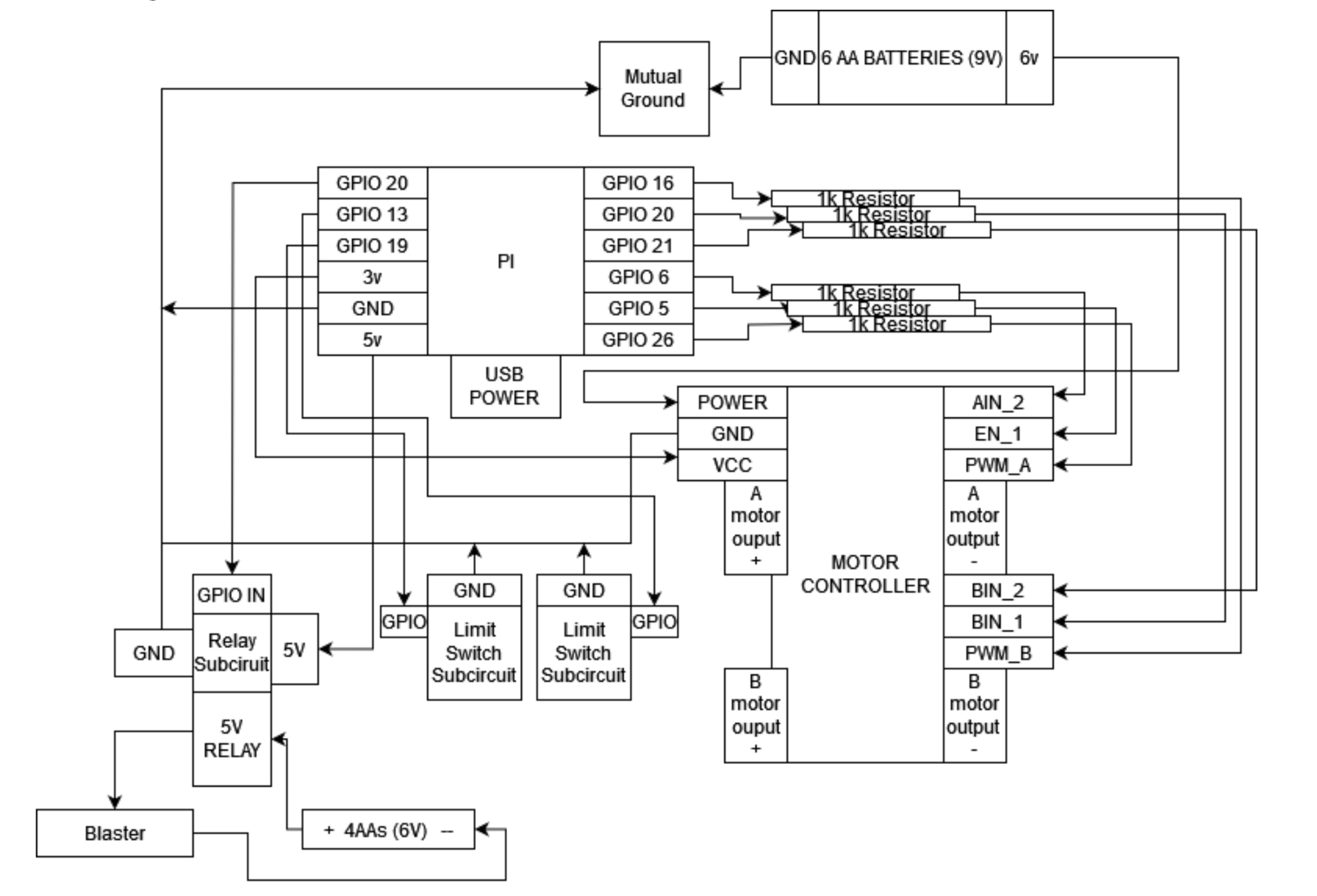
Main circuit diagram
Since our main structure was built out of Lego, it made sense to use Lego motors. We chose to use one EV3 Medium motor and one RCX motor. These motors can run on 9V DC power, so that is what we chose to use. To run these two motors we chose to use a motor controller that was provided to us for one of the in-class labs. This motor controller supports the use of two DC motors with PWM speed control for both, which was exactly what we needed. From there we hooked up power, motor power, and ground to the motor controller and picked free GPIO pins. For each of the motors, there are two control signals and one PWM signal. The PWM signal governs whether or not power is being sent to the motor, so a duty cycle can control the speed. The two control signals decide whether or not the motor is moving clockwise or counterclockwise or is off.
The motor power that was hooked to the motor controller was supplied by 6AA batteries which totaled 9V. The power for the motor controller was hooked up to the Pi’s 3V rail.
For our control system, we needed two limit switches for the vertical axis of the blaster’s range. These we hooked up using the guide given in class. In the larger diagram these subcircuits are indicated by “Limit Switch Subcircuit”

Switch circuit diagram
This diagram is lifted from the Lab 2 lab guide. We can see here that one resistor will limit the current flow so that we can protect the Pi GPIO when pressing a button. Without R2, the resistor between GPIO IN and group, a button press would cause the GPIO to be shorted and could damage it. The other resistor, R1, which is also much larger, ensures that only a small amount of current would be drawn when the switch is pressed and the other side is connected to 3.3V.
The blaster we chose for this project is fully electric. There are two main systems internal that facilitate the firing of the projectile. One for the flywheels that fire the projectiles, and one for the belt system that feeds the projectiles into the flywheels. There is a separate switch for both of these actions. This is a simplified version of looking at the system, as its internal circuitry has unnecessary safety measures that add complexity. All we needed to know was what switches to hook relays to ensure the blaster would fire. Initially, we assumed we would need two relays for each switch. But we realized that applying power to the flywheels and the belt separately was unnecessary as the blaster would fire just fine if power was applied to both simultaneously. Our plan became due to this simplification to simply bypass both switches and apply power to the battery terminals to operate the blaster.
The next project was to run a relay to allow power to flow to the relay. We will be examining here the “Relay Subcircuit” as seen in the larger diagram. We have a 5V relay, we needed to somehow turn it on with a 3V GPIO pin. To do this we run the 5V power on the Pi to run to the relay through a small BJT set by the GPIO pin. The diode between the BJT is used to suppress any high-voltage pulses that may occur when the transistor rapidly switches the power to the relay’s coil.
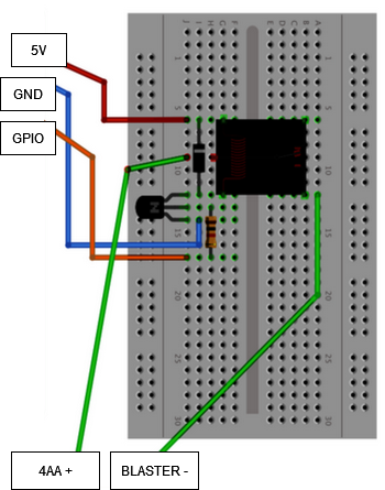
Relay circuit diagram (taken from RPi Cookbook)
This section of our project relies on the Raspberry Pi cookbook, including diagram and methodology.
Our camera for this project is a Pi Camera. It connects via a ribbon cable to the Pi’s motherboard. We ran into a few issues with bad wires, but once they were sorted we ran into another. Our operating system from lab 2, bullseye, was not compatible with the Pi Camera, so we did end up having to downgrade to a previous backup we had with the bookworm OS. Once that was solved it worked seamlessly with OpenCV.
The code for this system was contained completely in one loop. Within this loop, the pause logic is checked (including scanning the touch screen), the error is calculated through OpenCV, the motor speed is updated via PWM using the error value, and finally the OpenCV output is displayed on the TFT using pygame. To quit the game a callback function attached to a GPIO pin is used to kill the main loop and close pygame and the PiTFT.
To support the PiTFT and the pigame support for the PiTFT we had to include the two driver files (pigame.py and pitft_touchscreen.py) that were provided to us from the Lab 2 handout.
In order to pause the robot we chose to use tapping the screen as the mechanism. To do this we scan the TFT for a touch.

Our computer vision task was to identify a red circle in the image. There are a few stages to this: the first was color filtering, then object recognition, and then filtering. For the first stage a simple mask was created and applied:

The mask values were chosen through trial and error. Additionally, blur and an inversion were used to stabilize the detection. Next was to run the detection directly on the mask. The method of detection we wanted to use (Hough Circles) is based on edge detection and only easily supports one channel anyway, so running directly on the mask was the best choice.

The arguments chosen for the Hough Circles detection were chosen through trial and error and through specific planning. Param1 and param2, which are thresholding values, were chosen through trial and error. The other four parameters were chosen because we wanted to use the full resolution to detect smaller circles and to only pick one circle per screen without any regard about the size. Once these circles were detected, we looped over each output circle (almost always 1 or 0 given our arguments) and checked if the center is on a black (which indicated it was red) pixel to double check that the circle is in fact a real circle. If there is a valid circle, the x and y values are set for the controls section of the code, and the shooting control logic runs.
In this section we had to spend a significant amount of time tuning the arguments and thresholds for the computer vision section. There were many test days were the CV stopped working just because the lighting was different. We addressed this several times by further increasing the range of the color filtering. Additionally we didn’t initially limit our computer vision to only 1 possible target detection at a time (maxing out the minimum distance) and that led to many false positives and subcircles. As such, we were required to limit to 1 target on the screen.
When taking a look at our goals, we wanted to get the computer vision output on the PiTFT screen. When talking to TAs we found that this was not an area that was explored well, and solutions were not well known. To us, the simplest method seemed to be to try to use Pygame and the pigame PiTFT drivers to display the image on the TFT. We would be able to update the screen whenever we got a new frame as our framerate was reasonably high to create an interesting video to watch, allowing us to see what the blaster “sees” and perform testing more effectively. Our initial logic for pursuing this as a solution was that we knew that an OpenCV image/frame is simply a matrix, and an Pygame image should also be so.
Armed with this logic we were able to quickly find a Stack Overflow post that was able to create an Pygame image from an openCV image. Here is the line of code that we used to display our final image:

We did first however process our mask and add indicators for the circles on the screen. First to make it a three channel (color) image we did this:

After this was done if a circle was detected an indicator was added to the image:

There were two main control problems we had to figure out: one was the two-axis control, and the other was fire control. For two-axis control, the first thing we needed for our control system was reducing the error. To get an error value, we took the distance from the center of the screen to the center of the detected circle. The next thing we needed was to translate this error into an output for both the vertical and horizontal motors. Our initial attempts used pure proportional control for both the vertical and horizontal movement. This worked great for vertical control. We simply multiplied the vertical error by a constant and fed it into the duty cycle. The sign of the error determined the direction of the motor movement.
For horizontal control, due to the high level of inertia in the system as the system moved back and forth and the power needed to overcome static friction, a direct proportional control was not good. If the constant was too high the aiming would overshoot significantly and if it was too low the blaster could not make small adjustments due to the output not being high enough. Too address this we first tried PID control. Unfortunately when using PID the Ki and Kd caused heavy overshooting regardless of their magnitude without helping the small adjustment issue that much.
Our solution was to take the square root of the magnitude of the error times a constant, which worked perfectly. This method prevented the high error states causing overshooting and allowed low error states to still move the blaster. The below code is our final error calculation. When batteries degrade we can increase the multipliers, although new batteries would be the primary recommendation.

Our motors are controlled via a motor controller through PWM and two control signals for each motor. Along with the duty cycle calculations above, we take the direction of the error and apply the correct control signal (high and low alternating to switch directions). For the vertical lift we have limit switches that lock off a certain direction from the motors if they are pressed. For example if the top switch is pressed the motor cannot move up, regardless of the given error.
For the blaster we make sure the target is located in the center of the screen for 3 seconds, then fire for 0.7. We chose 75 pixels as the range. To accomplish this we set a time value if the circle is within the 75 pixels. As the main loop goes, if the circle is seen outside of that location the time value is set to maxint. If the value does not need to be reset for 3 seconds the blaster’s GPIO pin is toggled on and off with a 0.7 second delay. To measure the 3 seconds the time value is subtracted from the current time, and if it is three we fire. The time value is reset to max int after firing.
Our initial plan was as below:
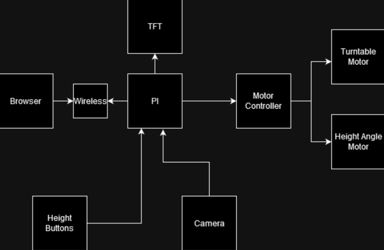
Early circuit diagram, from ~5 weeks ago
Between this initial plan and the final circuit diagram, we can see that we stuck fairly close to the plan -- the main differences were the additional components we needed to add to make sure the other parts worked as desired, such as the limit switches for the gearchains. We also didn't include where the blaster would be wired to in the initial plan as we weren't sure how to supply the blaster with enough power to fire at that point, but ultimately figured out how to do it with the Pi and a relay subcircuit, which we've included in our updated diagram as seen above.
Our hardware goals week by week were to 1) finish up the Lego stand design that David had started over spring break 2) wiring the motors to the Nerf gun, and 3) achieve control of the Lego motors through the motor controller & RPi. Our software goals were to 1) complete target acquisition through the camera and 2) to create control software that would effectively aim our turret at a target and display the camera’s view on the piTFT. Everything performed as planned as our team met these goals effectively and efficiently, even being ahead of our planned schedule by one week which allowed us to present at the Robotics Day event in Duffield.
Within the second week we tested the Lego motor functionality through the motor controllers and implemented the motor controller code and limit switches so that our swivel motor (aka side-by-side movement) and the vertical lift (aka up-and-down movement) were working properly. The toy blaster was also rewired to fire projectiles when power was applied to the battery terminals.
During the third week, we got the Pi Camera to start working and displaying on the monitor and used CV to detect a target, which we decided on being a red circle after debating the scope of the project we could tackle within 5 weeks with OpenCV. After a target is detected, we could see it outlined on the monitor display of the camera on the computer and the stand would rotate left and right to follow the said target, centering the target circle in the screen. We also redid some wiring and mounted the breadboard and camera to the Lego stand.
In the fourth week we got the vertical motor to track the target as well so our turret then would turn in all directions to follow the target detected on the camera. We also implemented a 5V relay so the Nerf gun would be supplied with the higher power it needed in order to shoot properly.
In the fifth week we played around with PID control and ways of regulating error correction while the gun was situated on top, as the additional mass led to more inertia that interfered with accurate aiming. We looked into the Lego gear ratios to try to fix this issue as well, which did help some. Ultimately, we found the solution in taking the square root of the error as aforementioned. With everything working perfectly while connected to power, we added batteries for the motors & Nerf gun and attached the battery pack for the RPi to the stand. We also edited crontab so the system would work on startup, and found our turret to be working perfectly.
Ultimately, we achieved creating an accurate tracking and firing system that is portable and entertaining to play around with. Users can experience being fired at when they hold up one of our pre-printed red circle signs, or even walk around the turret with a red shirt on (as our program does often detect non-circular large red objects as proper targets). Our project was also a hit at Robotics Day – we had many visitors stopping by, observing, and playing around with our turret (one person even mentioned that they overheard some professors saying that they had built something similar early in their ECE careers).
We experienced some difficulties with getting the camera display to work properly due to how delicate the hardware was, but once we got new hardware we were able to get the camera working smoothly using the guides from Canvas. The process of using CV to detect the color red & a circular shape was also a bit of a struggle but we ultimately were able to achieve what we wanted through a mixture of gleaning information from documentation on the Internet and trial and error.
We also were excited about the prospect of implementing our knowledge of PID controls from ECE 4760, a class we had both taken prior to this one, but found that PID would have actually worsened our error correction. We weren’t able to figure out why it made it worse in our case, but we “devised” a method of taking the square root of the error (while maintaining the sign of the original error) and multiplying it by some scalar to adjust for error based on the target’s proximity to the camera. We weren’t sure if this was a previously created control mechanism, but when we decided to test it out, we were pleasantly surprised to see that it solved all of our turret’s jittering issues and allowed for smooth movement and micro adjustments.
If we had more time to work on the project, we would've explored more complex target detection, perhaps with facial detection with an AI-trained model so we could shoot at people. We would also invest into a higher-quality camera in order to detect farther targets. To fire at these farther targets, we would also look into the physics of the bullets' projectile motion and adjust the aiming mechanism so that the Nerf bullets would hit the target.
Erica & David both worked on the software and hardware. David worked on the mechanical aspect of the system with the Legos (with the input of Matthew). Erica worked on the website & video editing.
Raspberry Pi Cookbook, 4th Edition by Simon Monk
Sparkfun Relay SPDT Sealed Part JZC-11F-05VDC–1Z Datasheet
5725 Lab 3 Handout for Motor Controller & PWM Information
5725 Canvas page: OpenCV Install; Install of pre-compiled Library - Fast!
Stack Overflow for CV Video display on PiTFT screen
	import cv2 as cv
	import numpy as np
	import RPi.GPIO as GPIO
	import sys
	import time
	import os
	import pygame,pigame
	from pygame.locals import *
	import math
	keep_going = True
	paused = False
	LEDPIN = 26
	AI1 = 5
	AI2 = 6
	dc = 0
	BI1 = 20
	BI2 = 21
	PWMB = 16
	RELAYPIN = 22
	os.putenv("SDL_VIDEODRIVER", "fbcon")
	os.putenv("SDL_FBDEV", "/dev/fb0")
	os.putenv('SDL_MOUSEDRV','dummy') # Environment variables for touchscreen
	os.putenv('SDL_MOUSEDEV','/dev/null')
	os.putenv('DISPLAY','')
	integral = 0
	prev_error = 0
	GPIO.setmode(GPIO.BCM)

	GPIO.setup(LEDPIN, GPIO.OUT)
	GPIO.setup(27,GPIO.IN, pull_up_down=GPIO.PUD_UP)
	GPIO.setup(AI1, GPIO.OUT)
	GPIO.setup(AI2, GPIO.OUT)
	GPIO.setup(BI1, GPIO.OUT)
	GPIO.setup(BI2, GPIO.OUT)
	GPIO.setup(PWMB, GPIO.OUT)
	GPIO.setup(19,GPIO.IN, pull_up_down=GPIO.PUD_UP)
	GPIO.setup(13,GPIO.IN, pull_up_down=GPIO.PUD_UP)
	Kp = 24/75
	Ki = 0
	Kd = 0
	p = GPIO.PWM(LEDPIN, 20)
	pb = GPIO.PWM(PWMB, 20)
	p.start(dc)
	pb.start(dc)
	pygame.init()

	pitft = pigame.PiTft()
	GPIO.setup(RELAYPIN, GPIO.OUT)
	pygame.mouse.set_visible(False)
	screen = pygame.display.set_mode((320,240))
	def callback_27(channel):
	    global keep_going
	    global pitft
	    print("Button 27 has been pressed")
	    pygame.quit()
	    del(pitft)
	    keep_going = False

	GPIO.add_event_detect(27, GPIO.FALLING,callback=callback_27, bouncetime=300)

	capture = cv.VideoCapture(0)
	x1, y1 = 0,0
	start_time = time.time()
	time_centered = sys.maxsize


	while(keep_going):
		pitft.update()
		for event in pygame.event.get():
			if(event.type is MOUSEBUTTONDOWN):
				x,y = pygame.mouse.get_pos()
				paused = not paused
		if(paused):
			GPIO.output(BI1, GPIO.LOW)
			GPIO.output(BI2, GPIO.LOW)
			GPIO.output(AI1, GPIO.LOW)
			GPIO.output(AI2, GPIO.LOW)
			continue
		isTrue, frame = capture.read()
		lower_red = np.array([155,185,0])
		upper_red = np.array([184,255,255])
		hsv = cv.cvtColor(frame, cv.COLOR_BGR2HSV)
		mask = cv.blur(255- cv.inRange(hsv,lower_red,upper_red),(10,10))

		circles = cv.HoughCircles(mask, cv.HOUGH_GRADIENT, dp=1,minDist = 1000 ,param1 = 50,param2 = 30, minRadius=0,maxRadius = 200)
		output = cv.merge([mask.copy(),mask.copy(),mask.copy()])
		if circles is not None:
			circles = np.round(circles[0, :]).astype("int")

			for (x, y, r) in circles:
				#print(mask[x,y])
				try:

				 if(mask[y,x] > 150):
				  continue
					#continue
				except:
				 continue
				x1= x-320
				y1 = y - 240
				cv.circle(output, (x, y), r, (0, 255, 0), 4)
				cv.rectangle(output, (x - 5, y - 5), (x + 5, y + 5), (0, 128, 255), -1)
				if(abs(x1) < 75 and abs(y1) < 75):
					if(time_centered == sys.maxsize):
						time_centered = time.time()
					else:
						if(time.time() - time_centered > 3):
							print("fire")
							GPIO.output(RELAYPIN, GPIO.HIGH)
							time.sleep(0.7)
							GPIO.output(RELAYPIN, GPIO.LOW)
							time_centered = time.time()
				else:
					time_centered = sys.maxsize

				#break
		else:
			#time_centered = sys.maxsize
			x1 = 0
			y1 = 0
		if(y1 < 0):
			if(GPIO.input(19) != GPIO.LOW):
				GPIO.output(BI1, GPIO.LOW)
				GPIO.output(BI2, GPIO.HIGH)
			else:
				GPIO.output(BI1, GPIO.LOW)
				GPIO.output(BI2, GPIO.LOW)
		elif(y1 > 0):
			if(GPIO.input(13) != GPIO.LOW):
				GPIO.output(BI1, GPIO.HIGH)
				GPIO.output(BI2, GPIO.LOW)
			else:
				GPIO.output(BI1, GPIO.LOW)
				GPIO.output(BI2, GPIO.LOW)
		else:
			GPIO.output(BI1, GPIO.LOW)
			GPIO.output(BI2, GPIO.LOW)
		error = x1
		integral += error
		derivative = error - prev_error
		out = 5*np.sign(error)*math.sqrt(abs(error)) #+ Ki * integral + Kd * derivative
		error = prev_error
		if(out > 0):
			GPIO.output(AI1, GPIO.LOW)
			GPIO.output(AI2, GPIO.HIGH)
			pass
		else:
			GPIO.output(AI1, GPIO.HIGH)
			GPIO.output(AI2, GPIO.LOW)
			pass
		p.ChangeDutyCycle(min(abs(out), 99))
		pb.ChangeDutyCycle(min(35* abs(y1)/50, 99))
		output_tft = cv.resize(output, (320,240))
		image = pygame.image.frombuffer(output_tft.tostring(),output_tft.shape[1::-1],"RGB")
		if(keep_going):
			screen.blit(image , (0,0))
			pygame.display.flip()
		cv.waitKey(10)
	pygame.quit()
	del(pitft)
	p.ChangeDutyCycle(0)
	pb.ChangeDutyCycle(0)