TidyPlotter
A Robust Drawing Machine
By Deemo Chen(yc938), Sabian Grier(srg293) - 2023/5/15
Demonstration Video
Introduction
The SCARRA Plotter is a 2-D plotter that utilizes a robotic arm design to reproduce images in jpeg or png format. It can be attached to most flat surfaces and can draw with various writing utensils. Both arms were 3-D printed using a resin printer and rotated using two stepper motors. It is important to note that a resin 3-D printer is not necessary to produce this design; it is just what we had access to. Additionally, we use a small servo motor to lift and drop the writing instrument.
Project Objective:
A 2-D plotter is far from a novel idea. Nevertheless, we chose to pursue this project to explore how cheap and accessible technology can be utilized to design and build a device capable of producing high-quality and accurate drawings. Unfortunately, many plotter designs are both large and expensive. Therefore, we aimed to create something robust, functional, and reliable in our development. Simultaneously, we also wanted to construct it using materials that could be cheaply bought or easily built by a large community of makers.
Design and Testing
Hardware Design
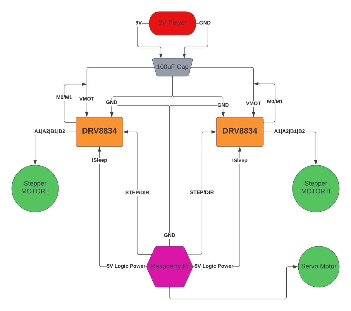
Fig.1 Hardware Block Diagram
Our hardware design's primary goal was successfully controlling two stepper motors and a servo. Our circuit was constructed in a way that was similar to the suggested design for A DRV8834 low-voltage motor controller(Fig.2). As can see from Fig.1, when supplying power to the two stepper motors, the labeled voltage is much smaller than 9V, but according to the motor specifications, this is only limited by the load current. Since there is a current limiting feature on the DRV8834 board, we were able to adjust it using the potentiometer. As we were powering the board and the motor, we could measure the voltage at the VREF pin and calculate the current being drawn by the motor using the equation I_motor = 2 * VREF. To help with mitigating the voltage spikes, we added a 100uF capacitor between the driver board and the power supply to ensure smoother motor operation and rotation. The board also enabled us to adjust the step granularity of the motors. With these motors, higher precision results in lower torque, and through experimentation, we found that our motors were still able to move successfully at 1/16 precision, meaning 3200 steps per rotation. This is achieved by hardware by pulling the M0 and M1 pins high.
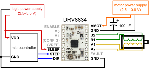
Fig.2 DRV8834 Reference Circuit
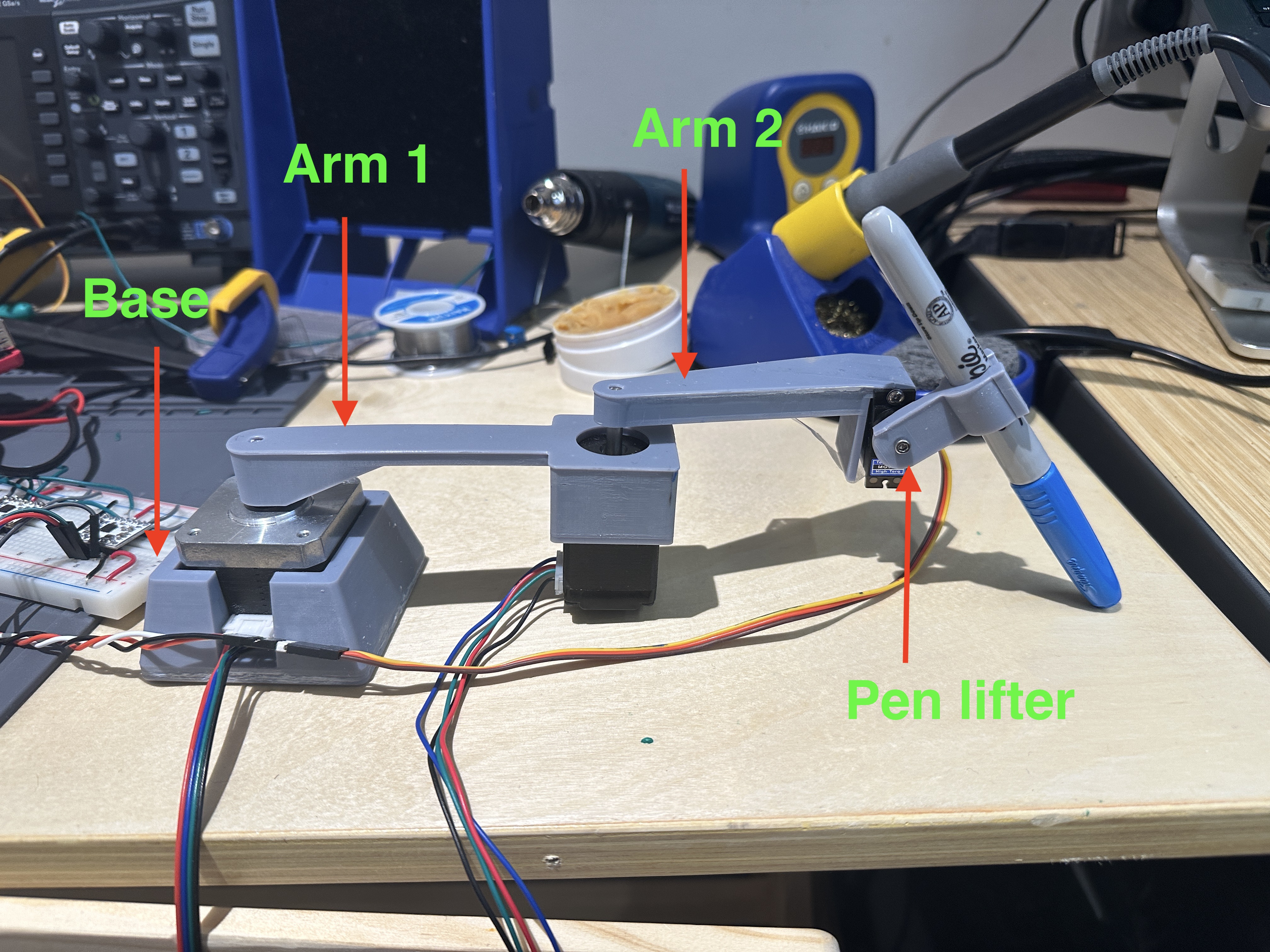
Fig.3 Plotter Components
For the mechanical component, we intended to provide those interested in owning or building a drawing machine with a design that is easy to replicate. This will enable those interested in using our CAD designs to forgo some of the challenges of creating their own. Our first 3-D modeled part is the base. This is used to support the first stepper motor. Additionally, we have two arms with a length of 10cm and a pen lifting mechanism connected to the servo motor(Fig.3).
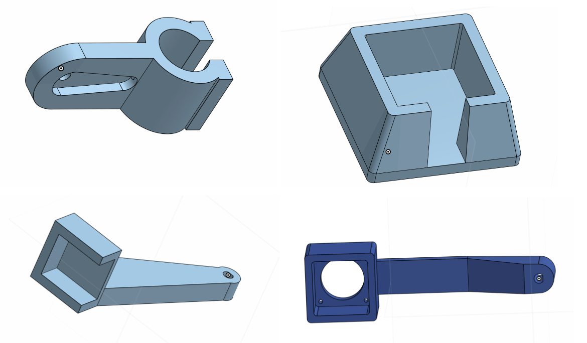
Fig.4 Parts Model
In developing these parts, we went through multiple iterations to create better fitment, more stability, stronger arms, and to accommodate different motors(Fig.4). These parts were printed using a resin 3-D printer to create an accurate and high-resolution part.
In this process, we ended up with several unused designs, such as a support for the second stepper motor and an arm 2 design which makes the pen drop vertically(Fig.5).
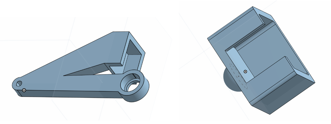
Fig.5 Extra Parts
Software Design
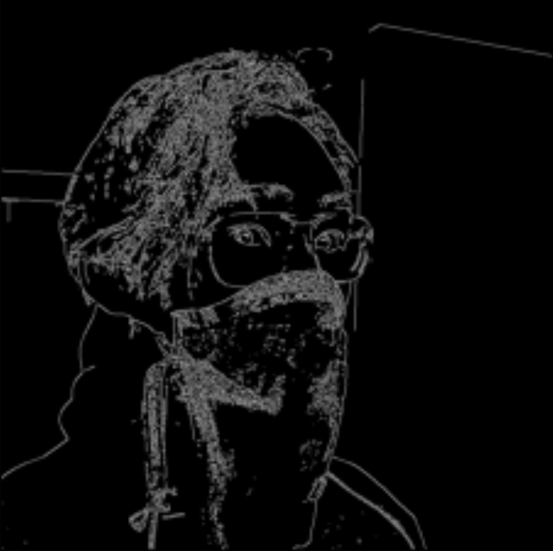
With the ultimate intention of making this project easily replicable, we tried to make software as simple, efficient, and effective as possible. We utilize OpenCV to do much of the proprietary image processing. Using OpenCV, we can import our image, convert it to grayscale, perform edge detection, and generate contours. The grayscale conversion and edge detection are not necessary for contour generation, but we found this combination yielded the best results through experimentation. Once our images have successfully been converted to contours, we convert the contour array of ints to floats. This float conversion enables us to normalize our image with respect to the height or width of the image so it can then be rescaled to fit within the constraints of our plotter's drawing range. The contour array stores each line, represented as coordinates, in a sub-array. This allows our program to know when to drop and lift the pen. Once our image has been normalized, we can scale and shift it through some simple geometry such that the resulting drawing is as large as possible.
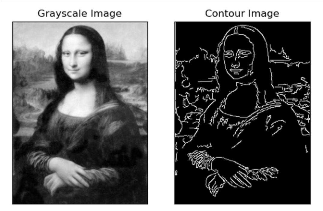
Fig.5 Image Processing Example
With our images now decomposed into a series of x and y coordinates, we were responsible for developing a method for our robotic arm to find these points. We achieved this using inverse kinematics equations. The code implements the following two equations.
\[q_2= cos^{-1}(\frac{x^2+y^2-l_1^2-l_2^2}{2l_1l_2})\]
\[q_1= tan^{-1}(\frac{x}{y})-tan^{-1}(\frac{l_2sin(q_2)}{l_1+l_2cos(q_2)})\frac{x^2+y^2-l_1^2-l_2^2}{2l_1l_2}\]
Using these equations, we can convert x and y coordinates into the angular position for our motors. Then, to draw images, we iterate through our contour array, convert each point into desired angles and command the motors to move to the desired angular position.
To control the motor, we used the “RpiMotorLib” library. This library has no direct support for the DRV8834, but the A4988 configuration included in the library was sufficient and compatible with our motors. We created a Python class “Arm” for each motor, inside of which it stores the motor object and the current angle of the motor. For the class-specific functions, we have to_angle, which takes in an angle, moves the arm to that position, and updates the current angle. It was important to consider that the input angle could be an unachievable value for the motor, considering it has a finite number of steps. Therefore we update the angle value with respect to the number of steps we take instead of setting it to be the input angle. This prevents accumulating errors.
To move the two motors simultaneously, we utilized the Python threading library. Finally, we defined a function draw_array(), which iterates through the input array of points, calculates the motor angle, moves the arms to that position, and drops the pen creating a dot.
For testing, we also created functions like make_circle and make_rectangle to produce an array of points that, when drawn, should create a circle or rectangle of various dimensions.
Result
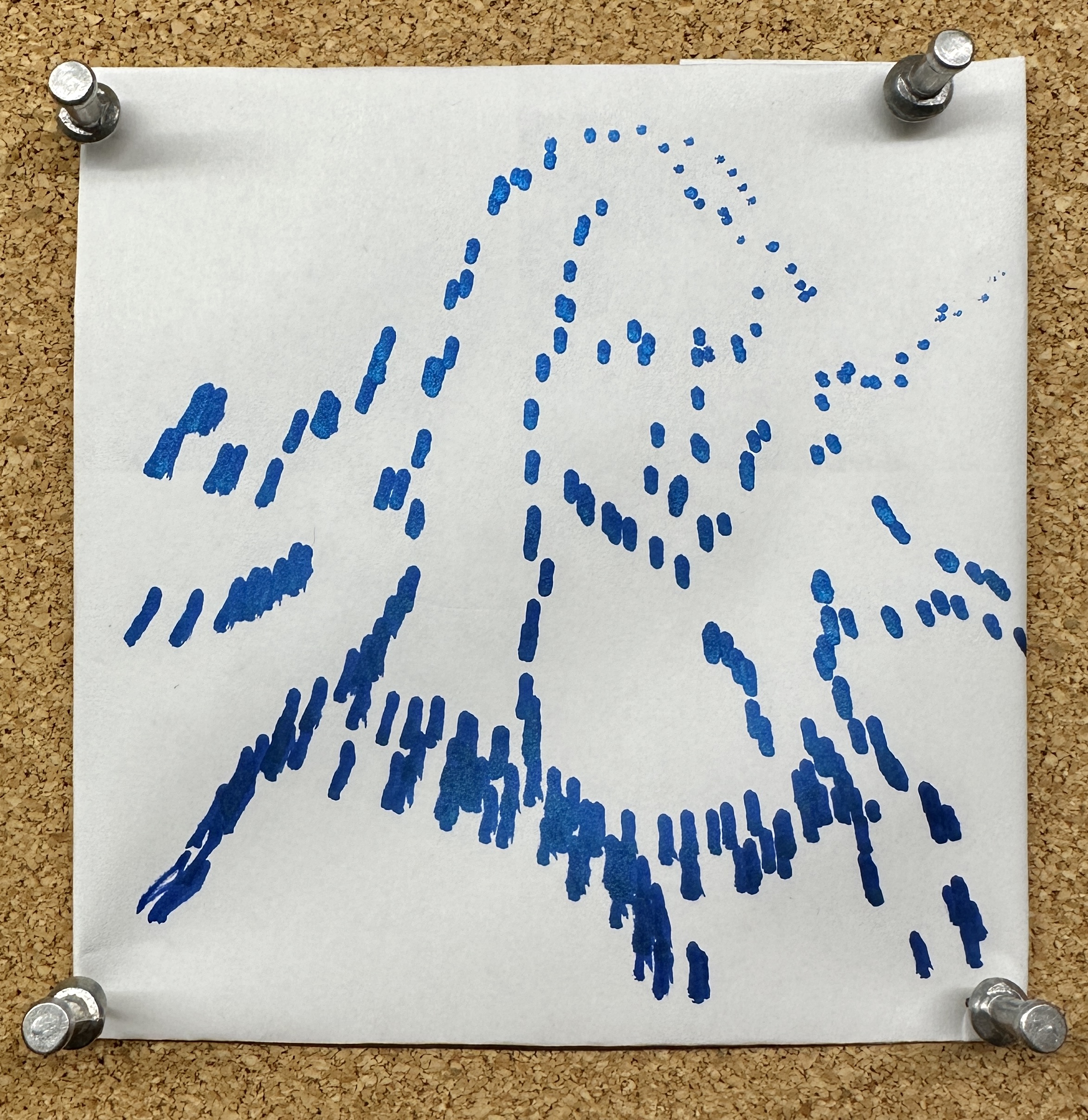
During development, we encountered many issues, the most challenging of which were faced during final integration. Considering our design includes a mechanical arm, we ran into significant problems relating to the torque being applied to the motors by the freely floating arms. In certain circumstances, this hindered their ability to move successfully and, in some cases, skip steps. As a result of this, we spent a considerable amount of time experimenting with different motors and motor configurations. This proved to be very time-consuming as with each new variation; we needed to redesign the system in CAD. Even in our final design, we were unable to overcome the friction issues and, therefore, unable to drag the pen across the page successfully. This forced us to change the scope of our project for the final demo, such that our plotter now constructed images by making dots. In doing this, we could still display and highlight many of the key features of our design.
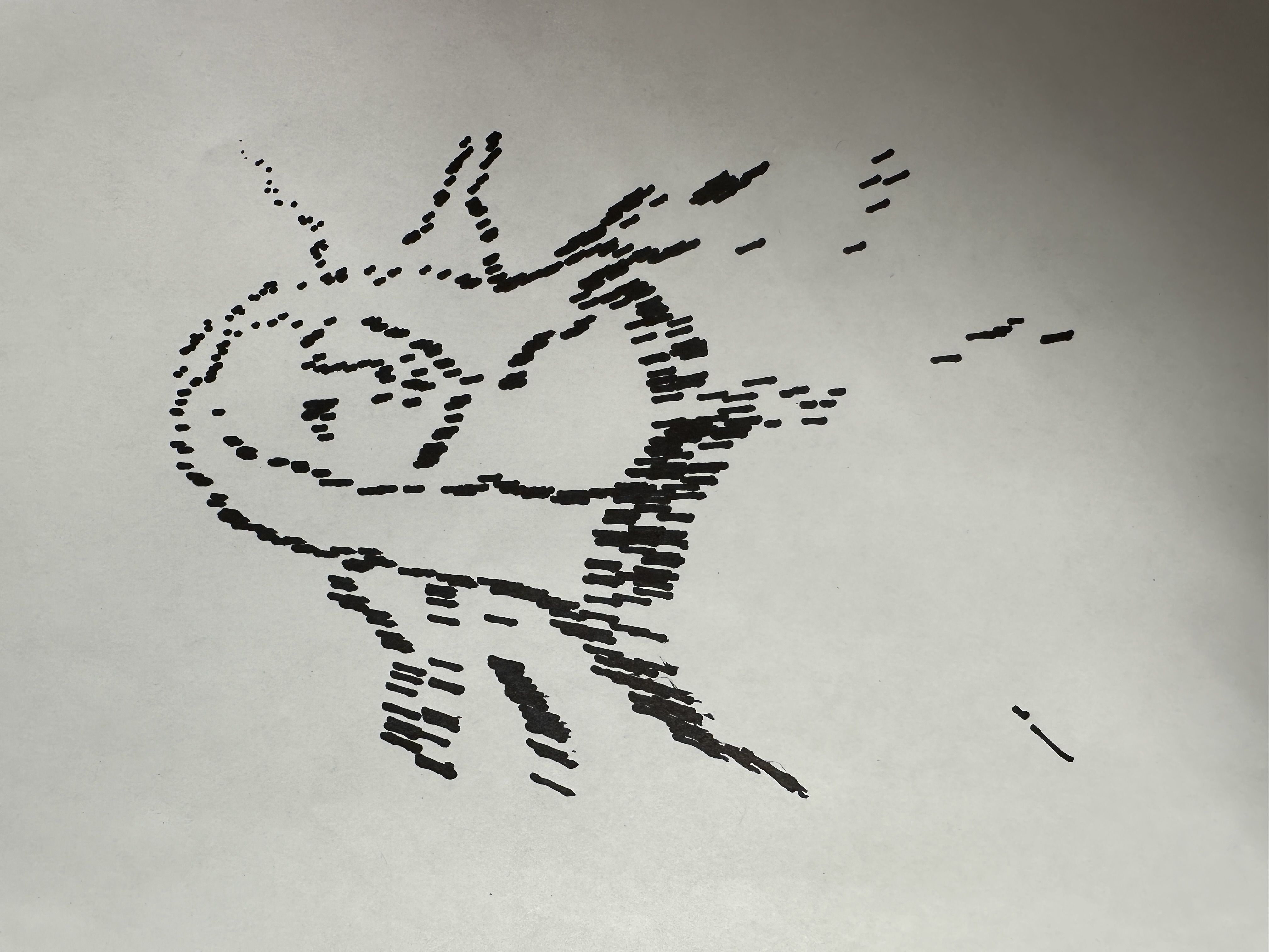
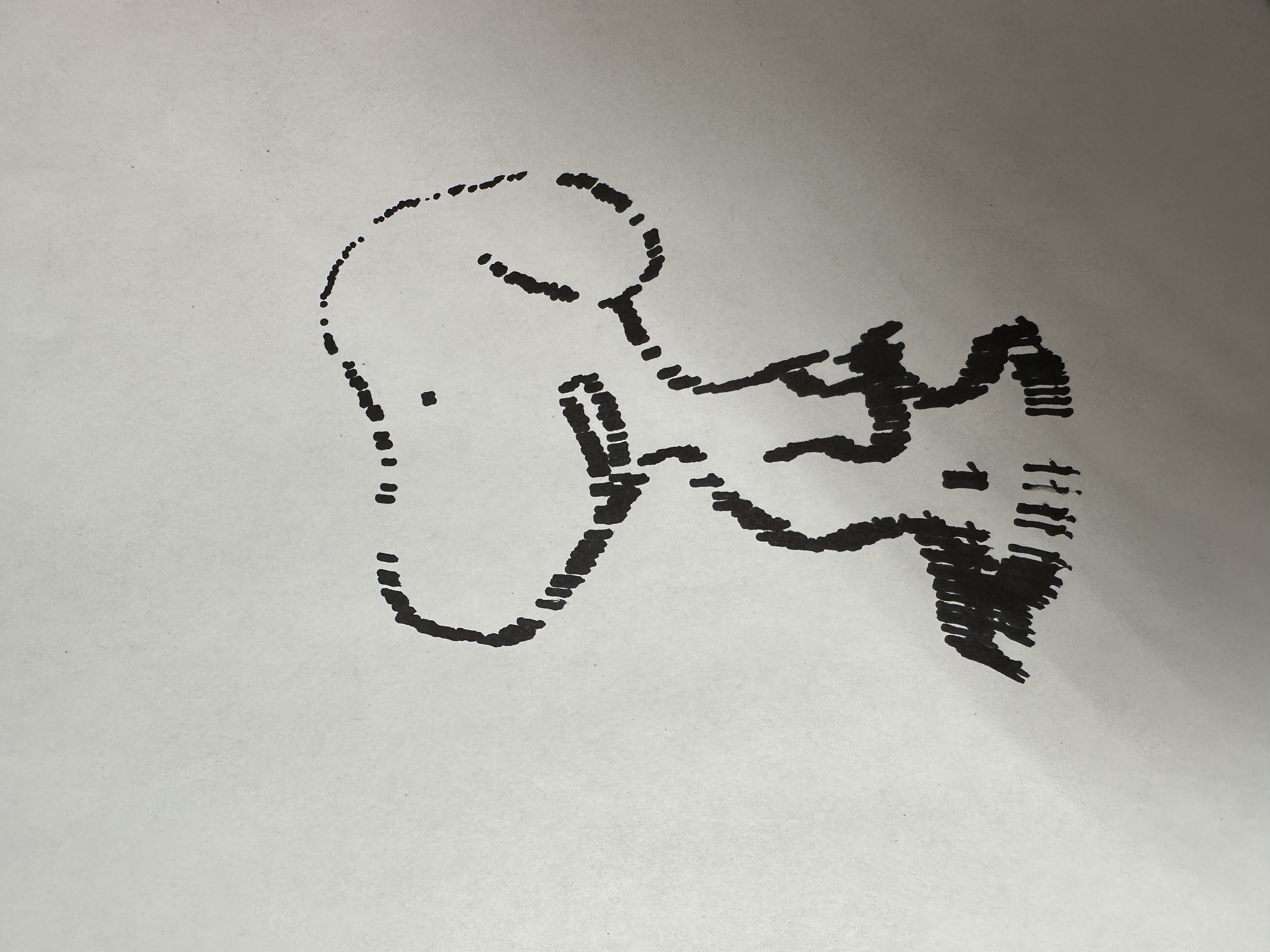
Fig.6 Drawing Examples - Mona Lisa and Snoopy Dog
Calibration was also a very time-consuming endeavor, which required us to do a significant amount of revision relating to arm length and motor control. We had to redesign motor control to prevent confounding or accumulating errors resulting from the stepper motor's inability to precisely achieve the desired angles. Furthermore, the arm's understanding of the coordinate system is defined by the arm lengths used in the inverse kinematics equations. Therefore, small inconsistencies between the actual arm lengths and the arm lengths in the code resulted in skewed and inconsistent images. Because both motors influence vertical and horizontal position, skew could not be accounted for by vertically or horizontally scaling the image. Because the pen doesn’t land vertically on the page, the length of arm 2 is not accurately represented by the CAD dimensions and had to be found experimentally.
Future Work
If we had been afforded more time to complete this project, we would have ultimately pivoted away from the robotic arm design. The challenge with this design is that its rectangular drawing range requires the arm to be significantly longer than the respective dimensions of the rectangle. Furthermore, as the size of the rectangle grows, it puts more torque on the first motor, requiring it to be larger and more powerful. Because of the need for bigger and more expensive parts to create images of reasonable size, the project's scope moves away from our initial goal of a cheap and replicable device. A hanging design would be more optimal. Although it may have a larger footprint, it can utilize the same components and produce larger images while forging many of the frictional challenges we encountered.
Work Distribution
Deemo(Yizhou) Chen
yc938@cornell.edu
Hardware Design and Motor Control Software

Sabian Grier
srg293@cornell.edu
Software(Algorithm) and Testing.
Parts List
- Raspberry Pi $35.00
- DRV8834 Low-Voltage Stepper Motor Driver Carrier * 2 - $9.95*2
- NEMA 14 Stepper Motor: Bipolar, 200 Steps/Rev, 28×45mm, 4.5V, 0.67 A/Phase - $30.95
- NEMA 17 Stepper Motor: Bipolar, 200 Steps/Rev - Provided in Lab
- Micro Servo - High Powered, High Torque Metal Gear - TowerPro MG92B - $11.95
- Wires and Capacitors - Provided in Lab
Total: $97.8
Code Appendix
//Plotter.py
import RPi.GPIO as GPIO
from RpiMotorLib import RpiMotorLib
import numpy as np
import time
from threading import Thread
import cv2
import math


l1 = 10 #length of first arm
l2 = 11 #length of second arm

#define GPIO pins
GPIO_pins = (-1, -1, -1) # Microstep Resolution MS1-MS3 -> GPIO Pin
GPIO.setmode(GPIO.BCM)
GPIO.setup(18, GPIO.OUT)

lift=GPIO.PWM(18, 50)
lift.start(0)

direction1= 21 # Direction -> GPIO Pin
step1= 20 # Direction -> GPIO Pin

step2 = 24 # Step -> GPIO Pin
direction2= 23 # Direction -> GPIO Pin

###BUTTONS####
pause_pin = 17
paused = False

def button_cb(channel):
global paused
if(paused):
print("cont...")
paused=False
else:
print("paused")
paused=True


GPIO.setup(pause_pin, GPIO.IN, pull_up_down=GPIO.PUD_UP)
GPIO.add_event_detect(pause_pin, GPIO.FALLING, callback = button_cb, bouncetime=300)
##############
offset = 3.2625+1.6
img = cv2.imread('imgs/mona.jpeg', cv2.IMREAD_GRAYSCALE)
edges = cv2.Canny(img,100,200)
height, width = edges.shape
height = float(height)
width = float(width)
contours, hierarchy = cv2.findContours(edges, cv2.RETR_TREE, cv2.CHAIN_APPROX_SIMPLE)


max_r = 15

input_r = np.sqrt(height**2+width**2)

scale_factor = max_r/input_r


#converts the points stored in contours from ints to floats
contours_float = []
for contour in contours:
contour_float = contour.astype(np.float32)
contours_float.append(contour_float)

#normalizes all points with respect to width and height of the image
for contour in contours_float:
contour[:, :, 0] *= scale_factor
contour[:, :, 1] *= scale_factor

# Get x and y coordinates of contour points
x_coords = []
y_coords = []
for contour in contours_float:
for point in contour:
x = point[0][0]
y = point[0][1]
x_coords.append(x)
y_coords.append(y)

coordinates = [[x, y] for x, y in zip(x_coords, y_coords)]

class Arm:
  def __init__(self,angle, motor):
    self.angle = angle
    self.motor = motor

  def to_angle(self, angle):

    angle_diff = np.abs(angle-self.angle)
    step = int((angle_diff*200*16/360))

    if(self.angle>=angle):
      self.motor.motor_go(True, "1/16" , step, 0.01, False, .05)
      self.angle-=step*(360/(200*16))

    else :
      self.motor.motor_go(False, "1/16" , step, 0.01,False, .05)
      self.angle+=step*(360/(200*16))


def anglecalc(x,y):
  theta2 = np.arccos(((x**2 + y**2 - l1**2 -l2**2)/(2*l1*l2)))

  if x == 0:
    theta1 = np.pi/2 - np.arctan((l2*np.sin(theta2))/(l1 + l2 * np.cos(theta2)))
  else:
    theta1 = np.arctan(y/x) - np.arctan((l2*np.sin(theta2))/(l1 + l2 * np.cos(theta2)))

  if(theta1>np.pi/2):
    theta1 = theta1 - np.pi

  print("angle1: "+str(theta1*180/np.pi))
  print("angle2: "+str(theta2*180/np.pi))
  print("x: "+str(x))
  print("y: "+str(y))
  print("------------------------------------")
  return theta1*180/np.pi, theta2*180/np.pi


# Declare an named instance of class pass GPIO pins numbers
motor1 = RpiMotorLib.A4988Nema(direction1, step1, GPIO_pins, "A4988")
motor2 = RpiMotorLib.A4988Nema(direction2, step2, GPIO_pins, "A4988")
arm1 = Arm(0,motor1)
arm2 = Arm(0,motor2)


def move_both_arm(angle1, angle2):
  arm1_t = Thread(target=arm1.to_angle, args=(angle1,))
  arm2_t = Thread(target=arm2.to_angle, args=(angle2,))
  arm1_t.start()
  arm2_t.start()
  arm1_t.join()
  arm2_t.join()


def pen_touch(touch):
  if(touch==True):
    lift.ChangeDutyCycle(5)
    time.sleep(0.1)
  else:
    lift.ChangeDutyCycle(6.5)
    time.sleep(0.1)


def to_point(x,y):
  angle1, angle2 = anglecalc(x, y)
  move_both_arm(angle1,angle2)

def draw_array(arr, arm1, arm2):
  global pasued

  for i in range(len(arr)):
    while(paused):
    time.sleep(0.5)

    print("drawing point #:"+str(i))
    to_point(arr[i][0],arr[i][1])

    time.sleep(0.3)

    pen_touch(True)
    pen_touch(False)
    pen_touch(False)


# r->radius, x y center, n number of points
def make_circle(r, x, y, n):
  angles = np.linspace(0, 2*np.pi, n)
  out = [[x + r*np.cos(theta), y + r*np.sin(theta)] for theta in angles]
  return out

def make_rectangle(w, h, x, y, n):
  xs = np.linspace(x, x + w, n)
  ys = np.linspace(y, y + h, n)
  bottom = [[xi, y] for xi in xs]
  top = [[xi, y + h] for xi in xs]
  left = [[x, yi] for yi in ys]
  right = [[x + w, yi] for yi in ys]
  left.reverse()
  return bottom + right[1:-1] + top[::-1] + left[1:-1]


#LINE DEMO

line_array = []
for i in range(50):
  line_array.append([5+offset,2+i])

line_array =
[[10,5],[10,10],[7,7],[10,5],[10,10],[7,7],[10,5],[10,10],[7,7],[10,5],[10,10],[7,7],[10,5],[10,10],[7,7],[10,5],[10,10],[7,7],[10,5],[10,10],[7,7]]

# line_array =[[offset,offset],[offset,10],[10,offset],[10,10]]
# draw_array(line_array,arm1,arm2)

#CIRCLE DEMO

circle = np.array(make_circle(4,8+offset,5+offset,20))
# draw_array(circle,arm1, arm2)


# RECTANGLE DEMO
rect = make_rectangle(5,5,offset+3,offset+2,5)

# draw_array(rect,arm1,arm2)

# IMG
img_arr=[]

## DOWNSAMPLE
for i in range(np.array(coordinates).shape[0]):
  if i % 100 ==0:
  offsetted = [coordinates[i][0]+offset,coordinates[i][1]+offset]
  img_arr.append(offsetted)


img_arr= np.array(img_arr)
draw_array(img_arr, arm1, arm2)


####ENDING#####
to_point(12,0)
pen_touch(False)

lift.stop()
GPIO.cleanup()