Rescue Robot: Scouting Owl
Robby Huang (lh479) | Parth Sarthi Sharma (pss242)
ECE 5725 | May 19, 2021
Demonstration Video
Project Objective
In incidents such as gas leakage, nuclear explosion, or any environment that has potential threats to the life of the rescuer, a rescue robot can play an important role in searching for survivors and studying the hazardous conditions. We need a robot that can detect survivors, avoid obstacles, scouting the environment, and communicate with survivors in extreme environments.
Introduction
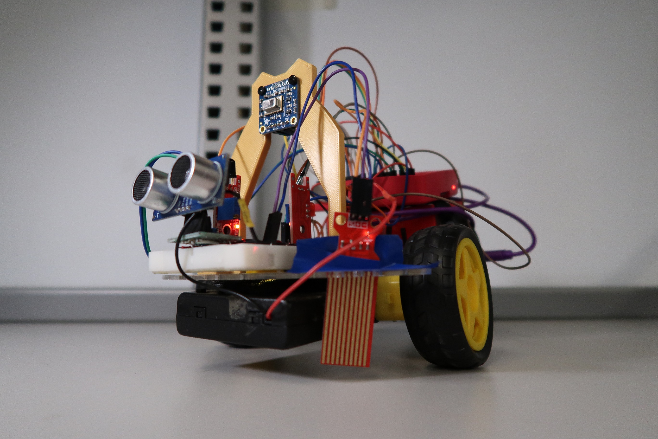
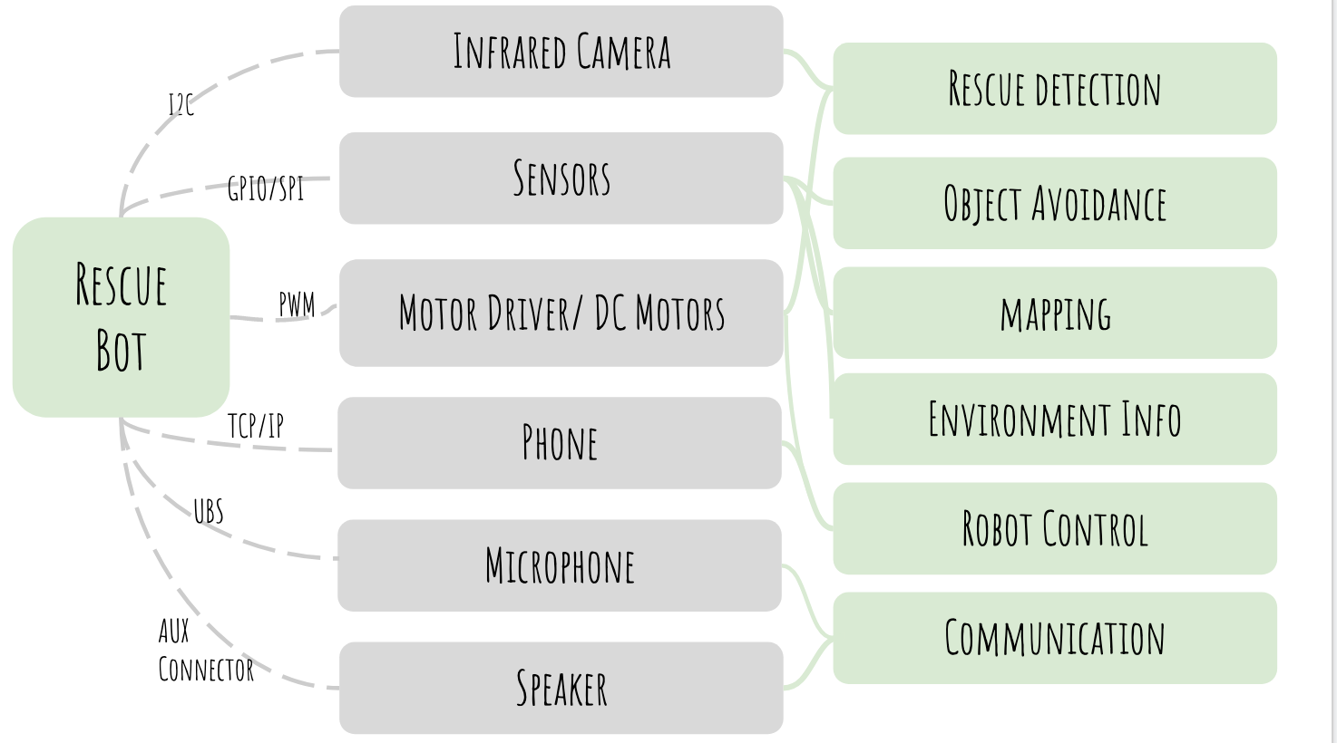
Scouting Owl is a robot that allows the rescuers to detect and communicate with the survivor in an environment that is not yet suitable for in-person rescue. To perform the critical rescue task, we built a Raspberry Pi 4 based robot with the following functions:
- Establish a reliable half-duplex connection between the robot and the control device.
- Fetch and display live IR camera feed along with sensor data on the display device.
- Send commands from the control device to the robot.
- Implement a function for the robot to map the surrounding area and display the map on the screen.
Hardware Design
The diagram below shows the wiring of our system. We used both 5V and 3.3V to power sensors depending on their operating voltage. For the sensor that is taking 5V, we use resistors to divide its output voltage to protect the GPIO pins on Raspberry Pi.
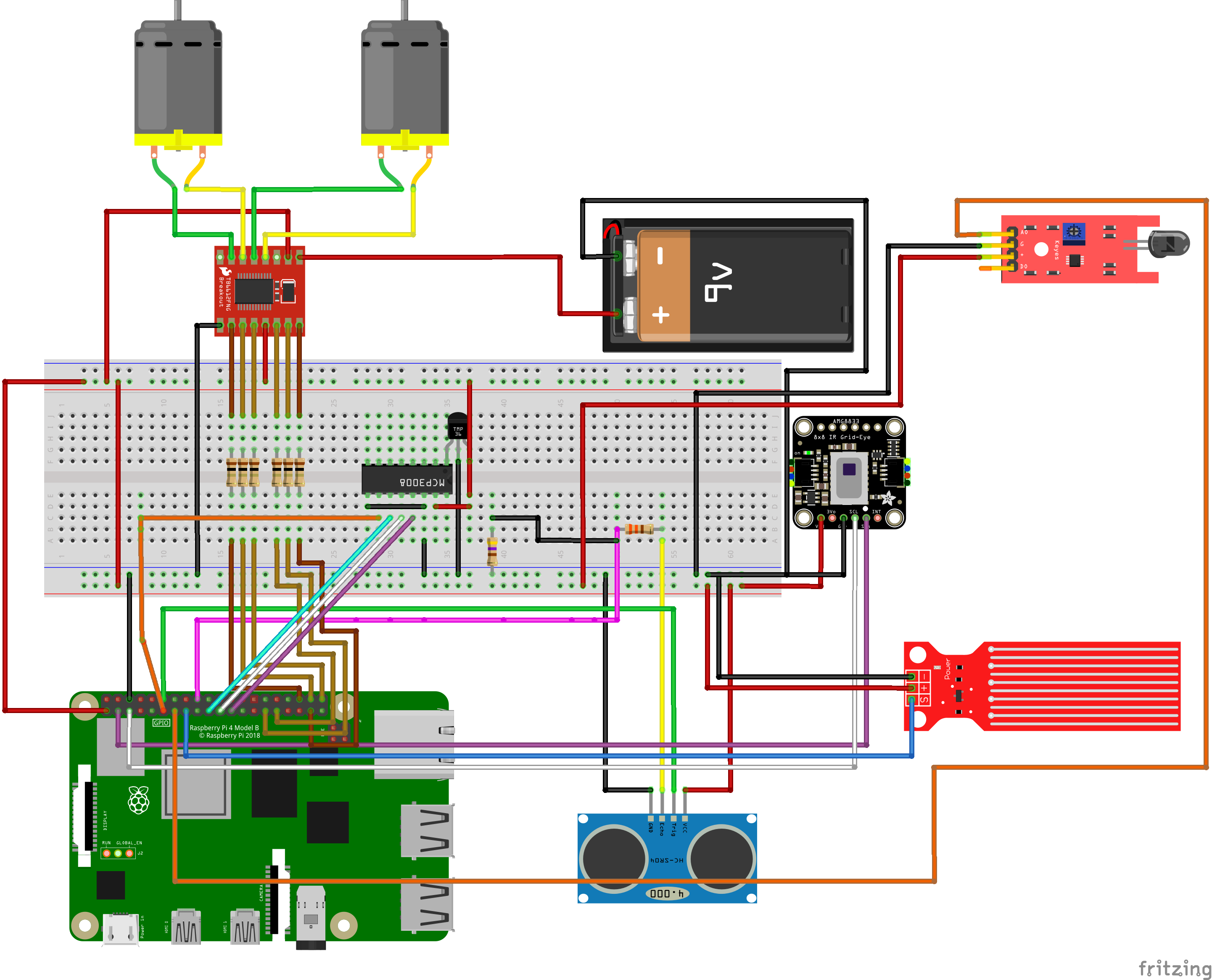
Circuit connection of all the components
Infrared Thermal Camera
To get a live feed of our surroundings, we used the Adafruit AMG8833 IR Thermal Camera. This camera module has 12 pins, out of which we only used 4. To get data from the camera, we used the I2C communication protocol. We also needed to install the "adafruit_amg88xx" library to use the module. Once running, the module returns an array of 64 individual infrared temperature readings over I2C. This module can measure temperatures ranging from 0°C to 80°C with an accuracy of +- 2.5°C making it ideal for our application. It can also detect a human from a distance of up to 7 meters. In order to get an image from the 8x8 array, we used image processing using the SciPy python library to interpolate the 8x8 grid. We used Fusion 360 to CAD an owl shape mounting mechanical to mount the IR camera securely and enhance the aesthetic of the robot.
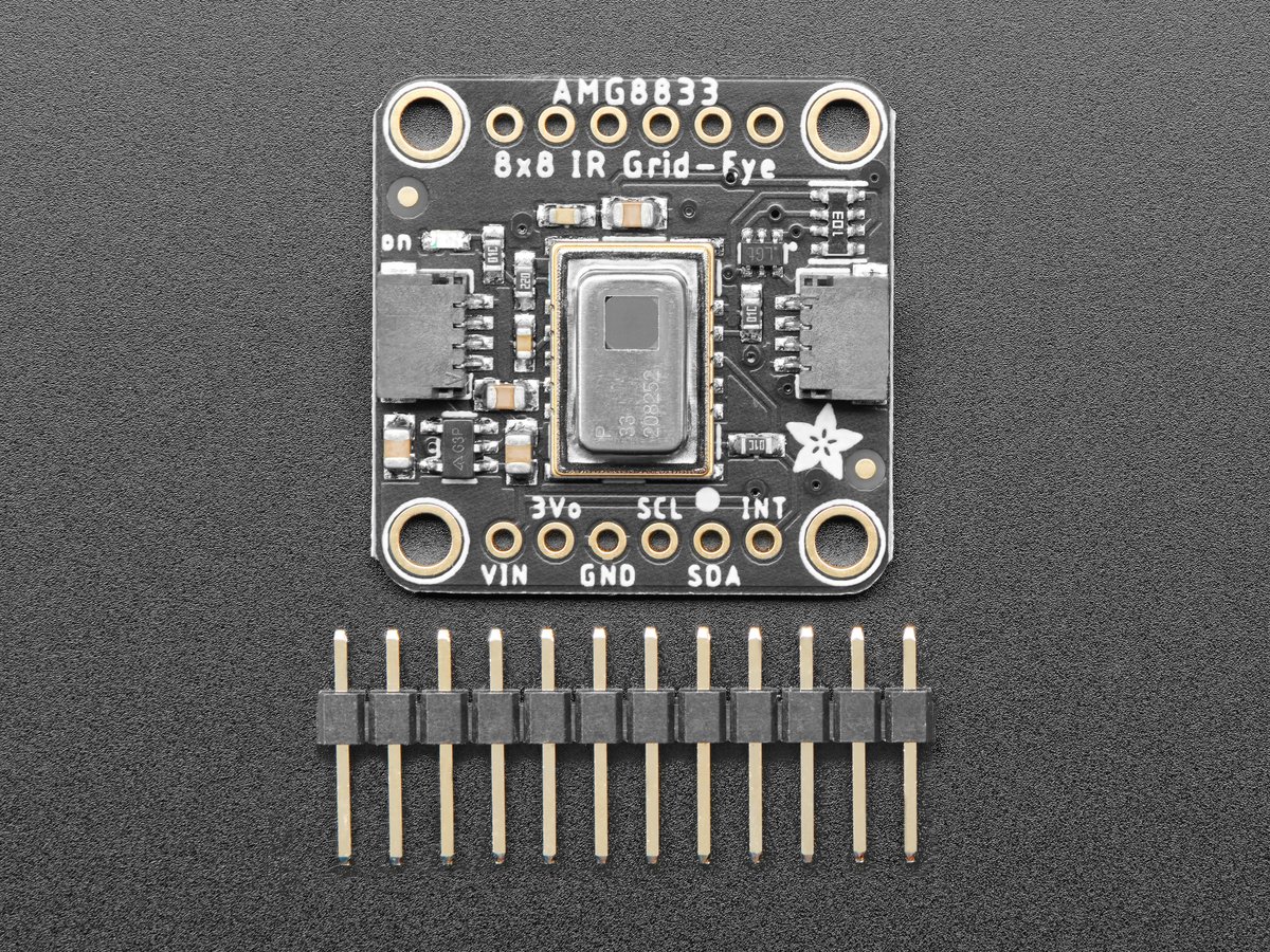
The IR Thermal Camera
We used Fusion 360 to CAD an owl shape mechanical mount and 3D printed it to mount the IR camera securely and enhance the aesthetic of the robot.
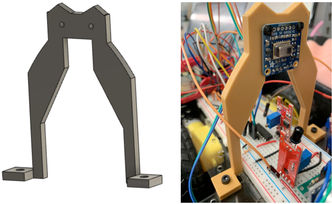
The IR Camera Mount
Implementing Sensors
Along with the IR camera, our rescue robot is equipped with the following sensors:
- The flame sensor: We used the flame sensor to see if there is any fire nearby. If so, the rescuers are alerted about it on the display device. This sensor gives out a digital output corresponding to whether a fire is present or not. In order to receive the output, we used an edge-triggered callback function because it saves precious CPU cycles.
- The water sensor: We used the water sensor to see the presence of water. Since our robot is an electronic device, it is prone to short circuits when it comes in contact with water. Similar to the flame sensor, this sensor gives out a digital output corresponding to whether water is present or not. To receive the output, we used an edge-triggered callback function because it saves precious CPU cycles.
- The radiation sensor: We added a long wire connected to a free GPIO pin to utilize the above phenomenon. This wire acts as an antenna and can detect such bursts of radiation. To test our hypothesis, we hooked up the wire to an oscilloscope and tested the result. We found out that it does detect EM discharges.
- The temperature sensor: In order to get a measurement of the temperature, we used the LM393 temperature sensor. This sensor gives out a raw ADC value which needs to be converted into the corresponding temperature value using the expression: $$temperature = 10 * log_{10}(10000 * (\frac{3.3 * 1024}{adc} - 1)) - 10$$
- The ultrasonic sensor: In order to keep a track of the distance, we used the HC-SR04 ultrasonic sensor. This sensor has a range of about 2 meters beyond which its accuracy starts decreasing rapidly. The purpose of this sensor is to avoid collisions and map the area around the robot.
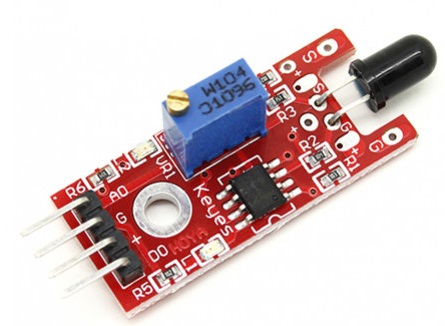
The Flame Sensor
The Water Sensor
Initially, while testing the flame sensor we were using a piezo-electric barbeque lighter. We were hoping to see the results we wanted to see. However, we found out that the lighter triggered both flame and the water sensor and all for the wrong reasons. After debugging for hours, we found out that the lighter we were using generated thousands of volts for a short period which resulted in the generation of EM waves. These waves were intercepted by the wires acting as an antenna which triggered the interrupts.
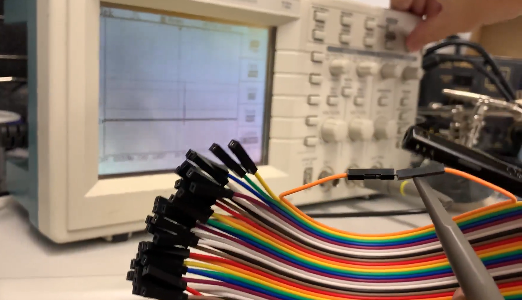
Radiation Output on the Oscilloscope
The Temperature Sensor
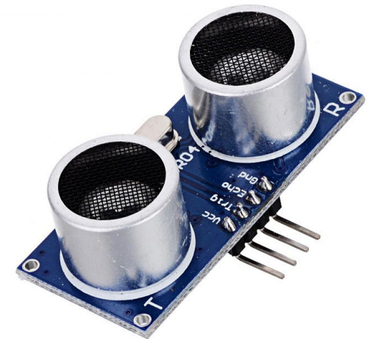
The Ultrasonic Sensor
Moreover, we modularized the voltage divider part of our ultrasonic sensor and used a protoboard to provide both mechanical and electrical connections with the breadboard.
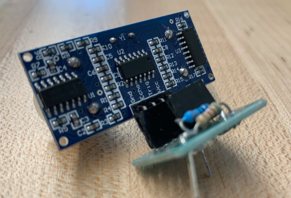
The Modularized Ultrasonic Sensor
The Speaker
In order to communicate with the person being rescued, we also added a Bluetooth speaker which can be controlled directly from the Python script. To play and record audio, the rescuer can simply tap the corresponding button on the screen and control the audio playback.
Software Design
The software design of the project consists of two main parts:
- The Python program running on the Raspberry Pi.
- The Android application running on the user device.
The main architecture of the software design is based on the fact that the Android app and the Python program communicate with each other over a TCP/IP server. The Python program creates a TCP/IP server and opens up a socket for communication. Once the socket is created, it listens and waits for clients to connect to it. Once a client is connected to the server, the main Python program starts executing. During each cycle of execution, the data packet that is sent consists of the following components:
- The IR camera feed:
- The pixel array
- The bicubics array
- The colour array
- The sensor values:
- The water sensor data
- The fire sensor data
- The radiation sensor data
- The temperaure sensor data
- The ultrasonic data
The Python Program
All these different data values are semi-colon (";") delimited and the values in the same data array are comma (",") delimited. All these data points are appended in a single string. The string is then encoded and sent over the TCP/IP socket. After sending the data, the server then waits for the commands from the client in a blocking manner. Once a string is received, the server decodes the string and changes the functions as per the received command.
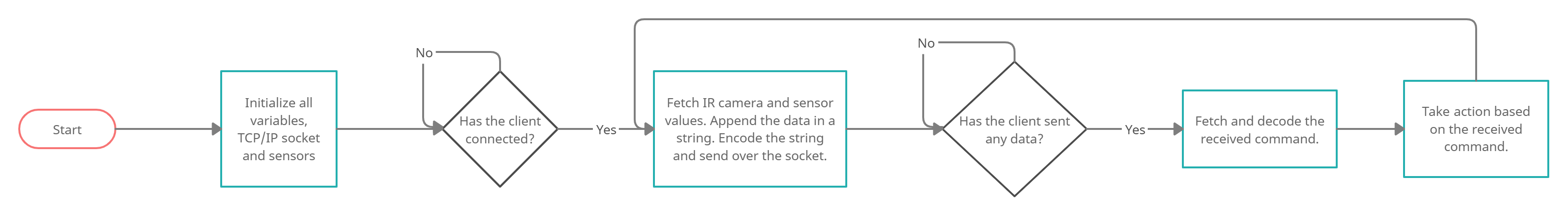
The Flow Diagram for the Python Program
The Ultrasonic Sensor
Ultrasonics sensor uses the time of flight of sound to measure distance. We sent a 0.01 millisecond pulse to the trigger pin of the ultrasonic sensor and took input from the echo pin. Then used the time difference between the trig output and echo input to calculate the distance traveled of the sound back and forth from the detected object and divided that by two. Then we simply used the expression: $$distance = speed \times time$$
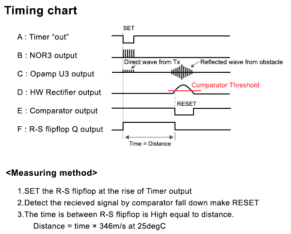
The Timing Diagram for the Ultrasonic Sensor
The ADC
We used an MCP3008 to do the analog to digital conversion. It is an 8-channel, 10-bit analog to digital converter. ‘8 channel’ means that it can accept up to 8 different analog voltages. The 10-bit property is the resolution of the ADC, or the precision to which it can measure a voltage. Since the SPI library is broken, we had to implement it from scratch using bitbanging.
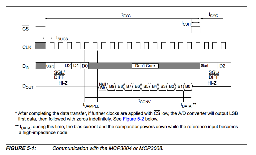
The Timing Diagram for the ADC
Mapping
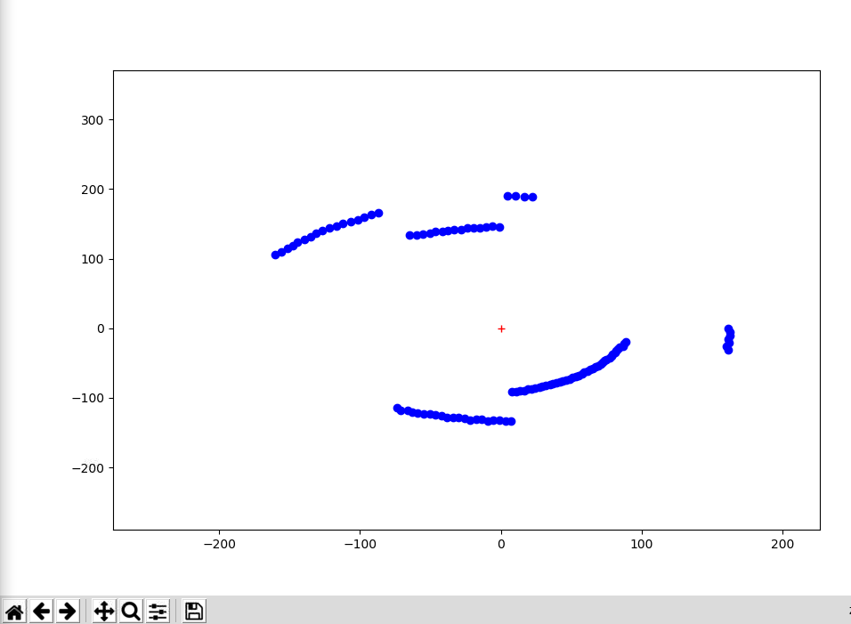
Mapping using only the ultrasonic sensor was challenging as there was no feedback to test how much the robot has moved, so we needed to approach the problem creatively. Since the Scouting Owl is not equipped with localization sensors (IMU or GPS), we needed to make sure we know the robot's position for every measurement data. Therefore, we made the robot turn in place for a complete circle with a fixed number of sample points so that the robot is always at (0,0) and the position can be calculated using the linspace function.
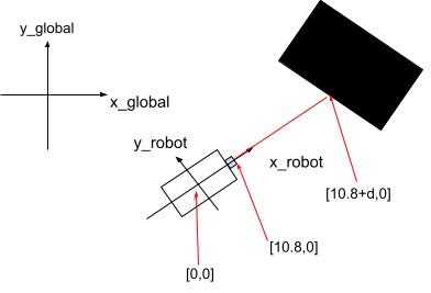
Mapping the Surrounding
With the robot position and the coordinate of the measurement point in the robotic frame, we are able to convert that coordinates into the global frame using a rotation matrix and map all of them.
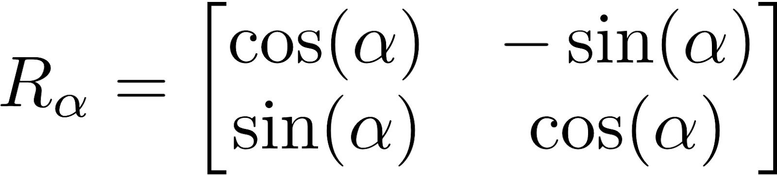
Conversion of Robot Coordinates to Global Coordinates
The Android Application
The Android application works similarly. When the client starts, it searches for the server with the given credentials. Once it is connected to the server, it waits for data to be received in a blocking manner. Once the data is received, the client decodes the data, splits it into IR camera feed and sensor values, and updates the values on the screen. Once the screen has been updated, the client checks for button presses. If a button has been pressed, the client encodes the associated command and sends it over to the server. Otherwise, it encodes the stop command and sends the command over to the said server.
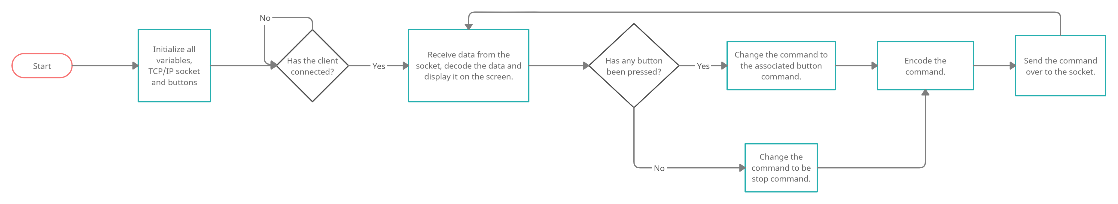
The Flow Diagram for the Android Application
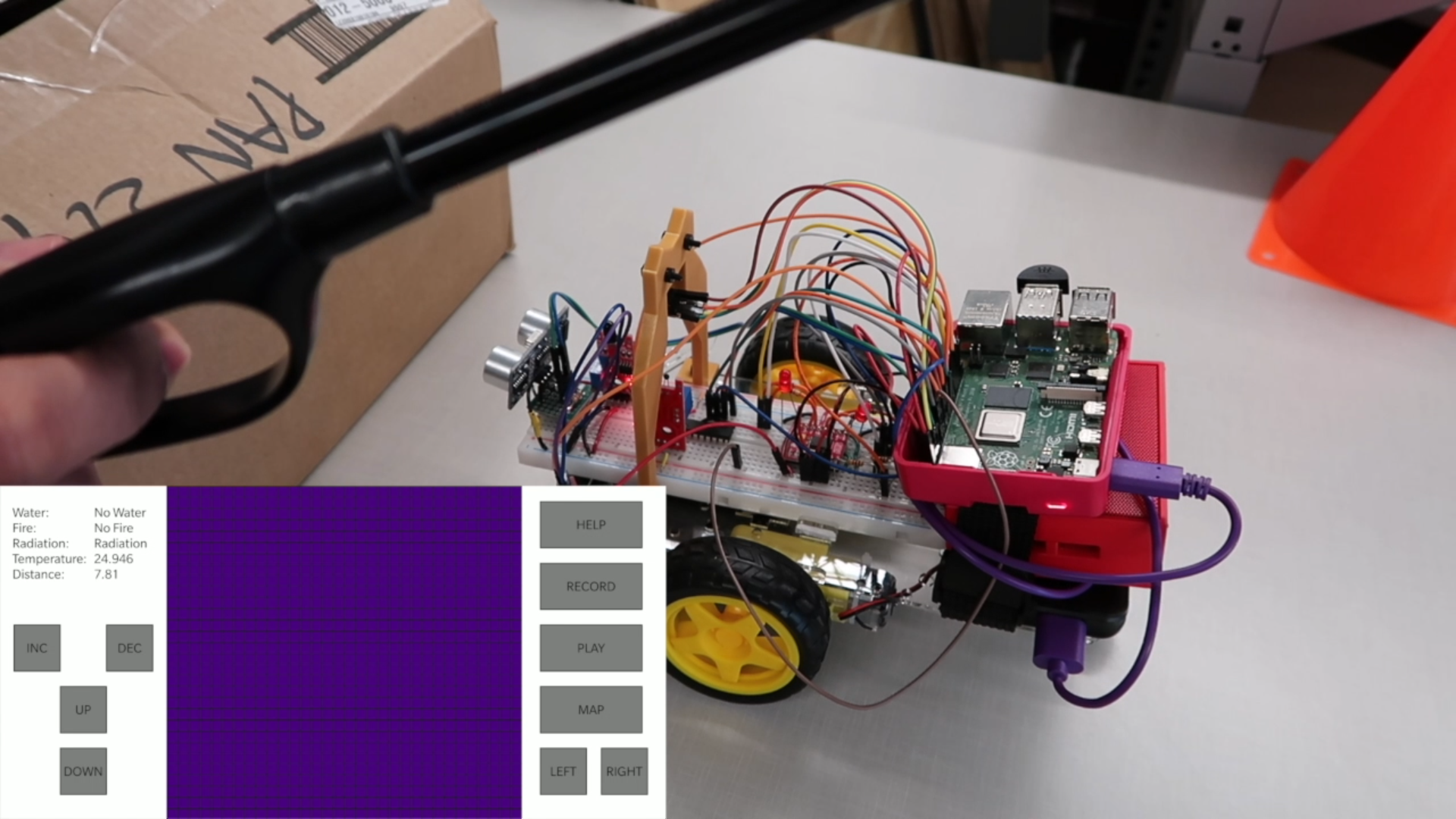
The Android application has a very minimalistic design. It shows the IR camera feed in the center with a data display panel. This panel is used to view the data received from all the sensors. It also has 10 buttons:
- UP: Pressing the UP button moves the robot forward.
- DOWN: Pressing the DOWN button moves the robot backwards.
- LEFT: Pressing the LEFT button rotates the robot in the counter-clockwise direction.
- RIGHT: Pressing the RIGHT button rotates the robot in the clockwise direction.
- INC: Pressing the INC button increases the robot move speed.
- DEC: Pressing the DEC button reduces the robot move speed.
- HELP: Pressing the HELP button plays a pre-recorded message.
- RECORD: Pressing the RECORD button prompts the person being rescued to record their message.
- PLAY: Pressing the PLAY button plays the sound recorded by the person being rescued.
- MAP: Pressing the MAP button creates a map of the surrounding area.
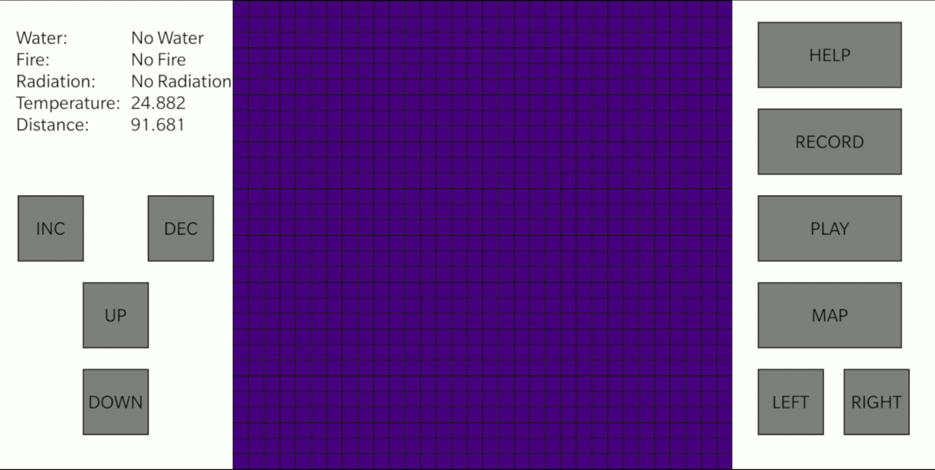
The Android Application
The biggest challenge while implementing the said algorithm was that the Wi-Fi router at our apartment was blocking the TCP/IP packets and therefore, wasn't allowing the connection between the server and the client to be established. In order to tackle this problem, we simply connected the RaspberryPi and the Android device to Cornell's open "RedRover". This allowed us to implement the system quite effectively.
Another challenge we faced on the software side was that connecting to RedRover didn't allow us to update our kernel or install any new package. The reason behind this is that RedRover needs the users to login using Cornell NetID. Once logged in, we were able to use it like any other network.
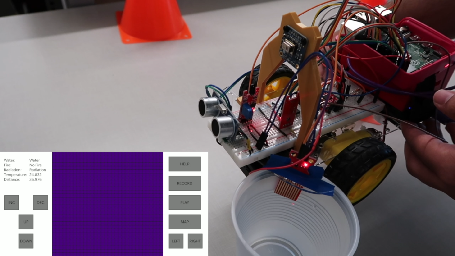
Testing
To ensure that we keep making progress, we strictly followed this checklist so that we could have a smooth workflow and systematic approach to the overall objective.
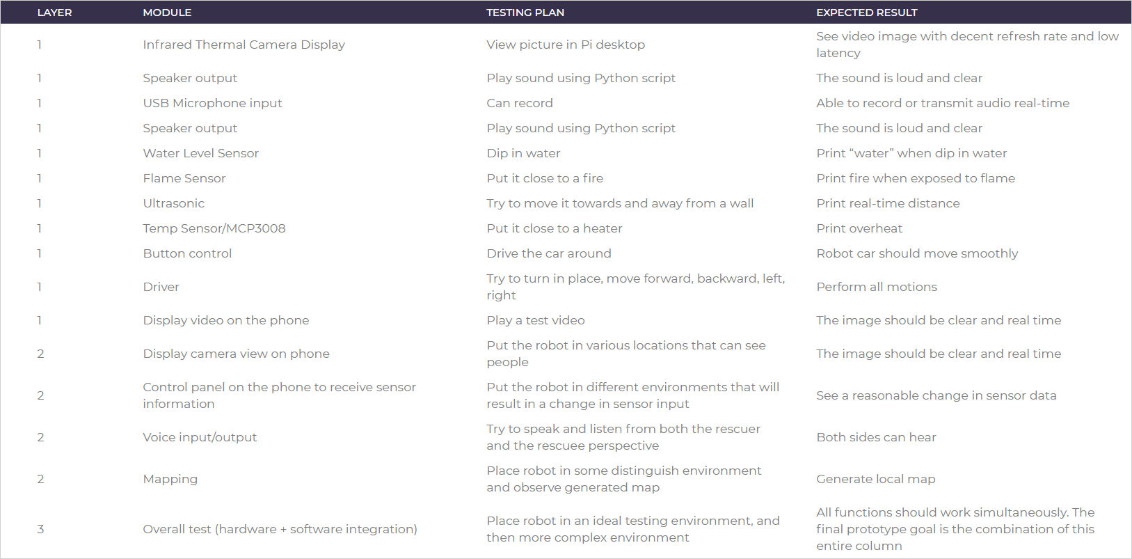
In order to see how well the system works, we tested each and every component quite extensively. We carried out the following tests:
- User control test: As the first step towards testing, we turned the power on and started the program. Then we tested out all the motion control buttons and verified that all the buttons are functioning as they should. We found out that there was a bit of latency because of large data packets being transmitted, but the robot was responding as it should.
- Ultrasonic test: Next, we began testing the ultrasonic sensor to test the accuracy in the measurement of distance. Moreover, as a security feature, we also tested if the robot stops moving forward when the distance between an obstacle and the robot is less than a certain threshold value (15 cms in this case). The test revealed that the distance is accurate within 1 cm for a range of 4 cm to 200 cm. The distance is unmeasurable below 4 cm and the accuracy falls rapidly beyond 200 cm. Moreover, the robot does stop automatically and does not move forward when the distance goes below the set threshold.
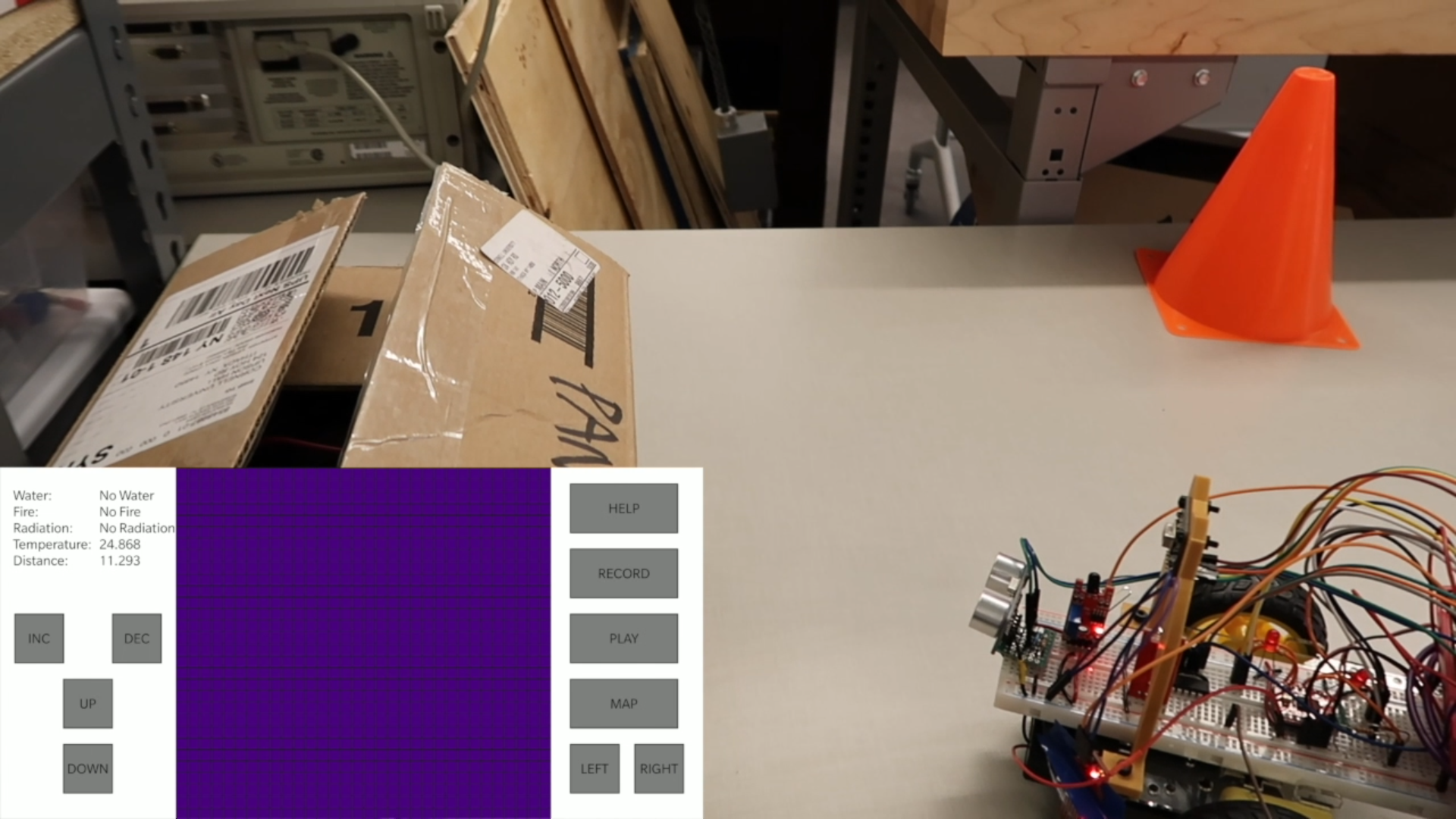
- Flame test: The next sensor we tested was the flame sensor. In order to do so, we used a flint spark lighter and brought the flame close to the sensor. The main objective was to test how quickly the sensor reading changes in response to the flame and to figure out the maximum distance at which the flame is detected. The test revealed that the reading changes almost instantaneously in response to the flame. Also, the sensor is able to detect the lighter flame well over 1 meter when the flame is directly above the flame sensor. We also hypothesize that the distance will be even greater in case of larger flames. However, we did not have the required tools to safely test this out for larger flames.
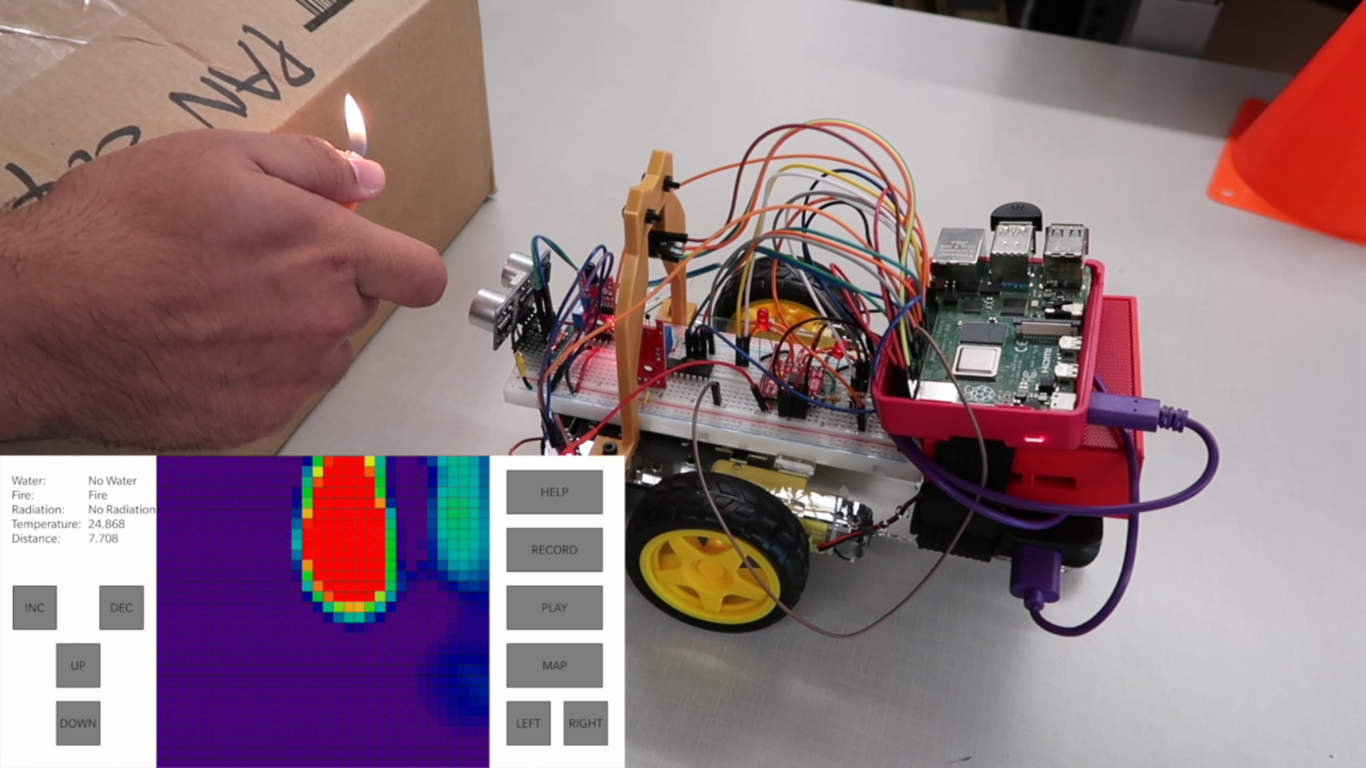
- Water test: In order to safely test the working of the water sensor, we used a cup of water and dipped the water sensor in the cup. The main idea was to test how quickly the sensor detects water. The test resulted in confirmation of the fact that the water is detected as soon as about 0.5 cm of the sensor is dipped in the water.
- Radiation test: In order to test the radiation, we used the piezo-electric barbeque lighter to generate a large voltage discharge. We found out that it was toggling the radiation flag quite effectively. However, it was also mistakenly toggling the flame and water sensor flags. To avoid this, we simply toggled those flags back in the radiation sensor callback and it worked like a charm.
- Mapping test: In order to test how well the mapping works, we placed the robot in a hallway and mapped the hallway for various locations quite extensively. The results of the mapping were generally quite decent with a few inaccuracies. However, the bigger picture was quite comprehensible and understandable.
- Audio test: In order to test the audio output and input, we connected the Bluetooth speaker to the RaspberryPi and played the audio files. We also tested the microphone input by recording the audio messages and playing them back. The audio recordings were quite legible.
Testing of the Ultrasonic Sensor
Testing of the Flame Sensor
Testing of the Water Sensor
Testing of the Radiation Sensor
Running the Map Test
Result
The project progressed mostly as we planned. We were able to implement all the sensors and features that we planned for. Moreover, we were also able to stay on track and save enough time to implement the mapping feature. We were able to develop the data packet structure to send data from server to client and get a response in return. Although there were a few hiccups like a few broken libraries and connection issues due to the router blocking our TCP/IP packets, we were able to figure out the workarounds and stay on track in order to finish the project on time. We also managed to implement the mapping function which was very difficult to get right.
Conclusion
We are proud that all features are well integrated and the user experience is decent. The user can remotely control the robot with their phone over a Wi-Fi network. The Scouting Owl keeps streaming its surroundings with the IR camera and constantly updates sensor information that benefits the rescuer: temperature, water level, and flame. It can even generate a clear local map with only the ultrasonic sensor and can establish back and forth conversations with the rescuee. All the features mentioned are well integrated into the concise Android application. Overall, our project covers a wide range of topics and requires skill sets from computer science (Application development, TCP/IP communication), electrical engineering (sensors, embedded system programming), and mechanical engineering (CAD, 3D printing).
Despite accomplishments, we also learned a lot when getting stuck. We discovered that the communication between the Android device and the Raspberry Pi can not be established in a private Wi-Fi network. We found a lot of broken libraries when trying to integrate sensors which may suggest that a better solution may be using a microcontroller and establishing communication with it. Learning about the limitations and advantages of a Raspberry Pi will help us to make better design choices in future projects.
Future Scope
Although Scouting Owl is in an amazing shape given that it is a month-long project, we can still elevate it in a lot of different ways:
- With the 8 channel ADC converter, we can include more analog sensors that tell us more information about the environment. For example, we can add photo-resistors, humidity sensor, and motion detector.
- As mentioned above, Raspberry Pi is not ideal for directly interfacing with sensors, so using a microcontroller as a data acquisition board and communicating sensor readings with the Pi may be a more optimal and professional solution.
- We can enhance mapping if we use a GPS or IMU to collect information and then use an Extended Kalman Filter to perform localization for the robot. In this way, we can create a much larger map. To map with higher precision, we can use the Intel real sense depth sensor that provides 9 depth measurements from 9 different angles at each time interval.
- We can also implement a feedback mechanism for each motor so that they are closed-loop controlled. To implement that, we can connect an encoder on the motor shaft and then tuned it with a control algorithm such as PID. A closed-loop controlled motor moves more gradually and will allow sensors to collect more accurate data.
Budget
- AMG8833 IR Thermal Camera: $26.99
- Mini USB Microphone: $5.95
- JBL Go Speaker: $10.00
- Water Level Sensor, Flame Sensor, Analog Temperature Sensor Ultrasonic: $10.00
- MCP3008: $3.75
- Raspberry Pi 4: $35.00
- Robot Kit: N/A
- Overall: $91.69
Work Distribution
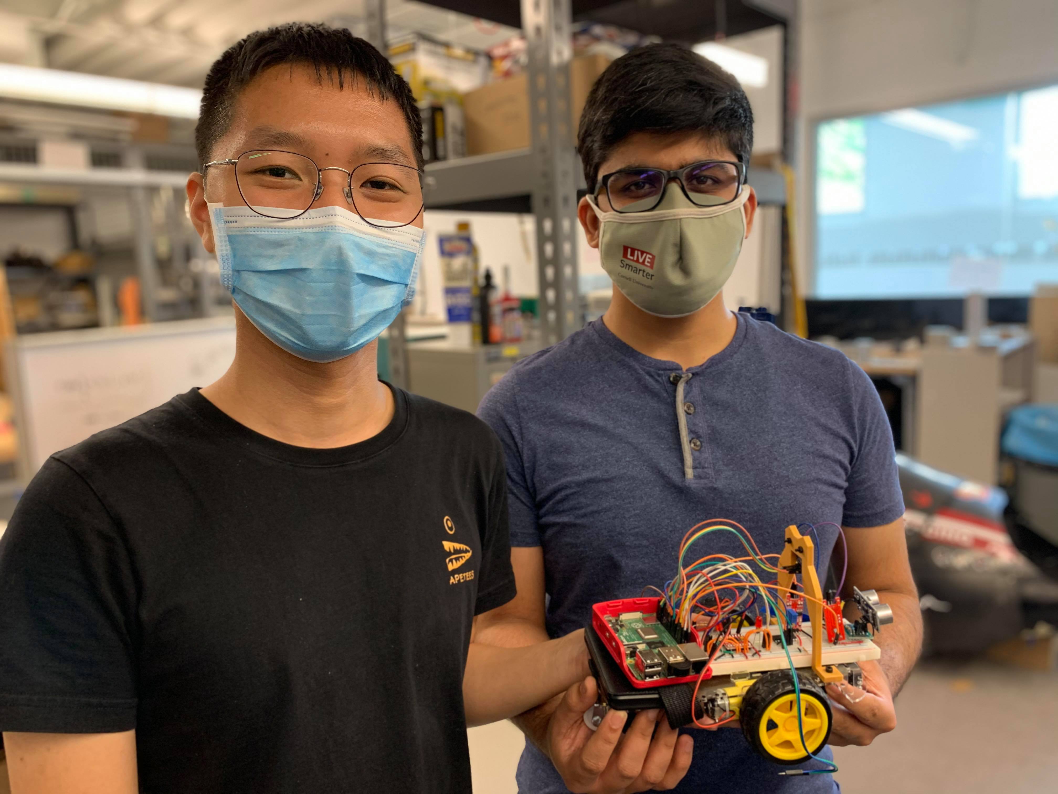
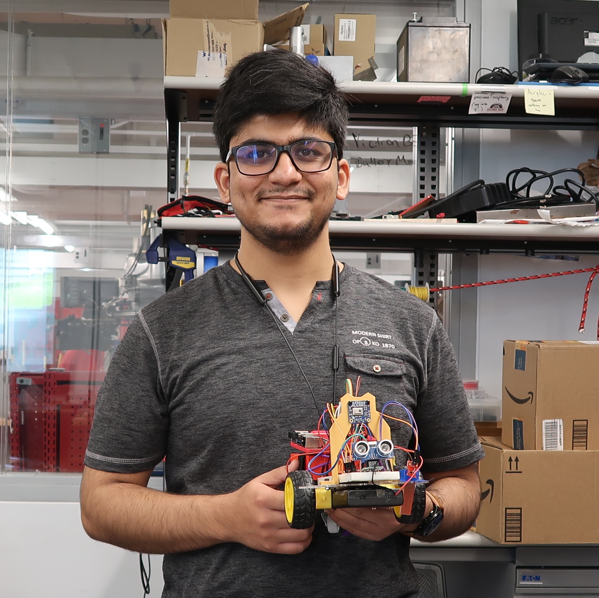
Project group picture
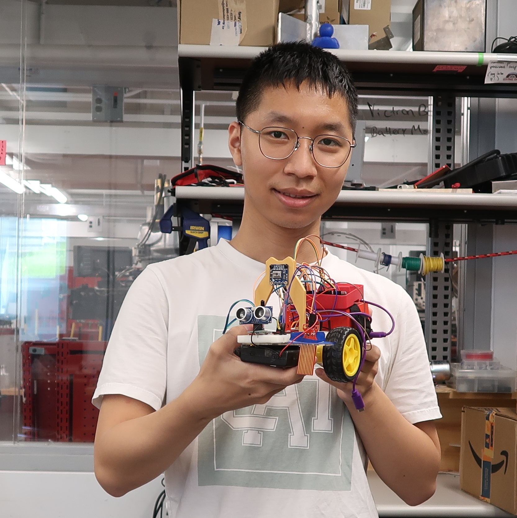
Robby Huang
lh479@cornell.edu
Handled hardware assembly, 3D printing, mapping, individual sensor testing and voice communication.
Parth Sarthi Sharma
pss242@cornell.edu
Handled TCP/IP communication, integration of sensors, motor control and android app development.
References
Processing (Software used for Android app development)Thermal Camera Input
Ultrasonic Sensor
Audio Input
ADC/SPI
ADC/SPI
ADC/SPI
Audio Output
Code Appendix
RobotRun.py
#Include all the libraries
import RPi.GPIO as GPIO #The GPIO library
import time #The time library
import sys #The sys library
import os #The os library
import pygame #The pygame library
from math import * #The math library
import numpy as np #The numpy library
import busio #The bus input output library
import board #The board library
import socket #The TCP IP socket library
from scipy.interpolate import griddata #The scipy library
from colour import Color #The colour library
import adafruit_amg88xx #The adafruit library for IR camera
import matplotlib.pyplot as plt #The matplotlib library

pygame.mixer.init() #Pygame mixer initialization for sounds
GPIO.setmode(GPIO.BCM) #Set BCM for GPIO

motor1PWMPin = 26 #PWM Pin for motor 1
motor1Pin1 = 5 #Pin 1 for motor 1
motor1Pin2 = 6 #Pin 2 for motor 1
motor2PWMPin = 16 #PWM Pin for motor 2
motor2Pin1 = 20 #Pin 1 for motor 2
motor2Pin2 = 21 #Pin 2 for motor 2

freq = 50 #Set PWM frequency to 50 Hz
dutyCycle = 50 #Set default duty cycle to 50%

CLK = 11 #Clock pin for SPI
MISO = 9 #MISO pin for SPI
MOSI = 10 #MOSI pin for SPI
CS = 17 #Chip Select pin for SPI

GPIO_TRIGGER = 18 #Trigger pin for ultrasonic
GPIO_ECHO = 24 #Echo pin for ultrasonic
GPIO_WATERLEVEL = 22 #Pin for water level sensor
GPIO_FLAME = 13 #Pin for flame level sensor
GPIO_ANTENNA = 27 #Pin for sensing radiation

GPIO.setup(motor1PWMPin, GPIO.OUT) #Setup motor 1 PWM pin as output
GPIO.setup(motor1Pin1, GPIO.OUT) #Setup motor 1 pin 1 as output
GPIO.setup(motor1Pin2, GPIO.OUT) #Setup motor 1 pin 2 as output
GPIO.setup(motor2PWMPin, GPIO.OUT) #Setup motor 2 PWM pin as output
GPIO.setup(motor2Pin1, GPIO.OUT) #Setup motor 2 pin 1 as output
GPIO.setup(motor2Pin2, GPIO.OUT) #Setup motor 2 pin 2 as output
GPIO.output(motor1Pin1, GPIO.LOW) #Set motor 1 pin 1 to be low
GPIO.output(motor1Pin2, GPIO.LOW) #Set motor 1 pin 2 to be low
GPIO.output(motor2Pin1, GPIO.LOW) #Set motor 2 pin 1 to be low
GPIO.output(motor2Pin2, GPIO.LOW) #Set motor 2 pin 2 to be low
motor1PWM = GPIO.PWM(motor1PWMPin, freq) #Initialize motor 1 PWM pin
motor2PWM = GPIO.PWM(motor2PWMPin, freq) #Initialize motor 2 PWM pin
motor1PWM.start(dutyCycle) #Start motor 1 PWM with the given duty cycle
motor2PWM.start(dutyCycle) #Start motor 2 PWM with the given duty cycle

GPIO.setup(GPIO_TRIGGER, GPIO.OUT) #Setup trigger pin as output
GPIO.setup(GPIO_ECHO, GPIO.IN) #Setup echo pin as input
GPIO.setup(GPIO_WATERLEVEL, GPIO.IN, pull_up_down = GPIO.PUD_DOWN) #Setup water level sensor pin as pulled down input
GPIO.setup(GPIO_FLAME, GPIO.IN, pull_up_down = GPIO.PUD_DOWN) #Setup flame sensor pin as pulled down input
GPIO.setup(GPIO_ANTENNA, GPIO.IN, pull_up_down = GPIO.PUD_DOWN) #Setup radiation sensor pin as pulled down input

fireVar = "No Fire" #Value for fire data to be sent
waterVar = "No Water" #Value for water data to be sent
radiationVar = "No Radiation" #Value for radiation data to be sent

MINTEMP = 26.0 #Minimum temperature to be detected
MAXTEMP = 32.0 #Maximum temperature to be detected
COLORDEPTH = 1024 #Colour depth to be 1024

distVar = 50 #Value for distance sensor
tempVar = 25 #Temperature data to be sent
distToStop = 15 #Distance threshold for the robot to stop

command = "STOP" #The command to control robot
prevCommand = "STOP" #The last received command

#Constraint function to limit the value
def constrain(val, min_val, max_val):
    return min(max_val, max(min_val, val))

#Function to fetch the distance from the ultrasonic sensor
def distance():
    GPIO.output(GPIO_TRIGGER, True)
    time.sleep(0.00001)
    GPIO.output(GPIO_TRIGGER, False)

    StartTime = time.time()
    StopTime = time.time()

    while GPIO.input(GPIO_ECHO) == 0:
        StartTime = time.time()

    while GPIO.input(GPIO_ECHO) == 1:
        StopTime = time.time()


    TimeElapsed = StopTime - StartTime
    distance = (TimeElapsed * 34300) / 2
    return distance

#Function to convert robot coordinates to global coordinates
def robot2global(pose, xyR):
    theta = pose[2]
    Trg = [[cos(theta), -sin(theta), pose[0]],
           [sin(theta), cos(theta), pose[1]],
           [0, 0, 1]]
    Trg = np.array(Trg)
    xyR.append(1)
    xyR = np.array(xyR)
    xyG = np.matmul(Trg, xyR.transpose())
    xyG = xyG[0:2]
    return xyG

#The mapping function
def startMap():
    global dutyCycle, motor1Pin1, motor1Pin2, motor2Pin1, motor2Pin2, motor1PWM, motor2PWM

    #Change the duty cycle to 100%
    motor1PWM.ChangeDutyCycle(100)
    motor2PWM.ChangeDutyCycle(100)

    distArray = []
    sensorOrigin = [10.8, 0]
    numPt = 200 #Number of points to be plotted
    theta = np.linspace(0, 2 * pi, numPt)

    #Fetch the distance for all the points
    for i in range(0, numPt):
        GPIO.output(motor1Pin1, GPIO.HIGH)
        GPIO.output(motor1Pin2, GPIO.LOW)
        GPIO.output(motor2Pin1, GPIO.HIGH)
        GPIO.output(motor2Pin2, GPIO.LOW)
        time.sleep(0.01)
        GPIO.output(motor1Pin1,GPIO.LOW)
        GPIO.output(motor1Pin2,GPIO.LOW)
        GPIO.output(motor2Pin1,GPIO.LOW)
        GPIO.output(motor2Pin2,GPIO.LOW)
        time.sleep(0.1)
        distArray.append(distance())
    xVal = []
    yVal = []
    for i in range(0, numPt):
        dpy = 0
        dpx = distArray[i] + sensorOrigin[0]
        depthPtG = robot2global([0,0,theta[i]], [dpx, dpy])
        xVal.append(depthPtG[0])
        yVal.append(depthPtG[1])
    plt.plot(0, 0, 'r+') #Plot the bot as a red +
    plt.plot(xVal, yVal, 'bo') #Plot the distances as blue circles
    plt.show() #Show the plot
    #Change the duty cycle back
    motor1PWM.ChangeDutyCycle(dutyCycle)
    motor2PWM.ChangeDutyCycle(dutyCycle)

#Function to map a value in a given range
def map_value(x, in_min, in_max, out_min, out_max):
    return (x - in_min) * (out_max - out_min) / (in_max - in_min) + out_min

#Setup the SPI pins
def setupSpiPins(clkPin, misoPin, mosiPin, csPin):
    GPIO.setup(clkPin, GPIO.OUT)
    GPIO.setup(misoPin, GPIO.IN)
    GPIO.setup(mosiPin, GPIO.OUT)
    GPIO.setup(csPin, GPIO.OUT)

#Read the ADC values using SPI
def readAdc(channel, clkPin, misoPin, mosiPin, csPin):
    if (channel < 0) or (channel > 7):
        print("Invalid ADC Channel number, must be between [0,7]")
        return -1

    GPIO.output(csPin, GPIO.HIGH)
    GPIO.output(csPin, GPIO.LOW)
    GPIO.output(clkPin, GPIO.HIGH)
    read_command = 0x18
    read_command |= channel

    sendBits(read_command, 5, clkPin, mosiPin)

    adcValue = recvBits(12, clkPin, misoPin)
    GPIO.output(csPin, GPIO.HIGH)
    return adcValue

#Send the bits
def sendBits(data, numBits, clkPin, mosiPin):
    data <<= (8 - numBits)

    for bit in range(numBits):
        if data & 0x80:
            GPIO.output(mosiPin, GPIO.HIGH)
        else:
            GPIO.output(mosiPin, GPIO.LOW)
        data <<= 1

        GPIO.output(clkPin, GPIO.HIGH)
        GPIO.output(clkPin, GPIO.LOW)

#Receive the data bits
def recvBits(numBits, clkPin, misoPin):
    retVal = 0

    for bit in range(numBits):
        GPIO.output(clkPin, GPIO.HIGH)
        GPIO.output(clkPin, GPIO.LOW)
        if GPIO.input(misoPin):
            retVal |= 0x1

        retVal <<= 1

    return (retVal/2)

#Callback function for water level sensor
def trigWater(channel):
    global waterVar
    if(waterVar == "Water"):
        waterVar = "No Water"
    else:
        waterVar = "Water"

#Callback function for fire sensor
def trigFire(channel):
    global fireVar
    if(fireVar == "Fire"):
        fireVar = "No Fire"
    else:
        fireVar = "Fire"

#Callback function for radiation sensor
def trigRadiation(channel):
    global radiationVar, fireVar, waterVar
    radiationVar = "Radiation"
    if(fireVar == "Fire"):
        fireVar = "No Fire"
    else:
        fireVar = "Fire"
    if(waterVar == "Water"):
        waterVar = "No Water"
    else:
        waterVar = "Water"

i2c_bus = busio.I2C(board.SCL, board.SDA) #Setup the I2C bus
sensor = adafruit_amg88xx.AMG88XX(i2c_bus) #Setup the IR sensor using I2C

points = [(floor(ix / 8), (ix % 8)) for ix in range(0, 64)] #Points for the IR sensor
grid_x, grid_y = np.mgrid[0:7:32j, 0:7:32j] #Create the grid

blue = Color("indigo") #The colour blue
colors = list(blue.range_to(Color("red"), COLORDEPTH)) #The colours list
colors = [(int(c.red * 255), int(c.green * 255), int(c.blue * 255)) for c in colors]

time.sleep(0.1) #Do not remove. Lets sensor initialize

GPIO.add_event_detect(GPIO_WATERLEVEL, GPIO.BOTH, callback = trigWater, bouncetime = 300) #The event detection for water level sensor
GPIO.add_event_detect(GPIO_FLAME, GPIO.BOTH, callback = trigFire, bouncetime = 300) #The event detection for fire sensor
GPIO.add_event_detect(GPIO_ANTENNA, GPIO.BOTH, callback = trigRadiation, bouncetime = 300) #The event detection for radiation detection sensor

timeStamp = time.time() #The start time flag

if __name__ == '__main__':
    try:
        setupSpiPins(CLK, MISO, MOSI, CS) #Call the SPI setup function
        HOST = '10.49.32.252' #The server IP address (RaspberryPi in this case)
        PORT = 8000 #The port for the socket
        print(socket.gethostname()) #Print the hostname
        s = socket.socket(socket.AF_INET, socket.SOCK_STREAM) #Start the socket
        s.setsockopt(socket.SOL_SOCKET, socket.SO_REUSEADDR, 1) #Configure the socket
        s.bind((HOST, PORT)) #Bind the socket
        s.listen(5) #Listen for clients
        conn, addr = s.accept() #Accept the connection
        print(addr) #Print the address of the connected clients

        connected = False #The connected flag

        while True: #While infinity
            connected = False #Default the connected flag to false
            pixels = [] #The pixels array
            for row in sensor.pixels:
                pixels = pixels + row
            pixels = [map_value(p, MINTEMP, MAXTEMP, 0, COLORDEPTH - 1) for p in pixels]

            bicubic = griddata(points, pixels, (grid_x, grid_y), method="cubic")

            data = "" #The data to be transmitted
            for pixel in pixels: #Append the pixels to the data to be transmitted with a ',' delimiter
                data = data + str(pixel) + ","
            data = data + ";"  #Append the ';' delimiter
            for bi in bicubic: #Append the bicubic to the data to be transmitted with a ',' delimiter
                for b in bi:
                    data = data + str(b) + ","
            data = data + ";" #Append the ';' delimiter
            for color in colors: #Append the color to the data to be transmitted with a ':' delimiter
                data = data + str(color) + ":"
            data = data + ";" #Append the ';' delimiter
            data = data + waterVar + "," + fireVar + "," + radiationVar + "," + str(tempVar) + "," + str(distVar) + ";" #Append the sensor data to the data to be transmitted with a ',' delimiter
            try:
                conn.send((data + "\n").encode()) #Encode the data and transmit over TCP/IP connection
                connected = True #If no error is thrown, mark the connected flag as true
            except: #If an error is thrown
                #Try reconnecting
                s = socket.socket(socket.AF_INET, socket.SOCK_STREAM)
                s.setsockopt(socket.SOL_SOCKET, socket.SO_REUSEADDR, 1)
                s.bind((HOST, PORT))
                s.listen(5)
                conn, addr = s.accept()
                print(addr)
                connected = True #Mark the connected flag as true
            if connected: #If connected
                try:
                    command = conn.recv(1024) #Receive the data from clients
                    command = command.decode().strip() #If the data is received, decode the command, then strip all the whitespaces
                except: #If the data reception fails
                    connected = False #Mark the connected flag as false
            if(command != prevCommand): #If the command has changed
                print(command) #Print the new command

            if(command == "STOP" and prevCommand != "STOP"): #If the new command is STOP
                GPIO.output(motor1Pin1, GPIO.LOW)
                GPIO.output(motor1Pin2, GPIO.LOW)
                GPIO.output(motor2Pin1, GPIO.LOW)
                GPIO.output(motor2Pin2, GPIO.LOW)
            elif(command == "UP" and prevCommand != "UP"): #If the new command is UP
                if distVar > distToStop: #If the distance is greater than the threshold value
                    GPIO.output(motor1Pin1, GPIO.LOW)
                    GPIO.output(motor1Pin2, GPIO.HIGH)
                    GPIO.output(motor2Pin1, GPIO.HIGH)
                    GPIO.output(motor2Pin2, GPIO.LOW)
                else:
                    GPIO.output(motor1Pin1, GPIO.LOW)
                    GPIO.output(motor1Pin2, GPIO.LOW)
                    GPIO.output(motor2Pin1, GPIO.LOW)
                    GPIO.output(motor2Pin2, GPIO.LOW)
            elif(command == "DOWN" and prevCommand != "DOWN"): #If the new command is DOWN
                GPIO.output(motor1Pin1, GPIO.HIGH)
                GPIO.output(motor1Pin2, GPIO.LOW)
                GPIO.output(motor2Pin1, GPIO.LOW)
                GPIO.output(motor2Pin2, GPIO.HIGH)
            elif(command == "LEFT" and prevCommand != "LEFT"): #If the new command is LEFT
                GPIO.output(motor1Pin1, GPIO.HIGH)
                GPIO.output(motor1Pin2, GPIO.LOW)
                GPIO.output(motor2Pin1, GPIO.HIGH)
                GPIO.output(motor2Pin2, GPIO.LOW)
            elif(command == "RIGHT" and prevCommand != "RIGHT"): #If the new command is RIGHT
                GPIO.output(motor1Pin1, GPIO.LOW)
                GPIO.output(motor1Pin2, GPIO.HIGH)
                GPIO.output(motor2Pin1, GPIO.LOW)
                GPIO.output(motor2Pin2, GPIO.HIGH)
            elif(command == "HELP" and prevCommand != "HELP"): #If the new command is HELP
                GPIO.output(motor1Pin1, GPIO.LOW)
                GPIO.output(motor1Pin2, GPIO.LOW)
                GPIO.output(motor2Pin1, GPIO.LOW)
                GPIO.output(motor2Pin2, GPIO.LOW)
                pygame.mixer.music.load("help.wav") #Load the audio file
                pygame.mixer.music.play() #Play the audio file
            elif(command == "RECORD" and prevCommand != "RECORD"): #If the new command is RECORD
                GPIO.output(motor1Pin1, GPIO.LOW)
                GPIO.output(motor1Pin2, GPIO.LOW)
                GPIO.output(motor2Pin1, GPIO.LOW)
                GPIO.output(motor2Pin2, GPIO.LOW)
                pygame.mixer.music.load("record.wav") #Load the audio file
                pygame.mixer.music.play() #Play the audio file
                while(pygame.mixer.music.get_busy() == True): #While the audio files is being played
                    pass #Pass
                os.system('arecord --device=hw:2,0 -d 5 --format S16_LE --rate 44100 -c1 victimRecord.wav -V mono') #System command to record from microphone
            elif(command == "PLAY" and prevCommand != "PLAY"): #If the new command is PLAY
                GPIO.output(motor1Pin1, GPIO.LOW)
                GPIO.output(motor1Pin2, GPIO.LOW)
                GPIO.output(motor2Pin1, GPIO.LOW)
                GPIO.output(motor2Pin2, GPIO.LOW)
                pygame.mixer.music.load("victimRecord.wav") #Load the audio file
                pygame.mixer.music.play() #Play the audio file
            elif(command == "MAP" and prevCommand != "MAP"): #If the new command is MAP
                startMap() #Start mapping
            elif(command == "INC"): #If the new command is INC
                if dutyCycle < 100: #If duty cycle is less than 100
                    dutyCycle += 1 #Increment duty cycle
                    #Change duty cycle
                    motor1PWM.ChangeDutyCycle(dutyCycle)
                    motor2PWM.ChangeDutyCycle(dutyCycle)
            elif(command == "DEC"): #If the new command is DEC
                if dutyCycle > 40: #If duty cycle is greater than 40
                    dutyCycle -= 1 #Decrement duty cycle
                    #Change duty cycle
                    motor1PWM.ChangeDutyCycle(dutyCycle)
                    motor2PWM.ChangeDutyCycle(dutyCycle)

            prevCommand = command #Change previous command

            if(time.time() - timeStamp > 0.01): #If the time elapsed is 1 millisecond
                adc = readAdc(0, CLK, MISO, MOSI, CS) #Read ADC
                try:
                    tempVar = 10 * log(10000 * (1024 / (adc / 3.3) - 1), 10) - 10 #Scale the temperature
                    tempVar = round(tempVar, 3) #Round the temperature to 3 digits
                except: #If it throws an error
                    pass
                distVar = round(distance(), 3) #Fetch the distance and round it to 3 digits
                if(distVar < distToStop): #If the distance is less tha  threshold distance
                    print("Dist Stopping..") #Print "Dist Stopping.."
                timeStamp = time.time() #Update the timestamp
    except KeyboardInterrupt: #If interrupted from keyboard
        motor1PWM.stop() #Stop the motor 1 PWM
        motor2PWM.stop() #Stop the motor 2 PWM
        GPIO.cleanup() #Cleanup GPIO
        print("Exiting...") #Print "Exiting..."
        sys.exit(0) #Exit the program
MainCode.pde
//Import libraries for TCP/IP
import java.net.*;
import java.io.*;

ArrayList <Button> buttons = new ArrayList<Button>(); //Arraylist for buttons

String hostname = "10.49.74.93"; //IP address of the server to connect to
int port = 8000; //Port for the socket to connect to

int buttonSize = 150; //The default button size
String command = "STOP"; //The default command to send
boolean commLock = false; //Flag for communication lock

float pixelVals[] = new float[64]; //Pixel array
float bicubics[][] = new float[32][32]; //Bicubics array
color colorArray[] = new color[1024]; //Colour array

InputStreamReader reader; //Input stream reader
PrintWriter writer; //Output print writer

void setup(){ //The setup function
  fullScreen(); //Setup screen to be full screen
  orientation(LANDSCAPE); //Set the orientation to be landscape
  frameRate(60); //Set the frame rate to be 60 fps
  try{ //Try
    Socket socket = new Socket(hostname, port); //Connect to the socket
    InputStream input = socket.getInputStream(); //Create the input stream to read incoming data
    OutputStream output = socket.getOutputStream(); //Create the output stream to write outgoing data
    reader = new InputStreamReader(input); //Attach the reader to the input stream
    writer = new PrintWriter(output, true); //Attach the writer to the output stream
  }
  catch (Exception ex) { //Catch exception
    textSize(20); //Set the text size to be 20
    fill(0); //Change colour to black
    text(ex.getMessage(), 5, 20); //Display the error message
    println(ex.getMessage()); //Print the error message
  }

  addButtons(); //Add all the buttons
}

void draw(){ //The draw function
  background(255); //Fill screen with white colour

  try{ //Try
    int character; //Character to be read
    StringBuilder data = new StringBuilder(); //String builder
    character = reader.read(); //Rad the character
    while ((character != 10) && ((character != -1))) { //Until the character is new line or null
      data.append((char) character); //Append the character to the string builder
      character = reader.read(); //Read the next character
    }
    data.append("\n"); //Append a new line character
    String receivedString = data.toString(); //Convert to string
    String dataArrays[] = receivedString.split(";"); //Split the received string around the ";" character and store the resultant substrings into an array
    String pixelArray[] = dataArrays[0].split(","); //Split the pixel array around the "," character
    String bicubicArray[] = dataArrays[1].split(","); //Split the bicubic array around the "," character
    String colArray[] = dataArrays[2].split(":"); //Split the colour array around the ":" character
    String sensorArray[] = dataArrays[3].split(","); //Split the sensor array around the "," character

    fill(0); //Make the colour black
    textSize(40); //Set the text size to be 40
    //Print the sensor strings on the screen
    text("Water: ", 40, 100);
    text("Fire: ", 40, 150);
    text("Radiation: ", 40, 200);
    text("Temperature: ", 40, 250);
    text("Distance: ", 40, 300);
    //Print the sensor values on the screen
    for(int i = 0; i < sensorArray.length; i++){
      text(sensorArray[i], 305, 100 + i * 50);
    }
    //Get pixel values
    for(int i = 0; i < pixelVals.length; i++){
      pixelVals[i] = Float.parseFloat(pixelArray[i]);
    }
    //Get bicubic values
    for(int i = 0; i < bicubics.length; i++){
      for(int j = 0; j < bicubics[i].length; j++){
        bicubics[i][j] = Float.parseFloat(bicubicArray[i * bicubics.length + j]);
      }
    }
    //Get colour values
    for(int i = 0; i < colorArray.length; i++){
      String redGreenBlue[] = colArray[i].split(",");
      colorArray[i] = color(Integer.parseInt(redGreenBlue[0].substring(1).trim()), Integer.parseInt(redGreenBlue[1].trim()), Integer.parseInt(redGreenBlue[2].substring(0, redGreenBlue[2].length() - 1).trim()));
    }
    //Do the colour printing magic to create the image in the screen
    for(int i = 0; i < bicubics.length; i++){
      for(int j = 0; j < bicubics[i].length; j++){
        float pixelVal = bicubics[i][j];
        fill(colorArray[myConstrain((int) pixelVal, 0, 1024 - 1)]);
        rect((width / 2) - (height / 2) + ((height / 30) * i), (height / 30) * j, (height / 30), (height / 30));
      }
    }
  }
  catch (Exception ex) { //Catch exception
    textSize(20); //Set the text size to be 20
    fill(0); //Change colour to black
    text("I/O error: " + ex.getMessage(), 5, 20); //Display the error message
    println(ex.getMessage()); //Print the error message
    try{ //Try
      Socket socket = new Socket(hostname, port); //Connect to the socket
      InputStream input = socket.getInputStream(); //Create the input stream to read incoming data
      OutputStream output = socket.getOutputStream(); //Create the output stream to write outgoing data
      reader = new InputStreamReader(input); //Attach the reader to the input stream
      writer = new PrintWriter(output, true); //Attach the writer to the output stream
    }
    catch (Exception ex1) { //Catch
    }
  }
  if(!commLock){ //If the command has not been locked
    command = "STOP"; //Make the default command ""STOP
  }
  try{ //Try
    writer.println(command); //Send the command over to the TCP/IP socket
  }
  catch (Exception ex) { //Catch
  }
  for(Button b: buttons){ //For all the buttons
    b.drawButton(); //Draw the button
  }
}

int myConstrain(int val, int minVal, int maxVal){ //Constraint function
  return min(maxVal, max(minVal, val));
}
Button.pde
class Button{ //The button class
  String text; //The text to be displayed
  int x, y; //x and y coordinates of the button
  int bLength, bHeight; //The button length and button height

  Button(int xCor, int yCor, String bText, int bl, int bh){ //Constructor 1
    x = xCor;
    y = yCor;
    text = bText;
    bLength = bl;
    bHeight = bh;

  }
  Button(int xCor, int yCor, String bText){ //Constructor 2
    x = xCor;
    y = yCor;
    text = bText;
    bLength = buttonSize;
    bHeight = buttonSize;
  }

  void drawButton(){ //Draw button
    fill(127); //Fill with grey
    stroke(0); //Make border black
    strokeWeight(3); //Make border width 3
    rect(x, y, bLength, bHeight); //Draw rectangle
    strokeWeight(1); //Make border width 1

    fill(0); //Fill with black
    textSize(40); //Make text size 40
    text(text, x + (bLength / 2) - (textWidth(text) / 2), y + (bHeight / 2) + (textAscent() / 2)); //Print button text
  }
}
addButtonFunc.pde
void addButtons(){ //The function to add buttons
  buttons.add(new Button((width / 4) - (height / 4) - (buttonSize / 2), 650, "UP"));
  buttons.add(new Button((width / 4) - (height / 4) - (buttonSize / 2), 850, "DOWN"));
  buttons.add(new Button((width / 2) + (height / 2) + (height / 15) + (((width / 2) - (height / 2)) / 4) - (buttonSize / 2), 850, "LEFT"));
  buttons.add(new Button((width / 2) + (height / 2) + (((width / 2) + (height / 2)) / 4) - (buttonSize / 2), 850, "RIGHT"));

  buttons.add(new Button((width / 4) - (height / 4) - (3 * buttonSize / 2), 450, "INC"));
  buttons.add(new Button((width / 4) - (height / 4) + (buttonSize / 2), 450, "DEC"));

  buttons.add(new Button((width / 2) + (height / 2) + (height / 15) + (((width / 2) - (height / 2)) / 4) - (buttonSize / 2), 50, "HELP", 2 * buttonSize + (buttonSize / 5), buttonSize));
  buttons.add(new Button((width / 2) + (height / 2) + (height / 15) + (((width / 2) - (height / 2)) / 4) - (buttonSize / 2), 250, "RECORD", 2 * buttonSize + (buttonSize / 5), buttonSize));
  buttons.add(new Button((width / 2) + (height / 2) + (height / 15) + (((width / 2) - (height / 2)) / 4) - (buttonSize / 2), 450, "PLAY", 2 * buttonSize + (buttonSize / 5), buttonSize));
  buttons.add(new Button((width / 2) + (height / 2) + (height / 15) + (((width / 2) - (height / 2)) / 4) - (buttonSize / 2), 650, "MAP", 2 * buttonSize + (buttonSize / 5), buttonSize));
}
mouseFunc.pde
void mousePressed(){ //The mouse pressed function
  for(Button b: buttons){ //For all buttons
    if(mouseX > b.x && mouseX < b.x + b.bLength && mouseY > b.y && mouseY < b.y + b.bHeight){ //If this pressed
      commLock = true; //Lock the command flag
      command = b.text; //Change the command to button
      break; //Break out of the loop
    }
  }
}

void mouseReleased(){ //The mouse released function
  commLock = false; //Unlock the command flag
}