Mechanical Aimbot
Rohan Agarwal (ra462), Kenneth Mao (km633), Rishi Singhal (rs872)
May 21st, 2020
Demo Video
Check out our mechanical aimbot here!
Introduction
In many games, cheaters use software aimbots to gain an unfair advantage against fellow players. An aimbot is a piece of software that provides virtual inputs to turn the player to face the enemy. Our project was to create a hardware based aimbot which monitors the game with a camera and moves a wireless mouse to target a creeper in Minecraft. The user would be able to navigate in the game, while the aimbot keeps the creeper in the center of the display. This hardware aimbot would not require the user to install any software, and could function on any monitor. The mechanical aimbot is composed of two parts: (1) a base station consisting of a Raspberry Pi, RPi camera, breadboard with cables and resistors, 6V AA battery enclosure, and acrylic sheets; and (2) a mouse carrier consisting of four Parallax servos, four omni-directional wheels, acrylic sheets, and packing foam. We needed four omni-directional wheels and servos placed perpendicularly to each other inorder to mimic mouse movement. With only two servos, horizontal movement of the robot would require a change of heading and then movement in the new direction, which is unlike real mouse movement. Long cables are required to connect the base station to the mouse carrier, as the camera needs to remain stationary and viewing the monitor while the mouse carrier moves the wireless mouse. The RPi uses OpenCV to do image processing that detects a creeper in the image taken by the RPi camera, and then sends commands to the servos to move the mouse carrier so that the center of the screen is the center of the creeper. Once the creeper was in the center of the display and correspondingly, the center of the image taken by the RPi camera, the RPi would indicate that the target is in the center of the display and the user could fire.
The mechanical aimbot is composed of two parts: (1) a base station consisting of a Raspberry Pi, RPi camera, breadboard with cables and resistors, 6V AA battery enclosure, and acrylic sheets; and (2) a mouse carrier consisting of four Parallax servos, four omni-directional wheels, acrylic sheets, and packing foam. We needed four omni-directional wheels and servos placed perpendicularly to each other inorder to mimic mouse movement. With only two servos, horizontal movement would require a change of heading (i.e. rotation of the robot without moving the mouse) and then movement in the new direction, which is unlike real mouse movement. Long cables are required to connect the base station to the mouse carrier, as the camera needs to remain stationary and viewing the monitor while the mouse carrier moves the wireless mouse. The RPi uses OpenCV to do image processing that detects a creeper in the image taken by the RPi camera, and then sends commands to the servos to move the mouse carrier so that the center of the screen is the center of the creeper. Once the creeper was in the center of the display and correspondingly, the center of the image taken by the RPi camera, the RPi would indicate that the target is in the center of the display and the user could fire.
Objective
The objective of the project was to create a system that could move a mouse such that the target (in our case, a creeper in Minecraft) was in the center of the display. The Raspberry Pi would use its camera to take a picture, use openCV to accurately recognize a creeper, and then set the appropriate PWM values to the appropriate motors to move the mouse until the creeper is in the center of the display. This project required an understanding in computer vision, image processing, PWM servo control, and mechanical design.
Design and Testing
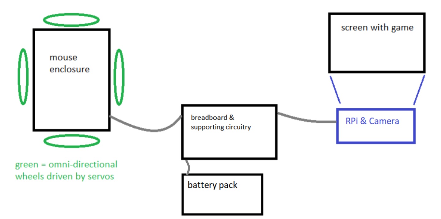
Figure 1: Overall electro-mechanical system
The hardware design of our mechanical aimbot consists of a mouse carrier with four omni wheels and four servos, a Raspberry Pi, and a Raspberry Pi camera (Figure 1). The first system we designed was the mouse carrier (Figure 2). The original plan was to 3D print an enclosure that carefully matched the shape of the mouse. However, due to the COVID-19 outbreak, we needed to adapt and improvise our design. Another factor that increased the difficulty of creating the mouse carrier was the lack of tools. With only a drill, hand saw, and a sander, it was difficult to cut and drill accurately. This required us to simplify the platform of the mouse carrier to two acrylic sheet rectangles placed over each other. The two sheets were glued together to form a cross. Because the sheets of acrylic are placed on top of each other, there is a significant height difference. Thus, to ensure that all the wheels are mounted at the same level, we needed to create spacers for the servo mount brackets (see Figure 3).
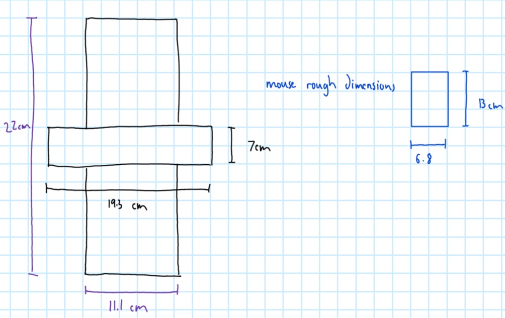
Figure 2: Dimensions of mouse carrier
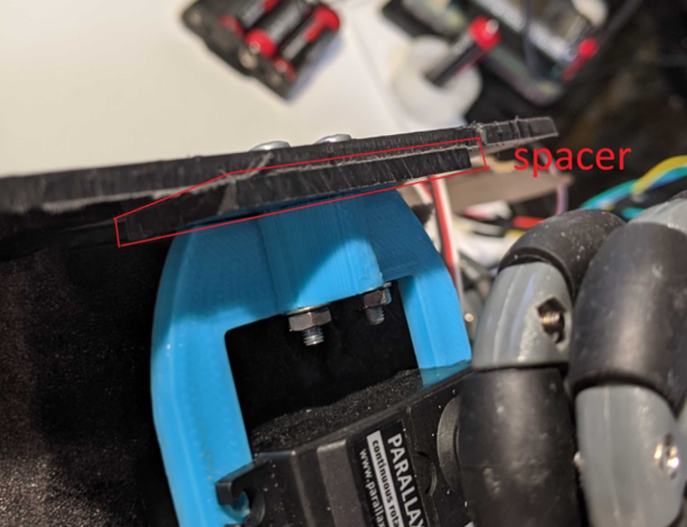
Figure 3: Acrylic spacer for servo mounting
One particular challenge of manufacturing was drilling the mounting holes for the servo brackets. If the spacing between the holes were not accurate, the bracket would not fit. If the pair of mounting holes were not parallel to the mounting holes on the opposite side, the mouse carrier wouldn’t be able to travel in a straight line. In order to overcome this issue, we first created a pilot hole with a drill bit that was significantly smaller than the final hole. Once we were sure that the holes were in the correct position, we switched to the full size drill bit. After the appropriate pieces were cut with a hand saw, we sanded down the sharp edges. Once we had the platform of the mouse carrier we attached the servo mounts to it.
The next hurdle we faced involved attaching the omni directional wheel to the parallax servo. The through hole of the omni wheel is significantly larger than the outer diameter of the servo axle. Thus, in order to attach the omni-wheels to the servos, we drilled a hole the size of the servo axle into a plastic spacer. We then placed the plastic spacer into the omni wheel and press-fitted the plastic spacer onto the servo axle. Furthermore, we used the screws for the wheels from Lab 3 to secure the plastic spacer to the servo.
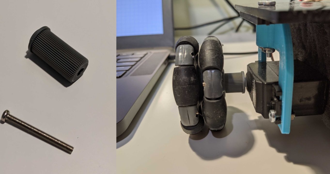
Figure 4: Adapter for omni wheel to servo
Four servos and omni wheels placed perpendicularly to each other are required to accurately mimic mouse movement. If a person using a mouse changes the heading of the mouse and moves it forward and backwards, this would only result in the mouse cursor moving up and down on the display. Thus, to enable horizontal movement, we need an extra pair of servos. Omni directional wheels allow for servos to drive movement in one direction, but move freely in the perpendicular direction.
Once the mouse carrier was completed, we needed to splice together long wires. This was required so the mouse carrier can move independently of the camera. While on paper bluetooth sounds like a viable method to send the PWM signals to the servos, the delay makes it unsuitable for a latency sensitive application like this. One issue we kept running into (literally) was that wires would get caught in the wheels. In order to mitigate this issue, we first attempted a stand for the wires to run over (this is seen highlighted in red in Figure 5). However, we found out that simply extending the platform with cardboard was a more effective solution.
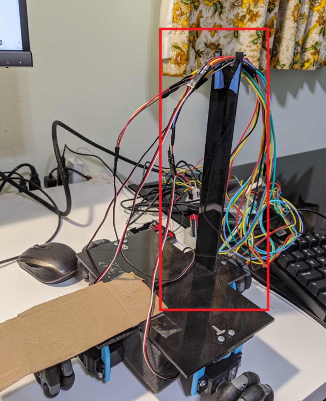
Figure 5: Wire stand
The servos we used were Parallax Standard Servo (#900-00005). These servos can be run off of Raspberry Pi’s GPIO pins. We placed a 1K resistor between the GPIO pin from the RPi and the PWM signal of the servo to protect the pin from being over-volted. In order to power the servos, we used the four double A battery enclosure to provide 6V.

Figure 6: GPIO PWM Circuitry
One final issue we faced was securing the camera. In order to get repeatable results, we created a simple L stand that velcroed the RPi in place and taped the camera to a specific height on the stand. While not ideal, taping it to the stand allowed us to easily adjust the height of the camera (see Figure 7).
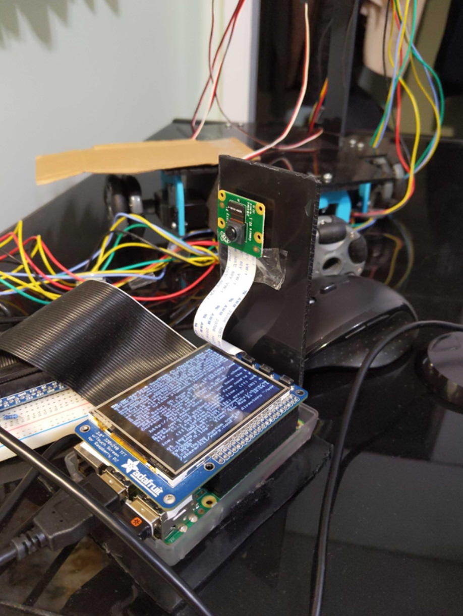
Figure 7: Camera Stand
From the software side of things, we divided the code design into 3 stages: image preprocessing, center point extraction, and servo interfacing. For specific details on how all of these stages are implemented, see the Code Appendix.
For the image preprocessing, we first took an image and resized it to a smaller resolution using the resize() function of the OpenCV library so that there was less information to process at once. Once this was done, we needed to figure out a way to isolate all the green pixels in an image (since we constrained our classification to finding creepers in a controlled Minecraft environment, this was a simple yet effective design choice). To do this, we used OpenCV’s bitwise_and command to create a mask for our image containing the pixels that are within the specified range of BGR pixel values, in our case specific shades of green. Determining this range required various iterations to changing values on the color wheel until we found a reliable range that didn’t give outlier errors, but eventually we were able to transform our taken camera image as shown below.
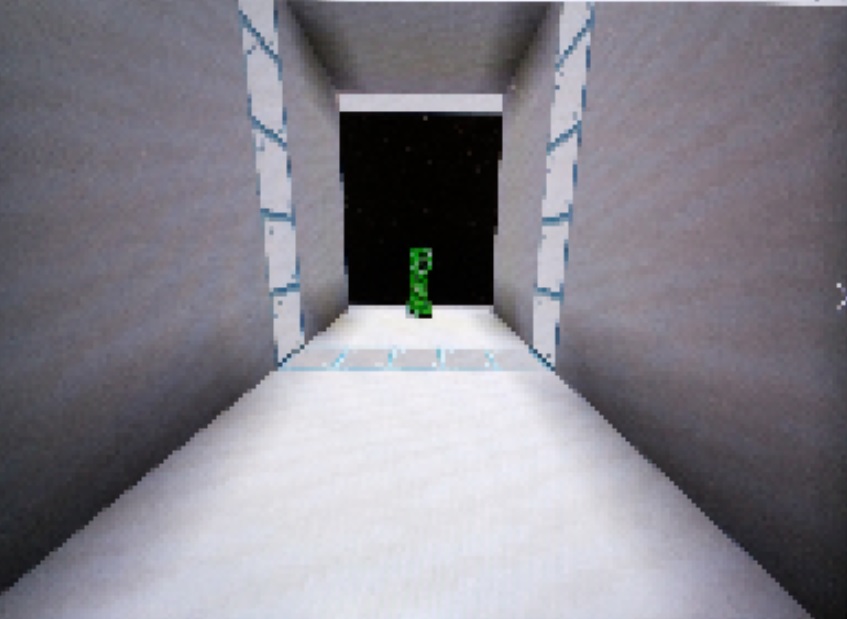

Figure 8: Creeper Processing Before and After
For determining the center point to target for the creeper, we had to find the nonzero pixel values of our masked image (i.e. the image you see above on the right). Once we have all the green pixels, we define a bounding box on our target by simply taking the minimum and maximum x and y values from our masked pixel array. We then average these lower-left and upper-right coordinates to find the center point of our target, scale the resolution back up to that of the original PiCamera image, and then calculate the pixel difference between the true center of the image and the calculated target center. By testing this code on various different images with the creeper located at different positions, and printing onto our terminal screen the calculated target point, we were able to get an accurate impression of whether this code worked or not.
The final key piece of software that was necessary was Python code that interfaced with the servos on our robot. This code involved using the RPi.GPIO library, which we used in Lab 3 of the class. Similar to what we did in Lab 3, we had to set up and instantiate a PWM instance for each servo, and then write a frequency and duty cycle to a particular instance to make that motor drive in a particular direction at a particular speed. Using the Parallax Servo Datasheet (see References) was helpful in determining the range of values to write. As a fun way to test the servo functionality, we made our robot move along to the beat of Billie Eilish’s famous song, “bad guy.” You can see the video here:
Issues and Solutions
There were numerous problems that we faced throughout the design of this project. One issue we had was attaching the omni directional wheel to the parallax servo. We resolved the issue by drilling a hole in a plastic spacer and press fitting the spacer onto the wheel and the spacer onto the servo. Another issue was the wires getting tangled in the wheels. To mitigate this we simply used cardboard to extend the mouse carrier’s platform longer. One final mechanical issue was keeping the camera stable. This was solved by creating a simple “L” shaped stand and taping the camera to the stand. Resolutions to these issues are explained more thoroughly in the Design and Testing section.
Many of our other issues were faced when integrating all parts of our system together. For one, when we tried to integrate taking a picture with the PiCamera into our Python code, we found that using the “raspistill” command to do so took too long. This is because raspistill only turns on the camera long enough to take a picture, and then turns it off again, meaning each time we called the command we needed to wait for the camera to restart. To mitigate this latency, we tried to manually keep a camera stream going and then extract frames from that stream to grab a picture (see References link for more information). Doing so, however, took up all of the CPU power of the Raspberry Pi core we were using, making it impossible to run other applications alongside it. As such, we shifted to using the PiCamera Python library, which was a library that was already optimized to keep a camera stream going and capture a frame from it for processing. This method had a low latency, which is why we were able to work with it for the rest of the project.
Another issue we found when doing system integration and testing was that if our camera detected no potential targets, the aimbot would keep moving in the same direction. This was an edge case that was dangerous for our setup, since our aimbot could roll off of our table. As such, we had to add a conditional corner case check for this situation, and turn off the motors before taking another image and starting the processing again.
Arguably the most number of issues we faced came when calibrating our system to function for our particular demo. We had an issue making our system work with the lowest mouse sensitivity on Minecraft, since our system still managed to overshoot by the time it calculated a new target center. This resulted in oscillation, which was suboptimal for performance. We initially tried to fix this issue by lowering our PWM settings such that the robot moved slower, though this led to the entire system stuttering and rotating as opposed to moving linearly. As such, we eventually had to stop the motors halfway between an iteration of our loop and wait to restart again once we calculated a new target.
One final issue we had when calibrating the aimbot to the game was the fact that tuning our tolerance parameters was very finicky. Since we did not have a concrete understanding of the game’s internal physics engine, we had to guess and check various tolerance values to see what worked best. This was made even more difficult due to the fact that this is a dynamic system, meaning the camera could slightly vibrate and lead to a one-off poor reading. We tried to resolve and smoothing out the data by averaging the calculations across multiple successively-taken images, but this resulted in too much latency in one iteration of the loop. As such, we had to spend quite a lot of time tuning our tolerance thresholds until we found values that seemed to reliably work.
One underlying issue to note among this entire design process was the need to adapt to a remote workflow due to the ongoing COVID-19 pandemic. Since not all of us had access to the hardware, it was imperative to coordinate times for all of us to meet, which was difficult at times. We used reverse-SSH to all be able to access the Pi and code, but the connection kept dropping after several hours in use, making the overall work process slightly frustrating. Nevertheless, we managed to persevere and pull through.
Results and Conclusions
In the end, everything performed as planned for our project, from a user perspective. We were able to successfully capture an image of a Minecraft game screen, process the image to detect the location of a creeper, translate the pixel positions of the creeper to motor movements, and move the robot until the creeper was at the center of the computer screen (as seen by the PiCamera). As such, we were able to meet all of the goals we outlined in our project description, specifically tuned to a fixed mouse sensitivity and the detection of creepers in a game of Minecraft. We were not able to meet our stretch goal of clicking the mouse after moving it to the desired position due to time and hardware constraints.
Future Work
Due to time limitations, there were some alternative methods of performing tasks in our project that we didn’t have the chance to fully explore. As such, there are still various things we can do to make our project more efficient. For one, our current aimbot implementation uses the RPi.GPIO library, which is a software-based PWM library for the Raspberry Pi that uses software timers. For better accuracy and performance, the pigpio library could have been used to interface the Raspberry Pi with the motors, since this library uses a hardware timer to set its PWM values.
One other thing we could explore to improve performance of our aimbot is assigning certain functions to run on different cores using Linux’s taskset command and isolating one of the four Raspberry Pi CPU cores. This would have been useful for the PiCamera stream in particular, since then we could have one core dedicated to taking in camera input and have another core simply grab a frame from the stream to use in our processing algorithm.
To accomplish our stretch goal, we could have implemented another servo attached to a piece of cut acrylic to act as our mouse clicker. This would have accomplished full system automation as the user would not even have to press the spacebar to attack the creeper. The Raspberry Pi would simply send servo commands rather than printing to the console window that the creeper has been centered on the screen.
One final thing we could improve in our final project is our image preprocessing algorithm. We currently do a bitwise and based on a color mask, which limits our code’s functionality to areas that don’t have green in the background and to situations with only individual creepers present. To make our code more robust, we could train a tensorflow model to detect creepers in any environment, and use that model for determining the center point coordinates to target.
Budget
Our budget for this project was $100, and does not include parts given to us in the Raspberry Pi system kit received from the class. A list of materials used, as well as prices for any extra materials not in the kit that needed to be purchased, is shown below.
1 x Raspberry Pi 3B+ Free (included in RPi system kit)
1 x Raspberry Pi Case Free (included in RPi system kit)
1 x 16GB SD Card Free (included in RPi system kit)
1 x Raspberry Pi Camera Module Free (included in RPi system kit)
2 x Parallax Continuous Rotation Servos Free (included in RPi system kit)
Robot chassis + Wheels + Acrylic Free (included in RPi system kit)
1 x Battery Bank Free (included in RPi system kit)
4 x AA Batteries + Holder Free (included in RPi system kit)
2 x Extra Parallax Continuous Rotation Servos $25.18
4 x Omniwheels $33.32
Total Additional Cost: $58.50
As we can see, we were able to complete this project under budget.
References
This Parallax Servo datasheet was used to help us set the servo parameters we needed in order to drive our aimbot: https://www.parallax.com/sites/default/files/downloads/900-00005-Standard-Servo-Product-Documentation-v2.2.pdf
This link was an initial reference used to try to get quicker pictures from the PiCamera in our Python code: https://www.raspberrypi.org/forums/viewtopic.php?t=62499
This link was helpful in figuring out how to interface the PiCamera with Python: https://projects.raspberrypi.org/en/projects/getting-started-with-picamera
This link was helpful in figuring out OpenCV works, as well as the different things we can do with the library: https://www.pyimagesearch.com/2018/07/19/opencv-tutorial-a-guide-to-learn-opencv/
This is the link to OpenCV’s documentation which helped us debug and figure out how to tailor functions to our application: https://docs.opencv.org/4.3.0/
Code Appendix
The code for our aimbot is hosted under this repository on the Cornell GitHub: https://github.coecis.cornell.edu/rs872/5725-aimbot
An image of our main aimbot Python script is below:
