
SMART Remote
Anirudh Raghavendra(ar2359) and Gururaj Bhupal(gsb85)
Project Demo
Objective
The number of electronic devices in every home are increasing by the year and each of these devices have a remote to control them. Smart TVs, Refrigerators, Air Conditioners, Heaters, Doors, Showers and what not. We want to introduce an infrastructure where we have one remote for all these appliances and the control options for the devices change based on the context. The system displays controls for only those devices that you are in range of and unlike a universal remote where the person has to remember which button achieves what function for a specific device, this system has a touch display which clearly defines the function of that button in the new context.
The objective is to have BLE (bluetooth Low Energy) beacons on all the devices. The remote is basically simulated on the TFT of the RPi. We plan to use the internal bluetooth of the RPi to decide which device is in range based the signal strength. Based on this the context changes and so does the remote options that the user sees on the screen to control that device. For this project we would like to achive two contexts, TV and Door where a Door context will give you options like open and close and a TV context can give you options like play and pause. This can be extended to more contexts with a similar idea. One of the main objectives would be to take care of the case when there is a context overlap, which happens when two devices are almost equidistant from where the user is. For this case we want to come up with an option to give the user an interface where you can switch between both the contexts and control the appropriate device.
Introduction
The webpage describes the development of a Smart Remote based on Raspberry Pi platform with the following features:
- Universal Control.
- Establishes contect based menu.
- Smart pairing to pair with all devices in range.
- Dynamic UI, changes with change in context
- IR LED support to control devices with IR receivers.
The system consists of 3 peripharals which can be controlled through the remote
Hardware Design
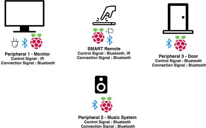
SMART Remote
The SMART remote was the central control unit of the whole system. It acts as a universal remote which has a capability to controls several devices. The peripharals used in our project were needed two types of control signals, bluetooth and IR. The internal bluetooth of the raspberry pi was made use for the bluetooth control, and an additional LED emitter circuit was built to emit IR control signals. The remote also had an embeeded TFT touchscreen which is used for control and displaying the UI. The main components of the SMART Remote are listed below.
- IR emitter circuit
- 2.8 inch piTFT
- Bluetooth
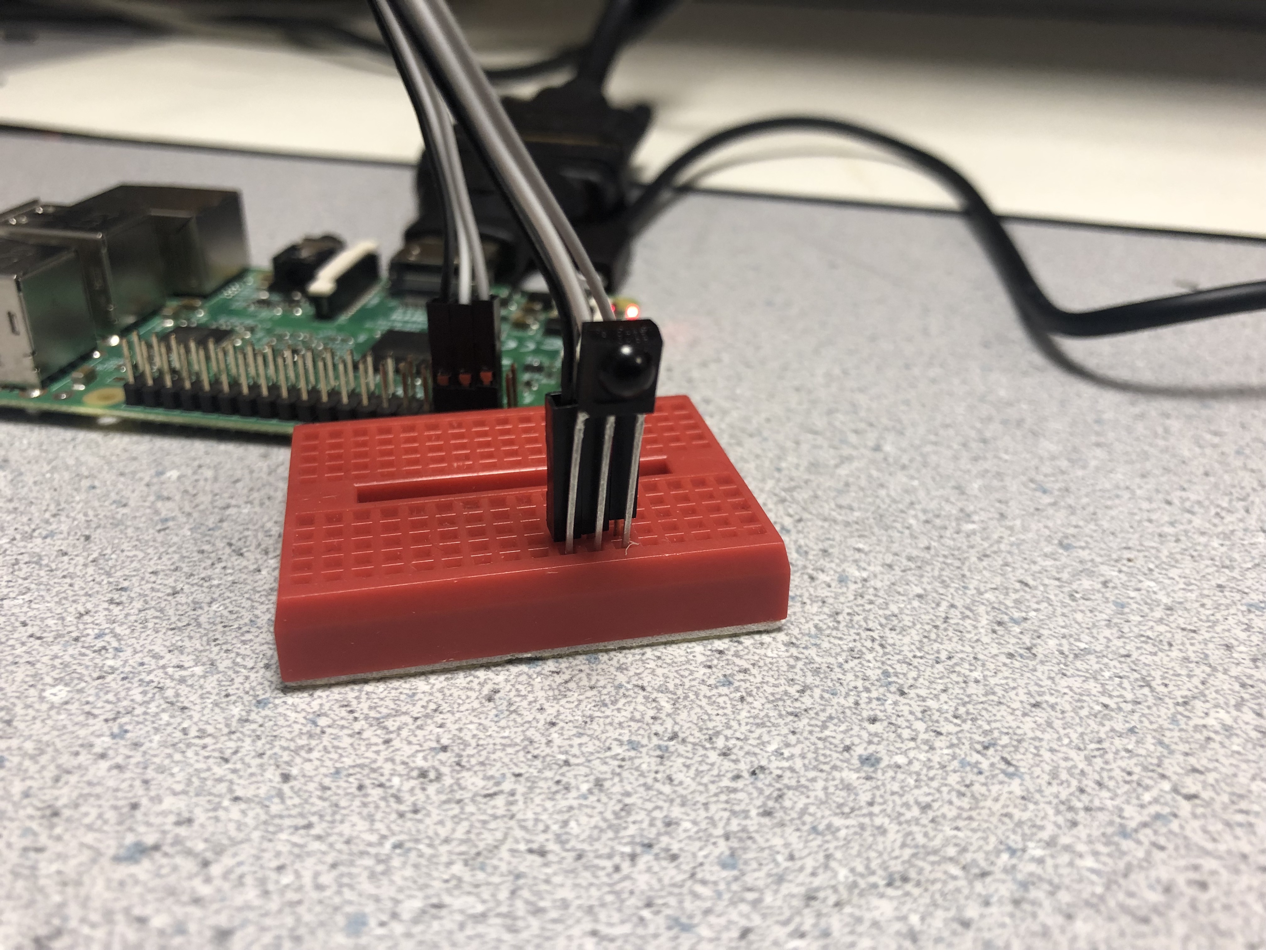
IR circuit
The IR circuit consisted of a transistor to step up the current since the IR led requires a higher current than a GPIO pij can source and also an IR led to emit IR signals. Below is the circuit diagram of the IR circuit.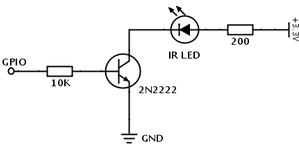
piTFT - User Interface
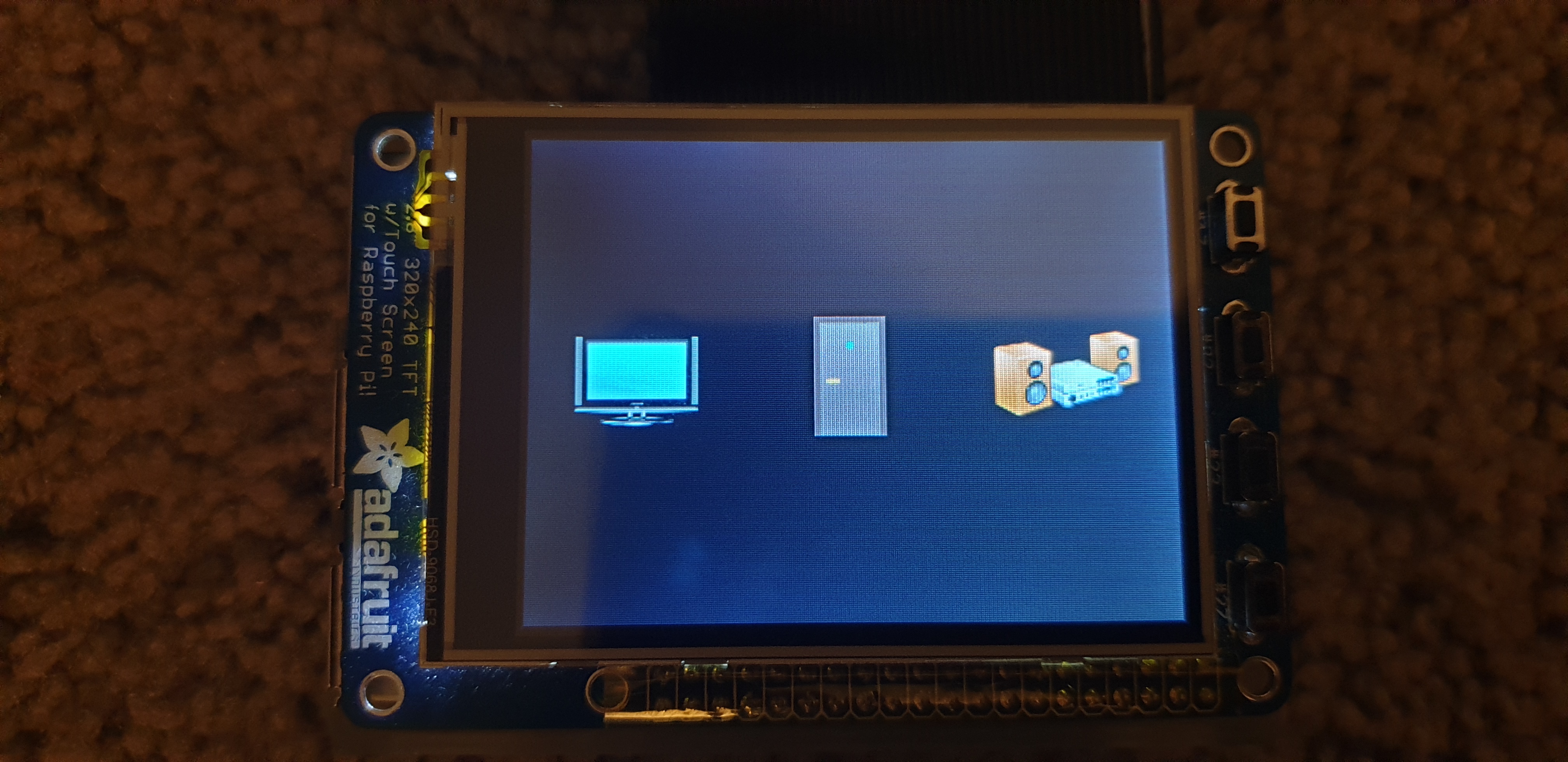
The user interface(UI) was one of the main components of the whole system as UI allows the user to choose options on the remote. The UI was built on the pygame library. The UI consisted of 3 icons, one each for the monitor, door and the music system. Each of these icons had their own submenu. The submenu consisted of peripheral specific control options.
The following is a picture of the UI on a booted up remote.
Control
There was two types of controls available on the remote
- IR
- Bluetooth
Monitor
Play/Pause - Toggles between play and pause : Is achived by toggling a pulse to high for 1 second from the IR led. Back - Returns to the main menu.
Bluetooth control
The Bluetooth libraries used in this project consist of the following python libraries:
- bluez
- libbluetooth-dev
The bluetooth connection is setup using the Bluetooth MAC address of the RPi which is to be considered as server. The bluetooth MAC address can be found out typing "hciconfig" in the terminal. The bluetooth protocol used here is RFCOMM. The server is setup using its own bluetooth MAC address and using the same bluetooth MAC address on the client side. A port unique to a client-server pair is opened and data is send and received using this port. This is explained in detail in the code.
This has to be repeated every time the bluetooth device goes out of range. This is handled appropriately in the code.
Door
Open - To open the door : Sends the string "open" on port 3
Close - Closes the door : Sends the string "close" on port 3
Back - Returns to the main menu
Music System
Play - Play the current song from current position. : Sends the string "1" on port 5
Pause - Pause the current song : Sends the string "p" on port 5
Stop - Stops the current song and puts the next song in queue : Sends "q" on port 5
Next - starts playing the next song. : Sends "n" on port 5
Back - Returns to the main menu
Communication
Bluetooth Communication is achived by a handshake between the remote and the peripharal. As soon as the remote boots up, it tries to establish a connection between the remote and the peripharal. Once the connection is established "ack" mesage is broadcasted from the remote to the peripharal, if the peripharal is in range, it replies with a "ack" message. If not, the remote tries to re-establish connection.
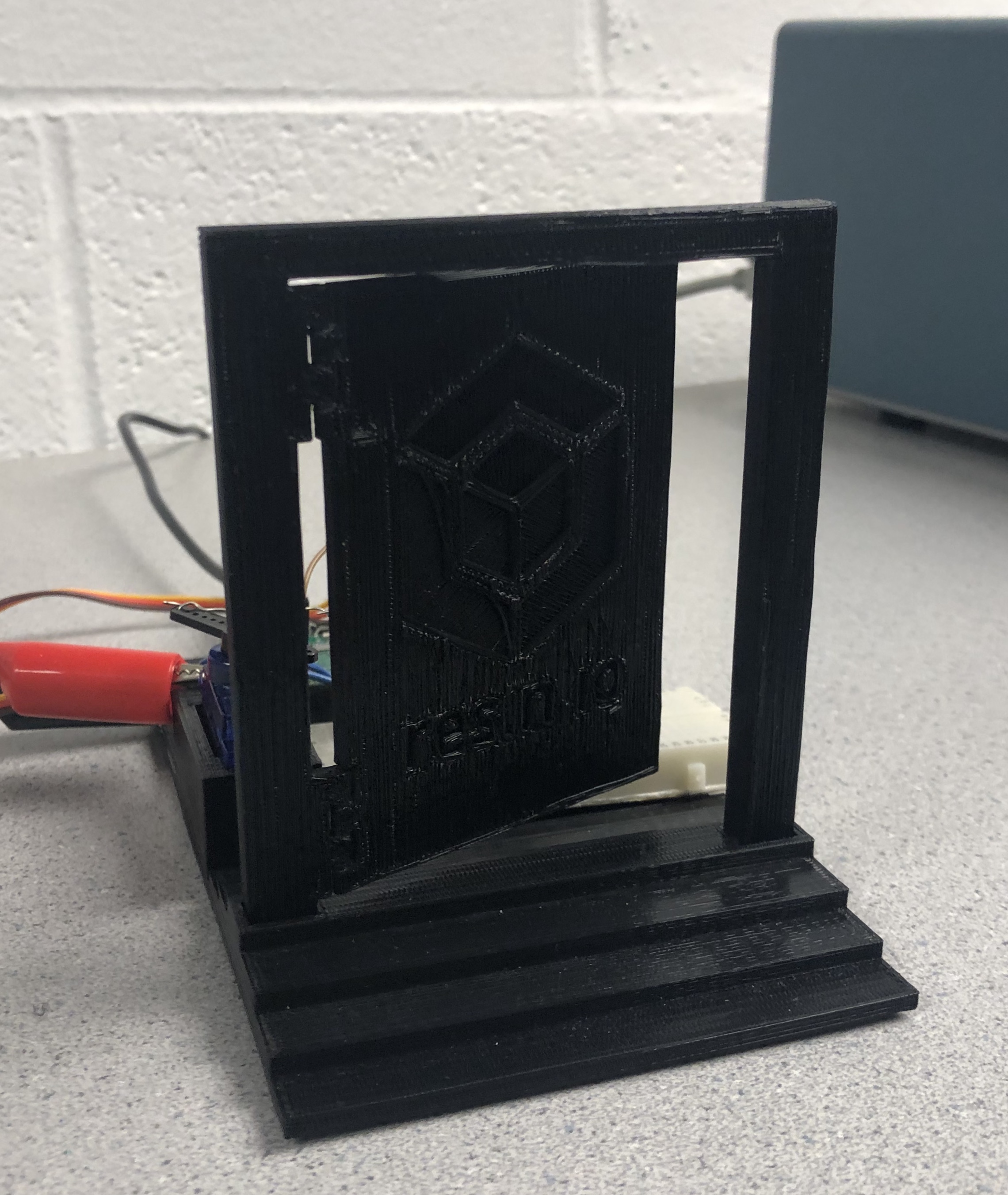
Door
The main components of the door system are
- 3D Printed Door
- Servo
- Raspberry Pi Zero
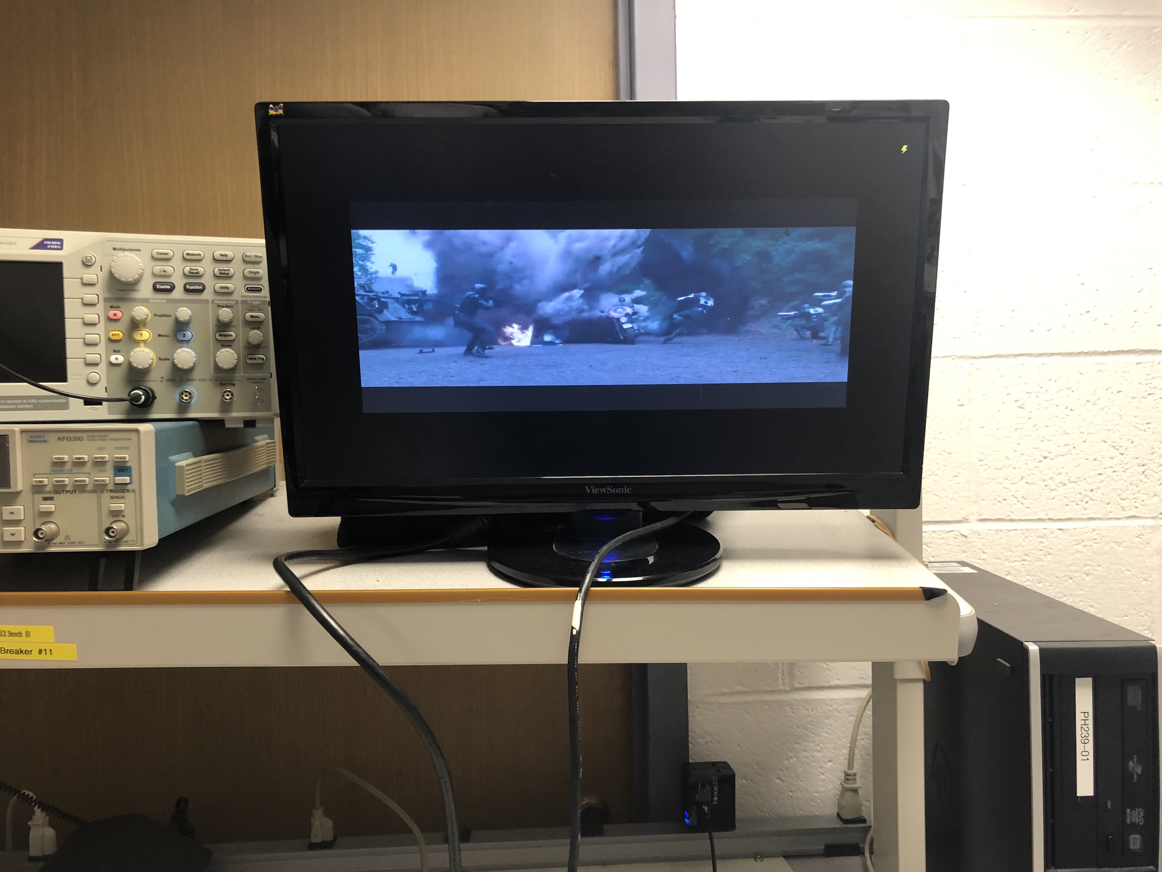
Monitor
The main components of the monitor system are
- Moitor
- IR receiver
- Raspberry Pi Zero
Music System
The main components of the Music system are
- Speaker
- Raspberry Pi 3B
Testing
Since the whole system consisted of several protocols and several peripharals, we needed to test a lot of interfaces for stability.
Bluetooth Communication
The important unit under consideration is the bluetooth system. Establishing the communication is one of the main things in the system. We open a bluetooth port between the device and the remote and send a message. Both the Pis are conected to the monitor. We used a rfcomm_client.py and rfcomm_server.py files in the appendinx to communicate between the two devices. We sent custom messages from one side to another to test communication. After exchanging 1000 strings of random string length between the devices we did not observe any message drop.
Bluetooth Connection
We needed to build an architecure where the device auto pair as soon as they see each other in range. For this we explored two models. One was to check distance between the devices by checking the bluetooth strength and the exchange messages between devices. This method seemed too buggy since the RSSI library used to check the bluetooth strength was very unstable and gives over 30mts in error. So we used a handshake model to establish connection. The handshake was tested for various scenarious as below
- Switching off the bluetooth on the server
- Switching off the bluetooth on the client
- Rebooting the client
- Rebooting the server
- Getting the server out of range of the client
- Getting the client out of range of the server
After testing for all these scenarios we are sure that the system is stable.
TV / Monitor
The initial design was to include a TV and control it. TVs commmunicate using an IR protocol. On a Linux machine
we can control the IR using using the LIRC library. We started looking out for LIRC codes for the Roku TV which ended unsuccessful.
We also tried to get codes for sony RM-YD023 which could control the TV in Philiphs hall. But we could only find codes for RM-YD024 and RM-YD025 and tried them which also ended unsuccesful.
We then switched to a model where we decided to record the differnet signals from the remote and store them and play them back on the IR emitter.
We recorded the power signal from the roku TV and regenrated the signal. We saw that the regenrated signal was exact same as the remote. The below gives a comparison of the singal received from the remote and the signal regenerated.
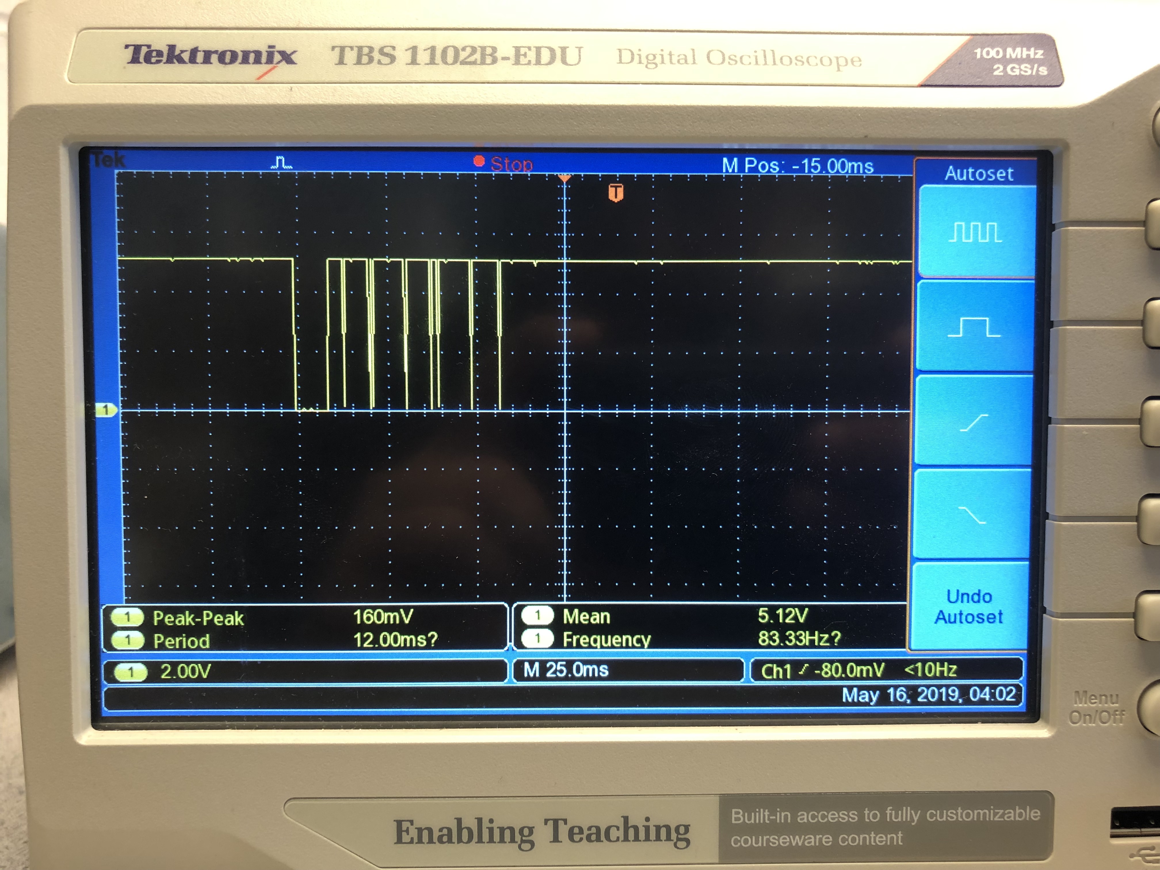
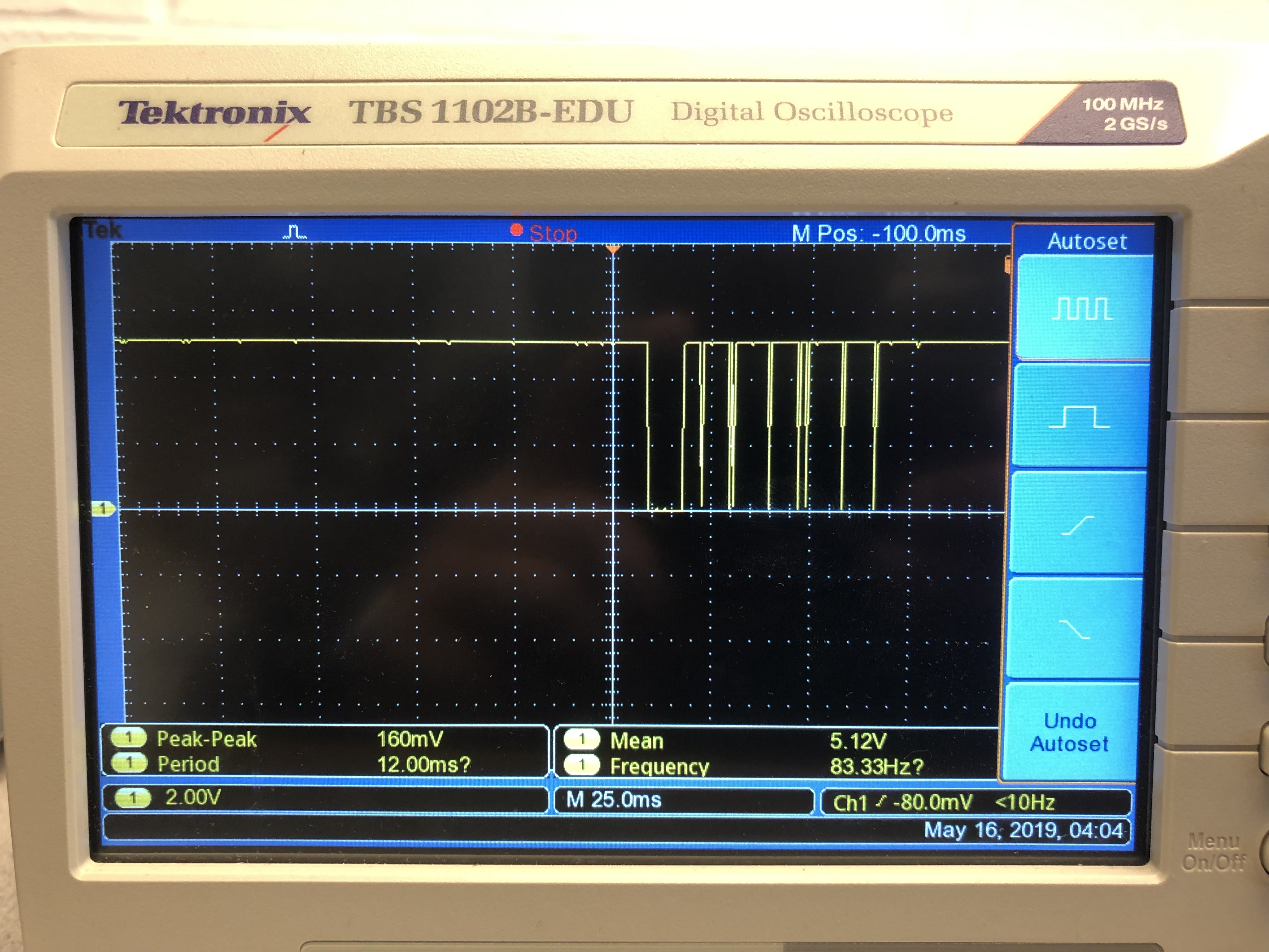 We see that the singal is almost same but the signal still does not control the TV.
We suspect the IR signal does not have the same power or can have a different frequency due to which the TV did not respond.
We see that the singal is almost same but the signal still does not control the TV.
We suspect the IR signal does not have the same power or can have a different frequency due to which the TV did not respond.We then went to a simple system to transport one pulse which is checked on the device end and toggles the option between play and pause. We tried to increase the rate of the pulse and there was a continous reposne from the TV
Music System
The music system continously sends the name of the song to the remote to display on the TFT. The different tests we performed was to cover all the edge cases as below
- 1 hour playback song
- Few seconds Audio clip
- Songs named with special character
- Start the music and go out of range
All these edge cases were covered and the system worked perfectly.
Door
We tested for the opening and closing functios of the door. We toggle the open and close buttons very fast. We ensured that even if the door is executing the previous instructions, the current instructions were stored in the buffer and executed sequentially.
Results
Overall, the project performed very well and all the core objectives were met. The plan was to control 2 peripharals, but by the end of the proect we were able to achive control of 3 devices.
Hardware
The hardware was successfully wired, setup and tested. Most of the circuitry was kept simple to avoid complex issues.
The UI
User interface was successfuly built and was tested for all corner cases. The UI was called on boot and it successfully ran without any issues during the run time. There UI was very stable and did not have any blanking or flickering. The touch screen buttons worked perfectly and showed zero overlap between the buttons.
Dynamic Connection
The system succesfully responded for all sorts of disconeection and successfully reconnected every single time when the devices come back in range. The dynamic refresh was a stable and secure system since it depended on the bluetooth MAC address so it made it really hard to spoof a device, since the bluetooth MAC address is unique
Communication
Bluetooth and IR communication for all devices was very stable and the peripharals continously respodned to contol signals from the remote.
Safety
There were no major safety concerns in this project as we did not use any mechanical parts, sharp objects, or high voltages in our device.
Usability
Several measures were taken to ensure that the system is user friendly. The icons
were displayed on the TFT screen for easy usability. The color schemes for icons to ensure
optimum readability. The internal options were kept simple black and white to ensure equal usability for
colour blind people as well.
All buttons were well labeled and had large enough text fonts and peripharals and the circuits used were quite simmple avoid confusions.
Conclusion
Our Thoughts
The project met all the goals that were set and exceeded by implementing one more peripharal.
The project introduced a novel system as an improvement to the current universal remote models. The project successfully showed context switching can be succefully established using bluetooth and make it an easier universal remote for the user to control.
The project also shows that it does not need an active internet connection like google home or other assistants to contol the devices.
The project also showed that we can use different protocols like bluetooth and IR to acheive control over different kinds of devices.
In short the below picture best describes the project:
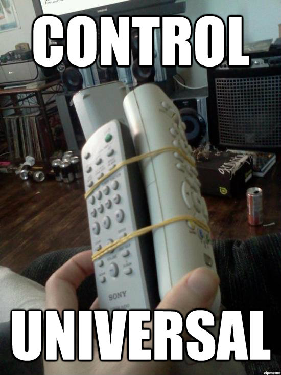


 `
`
Conformance with Standards
There are no applicable standards for this project.
Intellectual Property
The protocols and libraries used in the project was obtained from various sources available online, all of which have been cited in the reference section. There are patent opportunities foreseen but the team does not want to pursue to apply for one.
Ethical and Legal Considerations
IEEE Code of Ethics was strictly adhered to. Safety was given high priority. All signal levels were at 3.3V or 5V and did not pose danger to anybody. All prior work was acknowledged and cited. All data is represented accurately. There are no reasonable legal considerations for this project
Future Work
- One area of improvement could be to develop an android app which will act as a remote and use the internal bluetooth to communicate with the bluetooth beacons.
- We can use BLE(Bluetooth Low Energy) systems which has lesser and a more stable range which will help to establish context in a better fashion. We can also add a feature for the beacons to be able to be controlled by WiFi, this would help some peripharals which the user can connect over larger distance by choice (and not context).
- We can also build and architecture of multiple remotes and multiple devices which allows multiple remotes to control the same device. We could also add a security feature to restrict control to a device for a specfic set of remotes, which could be controlled by the device system administrator.
- We presently have just three common devices. Future work could be involved to add all the IOT devices to control.
- Present control just uses two protocols, bluetooth and IR for communication and control. We can add more prootocols like NFC, RFID, WiFi, etc to cover wide range of devices.
Appendix
Appendix A - Project Inclusion
- The group approves this report for inclusion on the course website.
- The group approves the video for inclusion on the course youtube channel.
Appendix B - Schematics and Circuits
IR Emitter Schematic
IR Receiver Circuit
Appendix C - Raspberry Pi Pinouts
| Device | Component | Pin |
|---|---|---|
| Remote | IR emitter | GPIO 26 |
| Monitor | IR Receiver | GPIO 14 |
| Door | Servo | GPIO 19 |
Appendix D - Cost Details
| Vendor | Description | Quantity | Unit Cost($) | Total Cost($) |
|---|---|---|---|---|
| ECE Department | Raspberry Pi 3B | 1 | 35.00 | 35.00 |
| ECE Department | Raspberry Pi Zero | 2 | 5.00 | 10.00 |
| Tower Pro SG90 | Micro Servo | 1 | 5.95 | 5.95 |
| DigiKey | TSOP 34156 IR Receiver | 1 | 1.33 | 1.33 |
| DigiPart | KN3904 NPN Transistor | 1 | 0.07 | 0.07 |
| Mouser Electronics | TSAL 6400 IR emitter | 1 | 0.49 | 0.49 |
| XLeader | Bluetooth Speaker | 1 | 15.00 | 15.00 |
| Amazon | Aux Cable | 1 | 2.00 | 2.00 |
| ECE Department | Breadboard | 2 | 5.00 | 10.00 |
| Total | 79.84 | |||
Appendix E - Work Distribution
We worked closely together throughout the project. We worked on all the circuit design and testing in the lab and programming together in the house since we had two screens at home. When writing the final report, we split the parts and worked on different sections. Anirudh worked on Conclusion, Future work and Introduction and Gururaj worked on rest of the content and the website design and also the porting content on the webpage.