Playing an instrument is a hobby a variety of people around the world can appreciate. It is not however, easy to learn how. Furthermore, playing an instrument can sometimes be tedious. What if there was a way to enjoy the sounds of live music, by only having to source 12V and 5V? BassBot is an important step into that future.
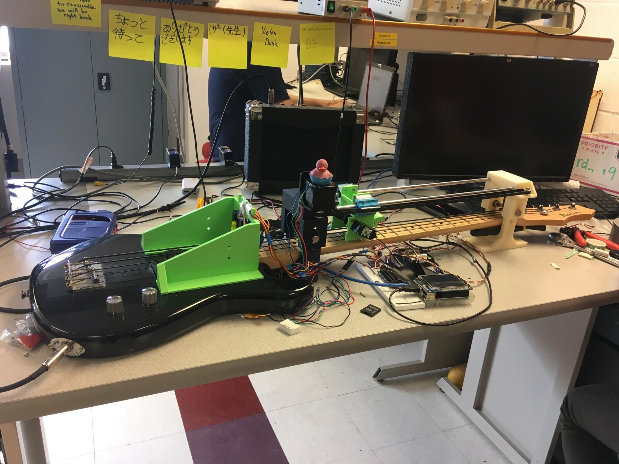
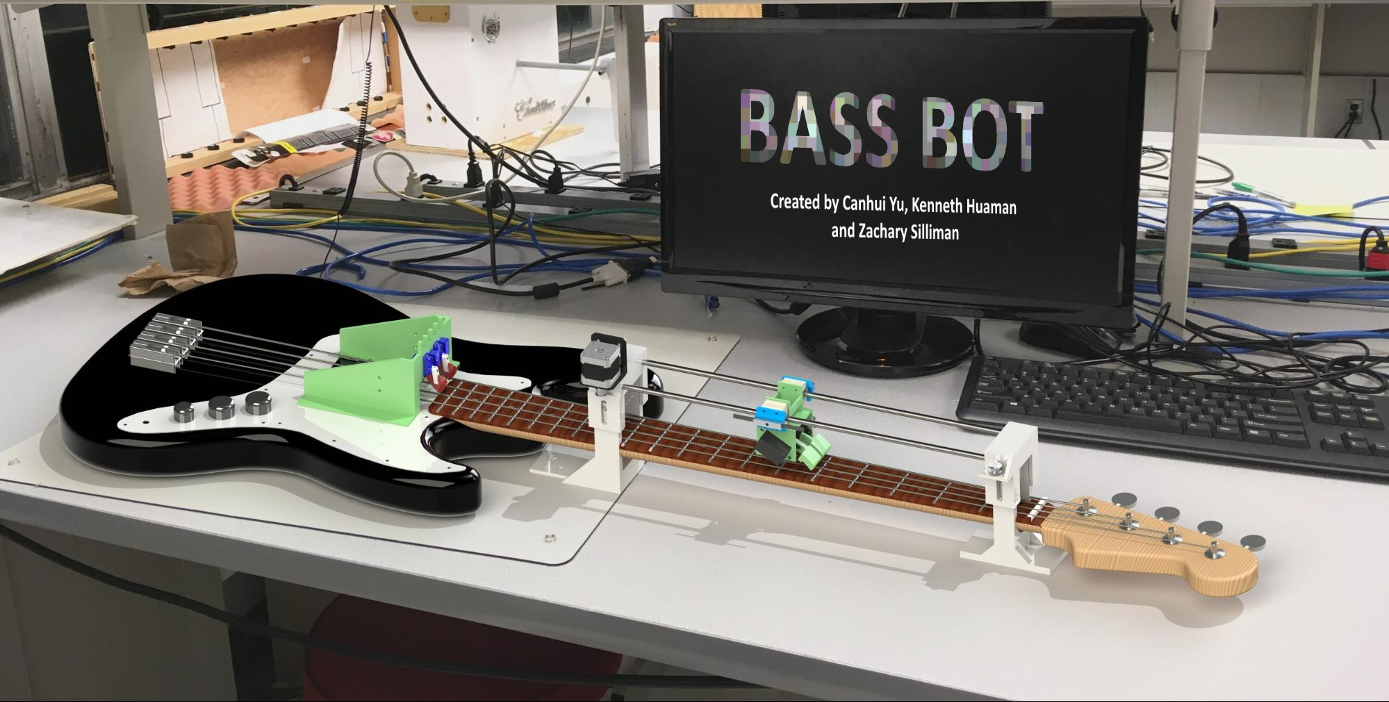
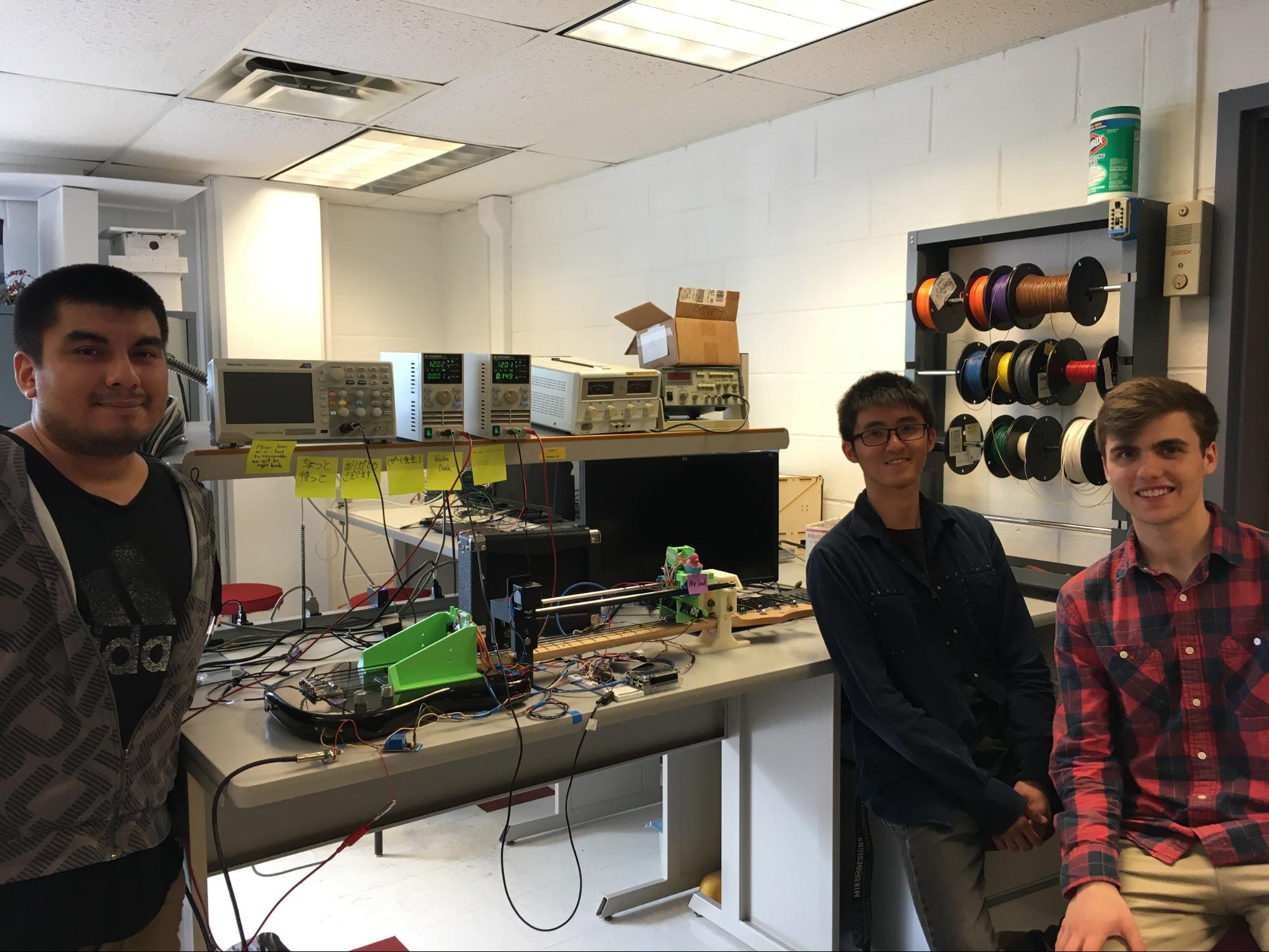
Figure 1.1. Image of completed project.
When beginning this project, there were many ideas that we originally had. In each subsection below, we will start by briefly discussing prior considerations and failed approaches before describing the resultant in detail.
The major mechanical systems for the Bass Bot are the plucking assembly and clamping assembly and they correspond to the motion of plucking the strings and clamping the threads respectively. The plucking assembly consists of four TowerPro SG 92 micro-servo motors which are responsible for plucking each individual string and a housing bracket to hold the motors in place during operation. The clamping assembly has more mechanical components and it consists of a rail subassembly and a servo subassembly. The rail subassembly is essentially a linear rail driven by a NEMA 17 stepper motor to deliver the servo subassembly to clamp the threads at specific location. The servo subassembly serves as a housing for two Parallax Standard Servo and bridges the servos to the rail subassembly. Each assembly will be discussed more in depth in the subsection below and some renderings are included to provide a better visual explanation.
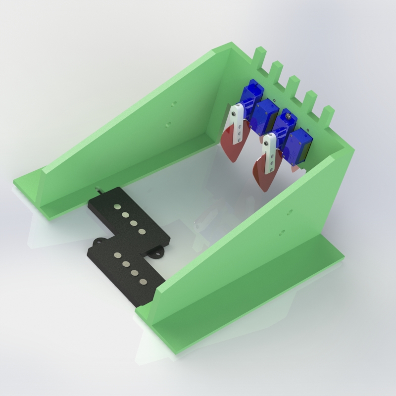
Figure 1.2. Rendering of plucking assembly.
Figure 1.3. Animated breakdown of plucking assembly parts.
The plucking motion of Bass Bot is accomplished by four servo motors. The servo head attachments are 3D printed and they are mounted to the servo by one set screw to the side and one screw come with the servo. The set screw to the side prevents the servos from “slipping” the head attachment as the torque required to pluck the string is actually quite high. The picks are attached to the head attachment by three M2 screws. There are brass inserts in the head attachment because creating threads in 3D printed parts are difficult and not reliable. Finally, the housing bracket is attached by two screws pre-existed in the guitar’s pickup. Because the pickup would pick up all the vibrations above it, we extended the housing bracket to be 150 mm long so that the noise from the servos are not picked up by the amplifier. Lastly, the columns above the housing bracket are for better management of the wires. We went through five iterations of the plucking assembly, and some of the reasons are: 1. Motorhead attachment slipping; 2. Add hole for mounting to the guitar; 3. Extend housing bracket to reduce noise; 4. Wire management.
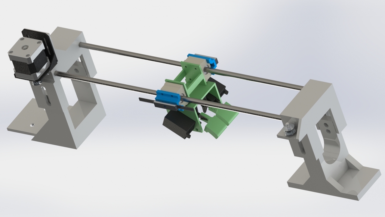
Figure 1.4. Rendering of clamping assembly.
Figure 1.5. Animated breakdown of clamping assembly parts.
The location of where to clamp the threads is determined by the rail subassembly. The rail assembly consists of one stepper motor & bracket, two stands (3D printed), two steel rods, two linear bushings, two pulley gears, and one housing bracket connected to the servo subassembly. Initially, one of the stands is designed to be mounted to the base of the guitar but it turned out the screws are connected to the thread board so they are too risky to unscrew. During operation, the bass guitar rests on the stands and the normal force keeps the entire assembly in place. Two bushings (purchased from Amazon) are used to support and guide the servo subassembly to move linearly.
The servo subassembly provides the necessary forces and impulse to clamp the threads to the thread board. We have spent the most time working on this part and it is considered to be the most challenging component of the project. Initially, the “clamping” motion was designed to be achieved by one linear solenoid mounted with the bracket connected to the housing bracket. However, our experiments proved that the solenoid can only clamp the two center strings in place as all four strings doesn’t lie on the same horizontal plane. We attempted it with two solenoids but the force was still not strong enough (and the two solenoid assembly later evolves into the bed of Mr. Duck). Suggested by the instructor, we decided to use two parallax servo in place of solenoids to accomplish the clamping motion and it is proven to be efficient. The final assembly consists of two servos & servo arms and one housing bracket. Since the strings doesn’t lay on the same horizontal plane, two servo arms are designed and each is responsible for clamping two strings.
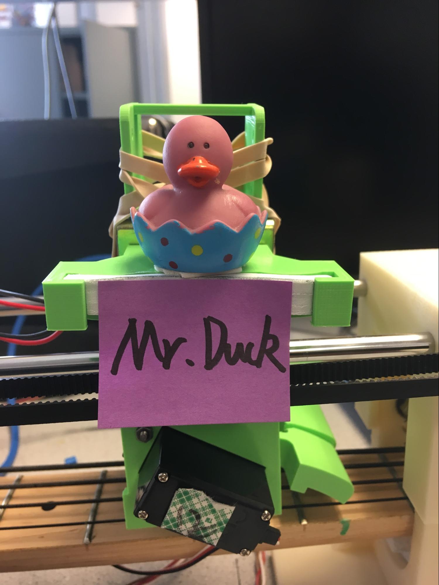
Figure 1.6. Our beloved Mr Duck.
Mr. Duck is the last component added to the Bass Bot the day before the demo. Since we had spent so much resources working on solenoids but they unfortunately end up not being used, we decided to put it on top of the servo subassembly and sit Mr. Duck on top. After a song is completed, we triggered the solenoids to move back and forth frequently to create a Mr.Duck happy dance.
For the plucking mechanisms, we initially considered using small solenoid to push an orthogonally positioned guitar pick back and forth to strum the guitar. We decided against that because turning a solenoid on and off would result in two strums. If we left the solenoid on, then it is foreseeable for it to overheat from the current draw. Furthermore, the solenoid couldn’t be controlled to extend a certain distance, extension is a property of the product. We could not guarantee that the pick would not go to far and interfere with the strumming of an adjacent string. We decided to use 4 cheap servos to pluck by going back and forth between two angles(decided based off of PWM frequency and not actual angle, see code for details). Since torque wasn’t a huge issue given that the guitar pick was very light and that it wouldn’t take too much force to strum a string. We drove them using PWM to rotate between points where we deemed that the pick was far enough from the strings to not interfere with strumming of other strings, but close enough to quickly strum its corresponding string. However every now and then they would displace so we would have to manually tune the servos to rotate to positions which we liked.
From the beginning we knew that we wanted to use a CNC rail to move the clamping mechanism across the fretboard. A stepper therefore was a natural choice. As many of us were unfamiliar with stepper selection, we selected the NEMA 17, which had a lot of documentation and instructional sources. To drive it we originally chose the l298n driver, which could drive two dc motors or 1 bipolar stepper motor(such as the NEMA 17). The driver took in 4 inputs from the PI, each which would activate two inductive coils, referred to as coil A and B by the NEMA 17 spec sheet. Below can be seen
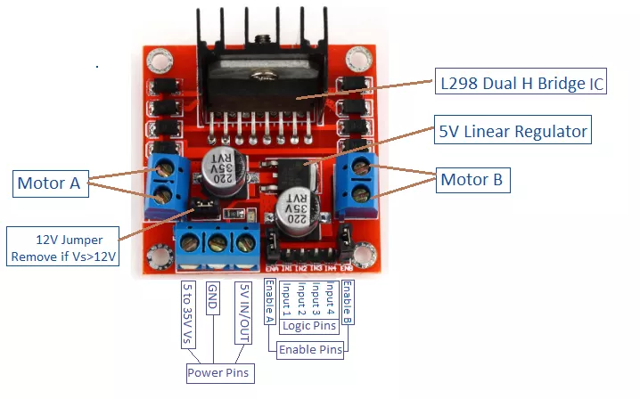
Figure 1.7. Motor controller which we later found did not work properly.
We unfortunately suffered some issues when attempting to run test code, in that the stepper did not always change direction when we wanted it too. After spending a significant time debugging, we decided to instead use the DV8825 which only needed a pin for step and a pin direction from the PI as control.
One of the principal considerations for the driver below is the current limit. We were made aware that current limiting the Voltage supply doesn’t have the same effect since some kind of stepping down is performed. To limit the current to 1 amp as specified by the NEMA 17, we had to set the Vref to 0.5 V. Vref can be measured and changed by the screw on the bottom right of the front view of the board. To change it we wrapped a screwdriver in electrical tape and attached a probe to the metal part of the screwdriver to simultaneously tune and probe. It was a bit difficult, but we moved it where it had to be. Regarding the driver itself, it had fairly simple control. Sending out 1 step at a time in a given direction within a for loop, the min delay(corresponding to the fastest speed) is 0.0004 seconds. Wiring the stepper to the driver requires some care. There are cases where wires corresponding to the ends of the coil are not where they should be. Using a multimeter probe we verified the two pairs matched what was shown on the data sheet. We matched them as A going to A1, A\ going to A2, and likewise for Coil B.
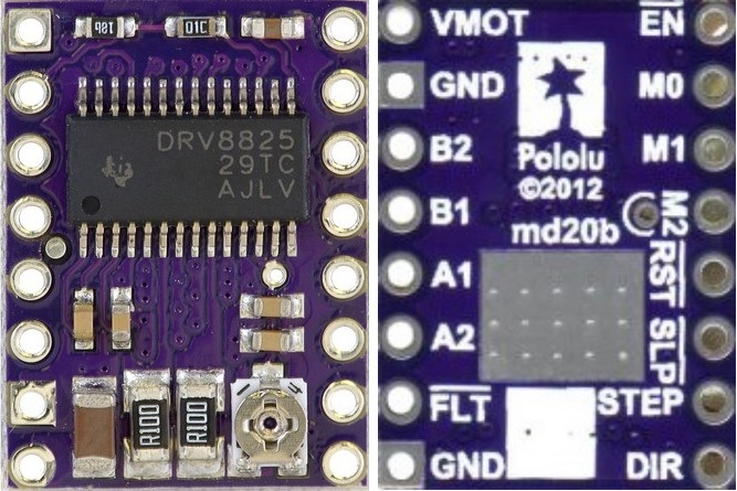
Figure 1.8. DRV8825 stepper motor controller used in our final product.
Our initial design for the clamping involved a solenoid to press down an arm shaped to clamp all the strings. This was not strong enough and the arm would rotate about the cylindrical head of the solenoid. We then decided to use two solenoids to both add more force and to remove the issue of the revolving arm. Unfortunately this still wasn’t strong enough. Under the advice of professor Skovira, we ultimately decided that the servos would be better suited to clamping (an immediate advantage was that he was able to supply us with the servos). We used the hardware pwm capable pins- GPIO12 & GPIO13. We drove them in different ways to reduce excess vibrations on the string when clamping. Initially we had them step about 70% of the angular distance to a “clamp” before going the rest of the way. Once the whole setup was finalized we used our eyes to make the servos raise the arms to a position just above where they would be “clamped” so that they wouldn’t interfere with string vibration when not clamped. We could not get rid of the clamps vibrating the string, so we found a neat usage of our spare relay board. We explain below.
Initially our plans for the relay board was to manage the large voltage required by the solenoids. This was since they can only be sent high voltage or not to activate it, we needed a safe way to electronically switch them. The solenoids we had selected operated at 12V with a max current of 2A(though operation current was around 0.5A). We found several relays rated at 30V 10A, but with a varying number of channels. Once our ideas progressed to only using the solenoid for the clamping, we decided to buy a 2 channel relay(one extra channel in case we needed it). As explained above in the parallax servo section, even two solenoids weren’t doing the job correctly so we scrapped the solenoids, but still had the relay board left over. From further testing with the parallax servos we noticed that when clamping, the strings would vibrate slightly as if strummed. We couldn’t fix this issue by changing clamping speeds or materials, so we had an idea to cut off signal to the amplifier when clamping and only turn it on when strumming. To do this, we opened the aux connection by unscrewing the socket of the bass guitar and found two wires, GND and audio. We tried removing the audio wire and moving it to the left terminal of a relay channel. We shorted a wire from the right terminal of the same channel to the GND of the aux socket. Finally we connected the center terminal to the hole of the aux socket where the audio cable was formerly soldered. This allowed us to switch the output between and audio signal and a flat ground.
We still had the solenoids left over and wanted to get some mileage out of them. We therefore came up with Mr. Duck. Mr. Duck is a happy mallard duck from NY who somehow wound up in our project box. We fastened him (safely) to the solenoids and placed the solenoids on top of the clamping arm. We soldered the two red wires of the solenoid pair together, and then did the same for the grounds. We connected the grounds to common, connected the 12V 2A power supply to one of the switch terminals, left the other open, and connected to last terminal to the soldered red wires. At the end of the music sequence, Mr. Ducky will dance.
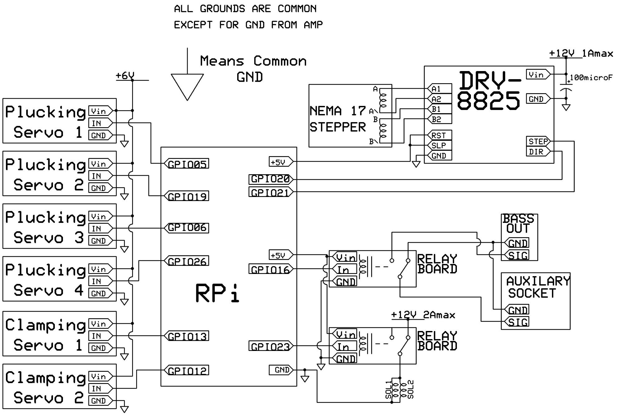
Figure 1.9. Circuit diagram of final product.
Note the two relay boards were included in a single product, the two channel 30VDC 10A relay board. The four plucking servos are different than the Clamping servos. GPIO pins 12 and 13 have hardware PWM. As a second reminder, set the current limit for the stepper driver on the board itself, it is different from the current limit set by the power supply. This project also operates under the assumption that a PiTFT is already connected to the RPi
The design process of the graphical user interface (GUI) went through several iterations. The user interface could be divided into two main sections, the play screen and song select screen. These two interfaces allowed the user to control the bass-playing mechanism. The play screen allowed the user to play a particular note, while the song screen allowed the user to select a song from a short list of pre-programmed songs. Additionally, the interface included a main menu screen and credits screen which can be seen in Figure 1.2. The entire GUI was programmed in python using the library Pygame and was displayed on a small PiTFT touchscreen.

Figure 1.10. Main Menu Screen (left), Song Screen(middle) and Credits Screen (right)
The play screen was the most complex of the screens. The initial thought was to have the user choose letter notes (i.e. A, Bb, B, etc.), and map those notes onto the fretboard to be played. Unfortunately, the mapping from letter notes to frets and strings on a bass is not one-to-one. For every letter notes, there could be multiple possible notes to play. To solve this issue we implemented an octave button to allow the user to select which octave to play the letter note. Ultimately, this made the GUI more complex than it needed to be. We soon scrapped this approach, favoring a cleaner GUI that allowed the user to select fret and string pairs rather than specific notes. The user could also see the entire fretboard by scrolling with the arrow buttons displayed. The evolution between the two interfaces can be seen below in Figure 1.1. Additionally, the song screen simply contained three buttons, that would call a song-playing function.
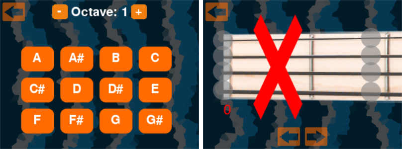
Figure 1.11. The earlier GUI (left) adjacent to the current GUI (right).
There is a large ‘X’ on the right letting the user know that the first fret is not available.
Once completing a skeleton for the GUI, we had to make it interface with the hardware. There were four sections that needed to be implemented, the stepper motor, picking mechanism servos, fretting mechanism servos and Mr Duck’s solenoids. We encountered several problems trying to get the stepper motor working. After trying sample code from three different sources, we still could not get the stepper motor to step properly. It would occasionally switch directions for seemingly no reason. We transitioned to a different stepper motor controller that worked much simpler. Instead of having to send a complex stepper motor sequence, the software only had to send a high signal to the “step” pin on the controller and either a high or low signal to correspond to clockwise or counterclockwise. To accurately determine the location of the belt, we measured the number of steps it took to reach each fret from an origin point at the end of the bass. As the stepper moved, it likely accumulated error, however, we were operating on a relatively large scale so several steps of error in either direction did not cause much error.
In addition to the stepper motor, we controlled four individual stepper motors. To control the servos, we created a python class called Pick, to manage the internal states of each pick. The main function within the class was pluck, in which it moved the pick across the string. Internally, it kept references to the location of the pick so it could be strummed back and forth. This class architecture allowed for the servo locations to be easily tunable if anything suddenly became misaligned. Since we were using software PWM to control these servos we initially ran into trouble with excessive vibration of the servos. To solve this issue we simple set the duty cycle to zero at the endpoints of the plucking motion.
Control of the fretting mechanism was fairly straight forward. We moved two standard servos up and down between a released and clamped position. We started with software PWM, but again noticed excessive vibration. We wanted to ensure that the clamped position applied a constant force in order to avoid unnecessary fret buzz. We chose to use hardware PWM to provide a more stable signal. However, we noticed that when we clamped the strings a loud noise would ring. Our initial solution to this problem was to lower the servos slower. Although this helped a little, it was not as good as we wanted. Our final solution was to turn the signal to the amplifier off prior to pressing the string and turning it back on once pressed. This worked extremely well.
Last but not least, we added Mr Duck’s celebration. After successfully playing a full song, the solenoids controlling Mr Duck would bounce in and out quickly, simulating a victory dance. We felt guilty not using our solenoids and decided to put them to good use.
The first three weeks of the projects were focused on hardware testing (i.e, design iterations of plucking assembly and clamping assembly, and testing on servos and stepper motors) and the last week were focused on system level hardware testing and software testing. We performed four design & 3D printing iteration on the servo housing bracket and 5 iterations on the solenoid attachment (but we ended up not using the solenoid assembly to clamp the threads due to lack of force). We tried two different stepper drivers on our stepper motor and decided to use the later one that we considered. In our system control, we used a combination of software PWM and hardware PWM to control our servo motors and a two channel relay to control the receiving end of the amplifier as well as Mr.Duck. Despite all the challenges that we encountered, we managed to finish all the testing and achieved our initial objectives by the demo date. The Bass Bot was able to play certain notes and two songs (Pachelbel - Canon and Happy Birthday Song) upon user’s control on the GUI. The testings videos for the songs are shown here:
Figure 2.1. Pachelbel performance.
Figure 2.2. Happy Birthday performance.
Regardless of certain latency due to the hardware, our Bass Bot meets our objectives and is able to play certain notes and simple songs upson user control. In addition, the system is able to perform repeated actions without failing so we consider our project to be a great success. Although our project was completed before the deadline, future work is needed to make the system more robust in the perspectives of hardware and software.
Our initial objective is to make an automated system to play the bass guitar upon user’s control. During the testing process, we discovered that there are many things that we need to consider for improvement in the future. And we divide them into three categories:
Many components of the system are made of 3D printed parts for rapid prototyping, but these plastic materials are not good choices for a robust system in the long run. Additional geometric tolerances analysis need to be performed in the next generation of prototype. The servo subassembly can be redesigned to apply forces more efficiently to clamp the threads. After the system design is finalized, future work in the mechanical perspective includes making the system more robust and making it workable to other bass guitar models.
Selecting a better stepper for one. Seeing as how a large constraint for this project is the budget, this should be considered carefully.
Our future plans for software are to improve the UI. Currently, all code runs in a single thread, meaning that while a song is playing, the GUI is frozen. In the future I would like to incorporate multithreading to prevent the UI from freezing while the mechanism is moving.
We really appreciate the people and organizations who have helped us along the way while building Bass Bot. Without their help Bass Bot would not have been possible:

|
Canhuicy428@cornell.edu Canhui is a senior majoring in Mechanical Engineering and an outdoor enthusiasts who is mad excited about exploring the outdoors. Outside of class work, Canhui enjoys rock climbing and trying many different things in the outdoors. |
 |
Kenkch96@cornell.edu Ken is an MEng student in Electrical and Computer Engineering. He attended his undergrad at Cornell as well and enjoys reading topics from linguistics or history in his spare time. He used to be an avid swimmer. |
 |
Zachzjs9@cornell.edu Zach is a senior in Computer Science who enjoys playing bass guitar. He is currently in a band at Cornell called The Laurens. Additionally, he is also a competitive eSports player, having represented Cornell in an intercollegiate tournament. |
| Part Name | Source | Price |
| Linear Motion Rod | link | $18.99 |
| 2 Channel Relay | link | $6.79 |
| M2 Bass Insert | link | $0.68 |
| Bushings | link | $5.50 |
| M2 Screws | link | $0.79 |
| Belt and Pulley | link | $8.00 |
| Stepper Motor | link | $12.99 |
| Stepper Motor Bracket | link | $3.66 |
| DRV 8825 Stepper motor driver | link | $2.198 |
| Tower Pro Servo | borrowed from instructor | $0 |
| Parallax Standard Servo | borrowed from instructor | $0 |
| Total: $59.60 |
Due to the large volume of code, we did not include all of it in this webpage. Instead we have a link to a public GitHub repository.
Github RepositoryThanks for reading!