Automated Foosball Player
ECE 5725 May 15,2019
Caroline Chu (cc2295), Joyce Huang (sh2393)
Demonstration Video
Introduction
The automated foosball goalie allows one to play foosball without another human player. The goalie is attached to a servo and moves on a linear bearing according to the direction of the incoming ball. A camera is attached to the goalie and uses computer vision to determine the location of the ball. More specifically, color detection is implemented, allowing the goalie to move left or right depending on the location of the ball. The goalie stops the ball by positioning itself directly in front of the approaching ball.
Project Objective:
- Build a linear bearing frame which can be used in conjungtion with a motor
- Implement OpenCV and use color detection to determing the location of the ball
- Write an algorithm that integrates the motor and the computer vision aspect
Design
Physical Frame
There are three main components of implementation: physical frame set up, servo control, and the object detection camera set up. We first set up the servo and the camera separately, integrate them together, and then set up the physical frame to mount the entire embedded system on it.
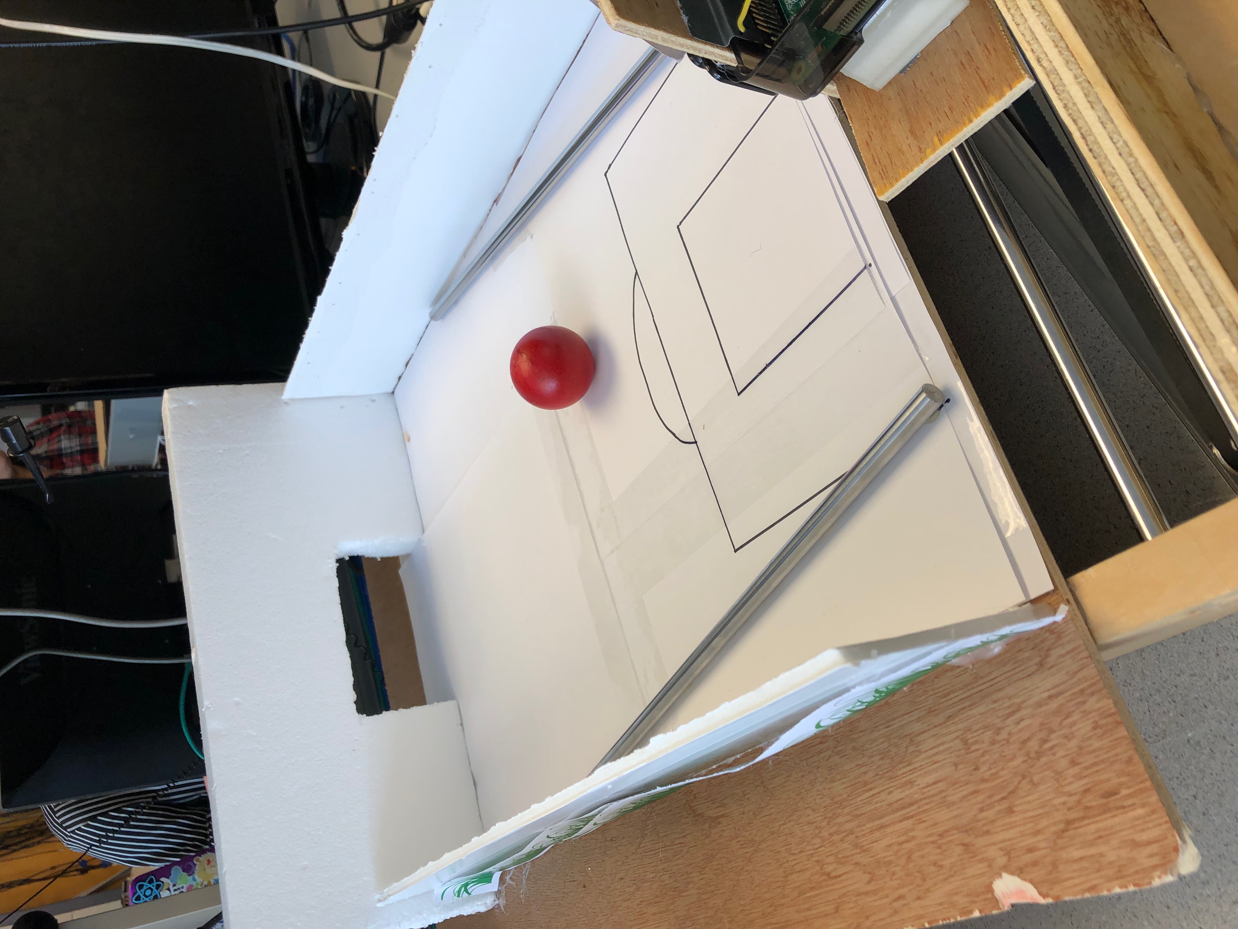
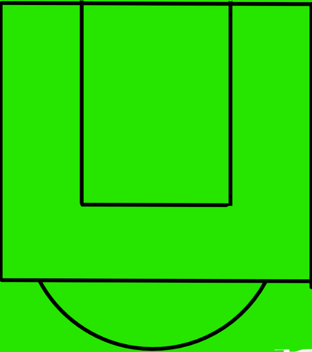
Figure 1. Frame
The setup of the physical frame is illustrated as in Figure 1. The rectangular frame is about 0.4m x 0.5m. One servo is attached on right corner on the inner side along the horizontal frame. This servo is then attached to a conveyor belt. Parallel the conveyor belt, two metal railings are attached through the holes of the vertical frame. The goalie along with the raspberry pi system is mounted onto the railing, allowing it to freely move around horizontally. Finally, we attached the goalie to the conveyor belt, so once the servo is triggered, the servo will pull the conveyor belt so the goalie can be controlled. The playing field is a large flat wooden piece attached on top of the rectangular frame, leveled with the camera’s vision. We picked this design because it gives us more freedom to define the size of the playing field. Two pieces of styrofoam are put along the side as the walls to prevent ball from rolling out of bounds. In addition, two pieces of metal railing are laid on the field to guide the ball toward a specific range. This is necessary because of two reasons. One, the goalie is not able to reach all the way to the end due to the physical set up. Two, if the ball rolls to a position within 45 degrees of the camera (Figure 2), it will be out of the camera’s vision.
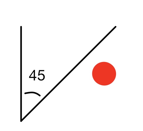
Figure 2. Ball out of Range
Lastly, another piece of styrofoam is set up on the opposite side from the goalie, and we cut out a small rectangular area to allow the ball to roll in. Outside of aesthetic reasons, it is also necessary because the object detection is implemented using color detection and it only detects one red object. It would fail if there are other red objects in the background. Thus we set up this side of the wall to clear out the background. Setting up the physical frame is by far the most challenging part of the project. We acquired the rectangular frame and the railings left over from a laser printer project from previous years. In order to reuse it for our project, we needed to switch out the servo and mount the goalie up. How we attach components together mostly involves a lot of hot glues and duct tapes. However, these techniques sometimes do not work well with plastic or wood or metal. Given that the two components we are attaching together are usually of different materials, there is not a good solution to resolve this, and we would just need to apply extra glue or tape to hold the system together. For example, since both the goalie and the raspberry pi system are attached to the conveyor belt, it is sometimes too heavy to stay attached to the conveyor belt. Thus, we have to hot glue them multiple times. The most difficult part is to attach the conveyor belt to the servo. We collected different components for this so the attaching parts do not fit together, and that left us with hot glueing. This is particularly difficult because the components are small, and the glue needed to applied carefully or else the rolling part would stick together. After many attempts, we were able to hold them together. The final product is shown in figure.
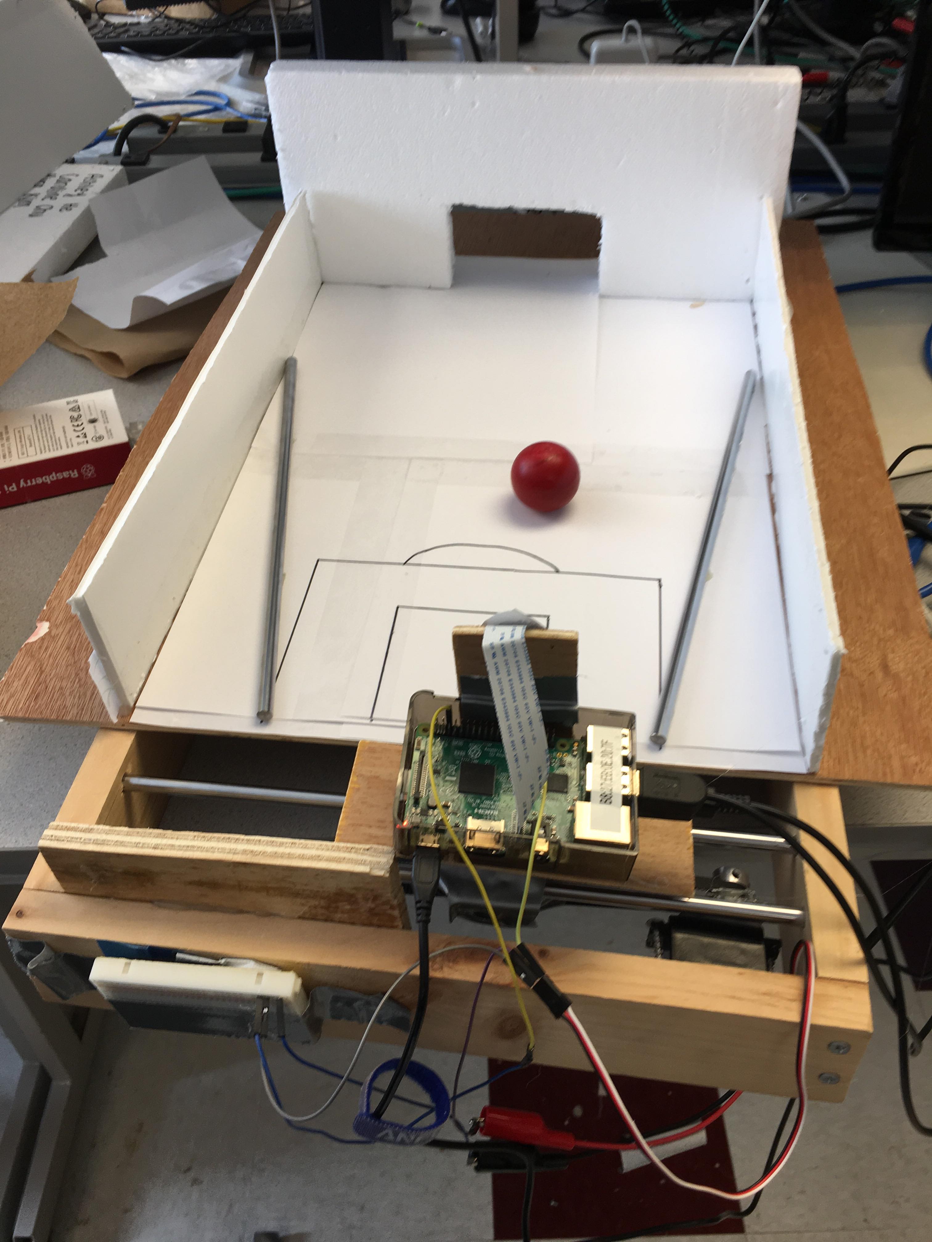
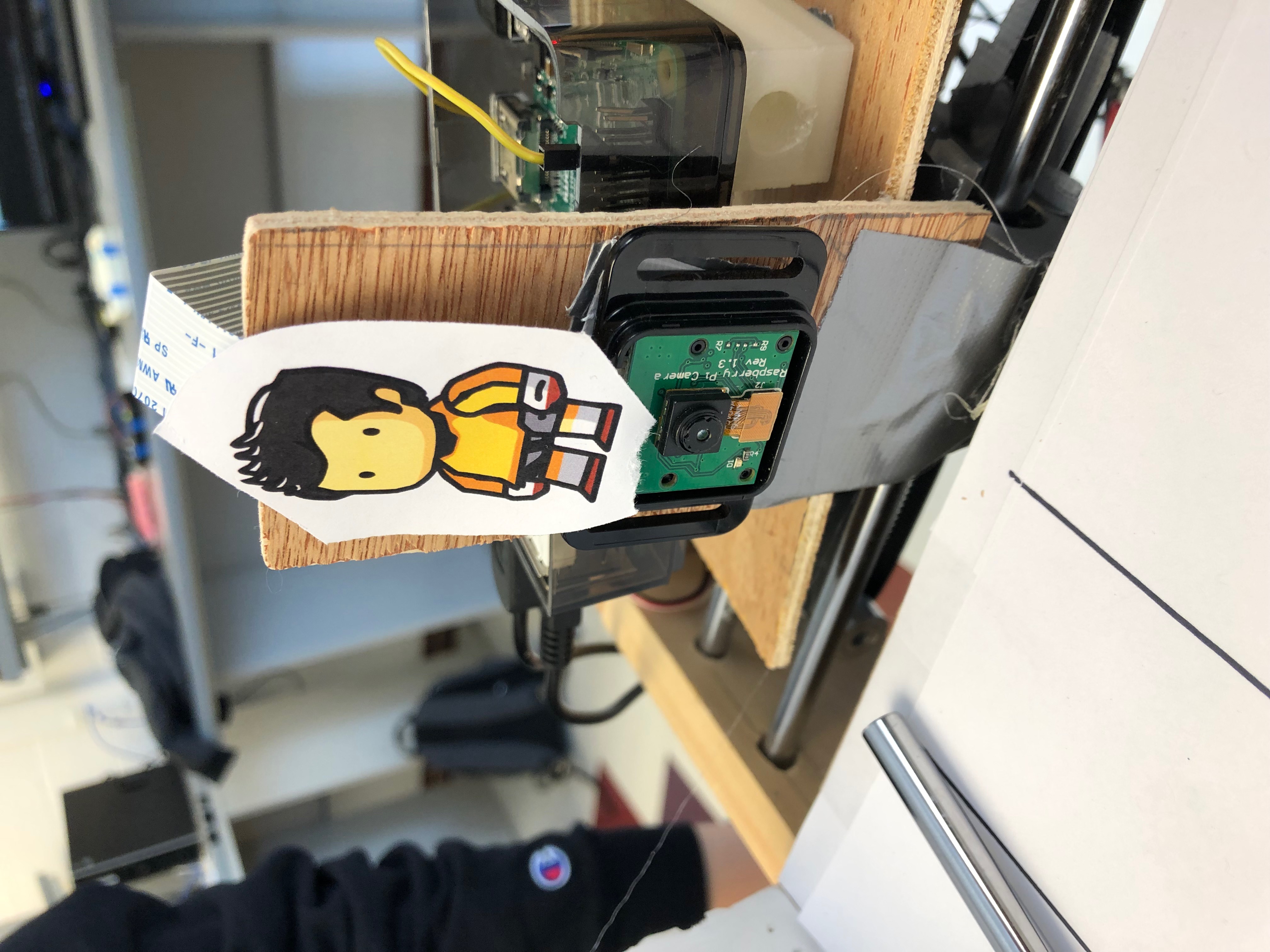
Figure 3. Final Product
Servo Control
Initially, we implemented the conveyor belt pulling mechanism with the stepper motor, as it was already set up on the frame from a laser printer project from previous years. However, the step motor was a poor design choice to our project.The stepper motor is intended for high precision control, so it moves really slow, and it needs four input pins to drive the motor. These four input pins are controlled using a for loop by defining their respective step sequences. For a smooth rotation, the four pins need to be set in a half step sequence.
halfstep_seq = [ [1,0,0,0], [1,1,0,0], [0,1,0,0], [0,1,1,0], [0,0,1,0], [0,0,1,1], [0,0,0,1], [1,0,0,1] ]
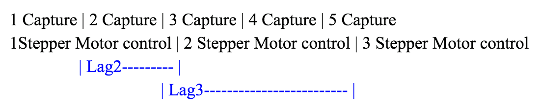
In order to reach full speed, the stepper motor needs time to accelerate. Therefore, in order to have observable movements, the outermost for loop needs to have an iteration number for at least 1000, as shown in the pseudocode below: for i in range(iteration_num): for halfstep in range(8): for pin in range(4): GPIO.output(control_pins[pin], halfstep_seq[halfstep][pin]) time.sleep(0.001) GPIO.cleanup() However, the stepper motor is not continuous, which means in order for the motor to rotate, the main program needs to say in that subroutine. This slows down the entire program: the camera is not able to capture the next frame as the control program is subroutine is still processing the instructions from the previous frames. The control sequence looks like the following

Even the multicore implementation would not be able to resolve this issue. Even though a proposed solution might be that we can continue capturing frame in the foreground and process the motor control in the background, there will still be a big lag. The camera will be able to capture the frame at high speed, but the motor control still requires a long time. Therefore, there will be a big lag between camera capture and servo control . The control sequence will look like the following:
Overall, the stepper motor is not sufficient to meet the speed requirement, but provided unnecessary precision control. It was a poor design choice so we decided to switch to a continuous servo instead. The continuous servo is a perfect choice for the project. It is continuous, does not require as much power, and is able to accelerate to maximum speed instantly. This allows the goalie to look very responsive and allows the CPU to handle image processing task. The servo control code is inherited from the previous labs. From previous labs, we defined a servo class to set up the initialization and adjust controls, and another wheel class which extended the servo class to simply control is forward or backward. We simply needed to instantiate a wheel class in order to control the motor. This shows a good modular programming coding practice.
Object Detection
In order to send accurate command to the servo, the camera is responsible for determining the ball position and move control the servo accordingly. In order to detect the ball, we used PiCamera to capture the image, and then used opencv color detection to identify the ball location. To implement this feature, we attempted several different methods in terms of both sampling and detection mechanism. In the very beginning, we attempted to use the picamera built-in function to capture the image, saves it locally and then opens the file for image processing. Later we found that the opencv library has a built-in function to work with the picamera and convert it to an RGB array, which can be used in opencv directly. Thus, we adopted method. We also tried to do video streaming and object tracking. However, the video streaming is a heavy load to CPU and slows down the processor. In addition, object tracking involves a larger control statement and more image processing technique, which is unnecessary for this project. Thus we abandoned that method and settled with color detection. The downside about color detection is that the camera is very sensitive to the colors. For example, the lighting in the room, sunlight during different hours of the day, or just the shades of the color will cause the color detection to be glitchy. We have found out that the camera detects the color best when the color is highlighted or glossy. However, there is no good materials to paint the ball that color. Instead, we spray painted the ball red.
Combining all of the decisions above, we implemented the control as following:
- The Camera captures a frame as PiRGBArray and turns it into an numpy raw array.
- The BGR color scheme is converted to the HSV format.
- The algorithm selects a predefined HSV color range for the desired red color and construct a mask for this color. It then performs a series of dilations and erosions to remove any small blobs left in the mask.
- It finds the contour of the mask and locates the center position, returns the position relative to the camera as an x,y pair.
- If the detected object is outside of a predefined range limit, then the pi sends a command to the servo to control it left or right.
The full code can be seen in appendix.
There are several assumptions we made in order for this to work. First, there can only be one single red object in range. Second, the ball must be within camera’s vision range. If there is no object in range, then the motor will continue the previous motion until it reaches a predefined boundary. We observed these details by streaming the camera captures on screen, and mark the contour of the mask and mark a red dot in the center of the detected object. The detection will fail if a human hand is in camera’s range, as the HSV color scheme is too similar. In this case, the camera will locate the hand instead of the ball. Unfortunately, even though we have already minimized the control logic to as lightweight as possible, the raspberry pi is still unable to process the image frame and control the servo accordingly real time. There is an observable slack for about 0.2 seconds, which would fail in this mission critical real time system. If the ball rolls slowly enough, though, the foosball goalie can successfully catch the ball, and we have it succeeded while performing test runs.
Results
Overall, our foosball goalie perform as our implementation expected it to be. We knew the assumptions beforehand and limitations, and the system is subjected to those limitations. However, in terms of the originally intended functionality, the foosball goalie system would have caught zero shot against any reasonable opponent due to it slow movement control. Other than that, both the servo and the object detection works as expected.
Conclusion
Overall, we were able to implement a slo-mo automated foosball goalie: the foosball goalie identify the location of the object and goes toward that direction trying to catch the ball. From the result, we learned that performing image processing and the servo control on the same core is insufficient to implement a real time system. We needed a more rigorous control system in order to handle these critical functions. From this project, we learned about opencv image processing, servo control, design methodologies and modular programming.
Future Work
If we had more time, one of the aspects of our current design we would improve is the algorithm of which the goalie moves. Currently, the algorithm is fairly simple and there is a direct correlation between the current location of the ball and the current location of the goalie. We would like the goalie to be able to scan the area and adjust its position if the ball is not within its range. We would also like it to be able to predict the projection of the ball and move to the predicted location. This would require more CPU computation; therefore we would probably switch to using multiple cores at a time. Most importantly, in order to implement a fast enough goalie, we would like to try running this program on multicore, one for continuous servo control and the other for image processing.
Contributions
Caroline Chu (cc2295)
- Assembler the frame
- Work on the original stepper motor idea
- Figure out code for the motor
- Lab report
Joyce Huang (sh2393)
- Work on OpenCV tutorials
- Write code for object detection
- Integrate computer vision with the motor
- Lab report
Materials
- Raspberry Pi $35.00 Continuous Rotation Servo $11.95
- Ping Pong Ball - $0.25 2 Linear Bearing $13.90
- Linear Shafts -Provided in lab
- Breadboard, Wood, Hot Glue, and Wires - Provided in lab
Total: $61.10
Code Appendix
# import the necessary packages
from collections import deque
import numpy as np
import argparse
import imutils
import cv2
#motor controls
import RPi.GPIO as GPIO
import time
from wheel import Wheel

target_left = 300
target_right = 400

max_right = 50
max_left = -20
pos_goalie = 20

GPIO.setmode(GPIO.BOARD)

ControlPin = [7,11,13,15]

for pin in ControlPin:
    GPIO.setup(pin,GPIO.OUT)
    GPIO.output(pin,0)


wheel = Wheel('left', 33)

def move_right(pos_goalie):
  wheel.forward()
  pos_goalie = pos_goalie + 1
  return pos_goalie

def move_left(pos_goalie):
  wheel.backward()
  pos_goalie = pos_goalie - 1
  return pos_goalie

def move_stop():
  wheel.stop()


# construct the argument parse and parse the arguments
ap = argparse.ArgumentParser()
ap.add_argument("-v", "--video",
  help="path to the (optional) video file")
ap.add_argument("-b", "--buffer", type=int, default=64,
  help="max buffer size")
args = vars(ap.parse_args())

# define the lower and upper boundaries of the "yellow object"
# (or "ball") in the HSV color space, then initialize the
# list of tracked points
colorLower = (168, 100, 100)#(-10, 100, 100)
colorUpper = (188, 255, 255) #10

# if a video path was not supplied, grab the reference
# to the webcam
if not args.get("video", False):
  camera = cv2.VideoCapture(0)

# otherwise, grab a reference to the video file
else:
  camera = cv2.VideoCapture(args["video"])

# keep looping
while True:

  # grab the current frame
  (grabbed, frame) = camera.read()

  # if we are viewing a video and we did not grab a frame,
  # then we have reached the end of the video
  if args.get("video") and not grabbed:
    break

  # resize the frame, inverted ("vertical flip" w/ 180degrees),
  # blur it, and convert it to the HSV color space
  frame = imutils.resize(frame, width=600)
  frame = imutils.rotate(frame, angle=180)
  # blurred = cv2.GaussianBlur(frame, (11, 11), 0)
  hsv = cv2.cvtColor(frame, cv2.COLOR_BGR2HSV)

  # construct a mask for the color "green", then perform
  # a series of dilations and erosions to remove any small
  # blobs left in the mask
  mask = cv2.inRange(hsv, colorLower, colorUpper)
  mask = cv2.erode(mask, None, iterations=2)
  mask = cv2.dilate(mask, None, iterations=2)

  # find contours in the mask and initialize the current
  # (x, y) center of the ball
  cnts = cv2.findContours(mask.copy(), cv2.RETR_EXTERNAL,
    cv2.CHAIN_APPROX_SIMPLE)[-2]
  center = None

  # only proceed if at least one contour was found
  if len(cnts) > 0:
    # find the largest contour in the mask, then use
    # it to compute the minimum enclosing circle and
    # centroid
    c = max(cnts, key=cv2.contourArea)
    ((x, y), radius) = cv2.minEnclosingCircle(c)
    M = cv2.moments(c)
    center = (int(M["m10"] / M["m00"]), int(M["m01"] / M["m00"]))

    # only proceed if the radius meets a minimum size
    if radius >6:
      # draw the circle and centroid on the frame,
      # then update the list of tracked points
      cv2.circle(frame, (int(x), int(y)), int(radius),
        (0, 255, 255), 2)
      cv2.circle(frame, center, 5, (0, 0, 255), -1)

  # update the points queue
  dist = 0
  if center != None:
    print(pos_goalie)
    x, y = center
    print("x %d" % x)
    if x > target_right and pos_goalie < max_right:
      pos_goalie = move_right(pos_goalie)
    elif x < target_left and pos_goalie > max_left:
      pos_goalie = move_left(pos_goalie)
    else:
      move_stop()


  # show the frame to our screen
  cv2.imshow("Frame", frame)
  key = cv2.waitKey(1) & 0xFF

  # if the 'q' key is pressed, stop the loop
  if key == ord("q"):
    break

# cleanup the camera and close any open windows
camera.release()
GPIO.cleanup()
cv2.destroyAllWindows()