Multiplayer Game Pi
ECE 5725 SP19
May 17, 2019
Alexander Hatzis (ajh322) & Glenna Zhang (glz6)
Demonstration Video
Introduction
The Multiplayer Game Pi is a single-player or two-player gaming console built on a Raspberry Pi using RetroPie, which is software that combines Raspbian, EmulationStation, and more to run game emulators on the Pi. Featuring two hand-made wireless bluetooth controllers and convenient portability, the console has its own small screen for on-the-go use but can also connect to a larger external monitor via HDMI.
Project Objective:
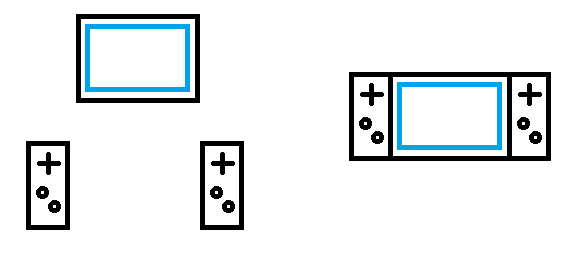
Our objective for this project was to create a gaming system with the option to be portable or connected to a larger screen, and which could easily switch between one or two players. To make the system more versatile, we required that the controllers be either completely separate or optionally separable from the main unit.
Design & Testing
Controller Design
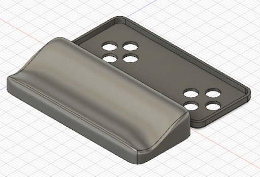
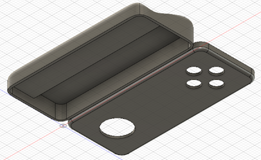
The design of our inputs was critical to meeting the requirements we set for ourselves. Specifically, we wanted our controllers to be either completely separate from the Pi, or optionally separable. The controllers for the Nintendo Switch, where we took much of our inspiration from, can either attach to the sides of the main unit so that it functions as a handheld console, or they can detach from the main unit to be used as wireless controllers. In the case of the Switch, the controllers use physical connections when slotted into the main unit and use bluetooth when detached, but we decided that it would be simpler to just have the controllers use bluetooth all the time. This gave us more freedom in deciding whether to make the controllers attachable.
The first step we took was to use an existing bluetooth controller - one from the Nintendo Switch - and see if we could connect it to the Pi to use as an input device for the games. This turned out to be a relatively simple task; by going into the bluetooth settings provided by RetroPie, we were able to connect to the controller when it was set to be discoverable. Once connected, we simply needed to configure the emulators to correctly interpret the buttons on the controller into inputs that the games expect. Even though this was not a particularly involved process, it was an important step towards understanding how we would need to create our own controller, and bluetooth seemed like the obvious choice since it was supported natively by the Pi’s hardware.
Our next step was ordering several components to create the bluetooth controller. We used the ATMEGA328-PU to make prototyping and programming as simple as possible. The DIP variant that we ordered meant that we could use a breadboard to verify our design before committing it to something more permanent, and the ATMEGA328 can be programmed easily using the Arduino IDE and Arduino libraries. In addition to our microprocessor, we ordered a few small components necessary for the microprocessor to run (16MHz crystal, capacitors, etc.), and tactile push-buttons and analog sticks for controller inputs. We also ordered very cheap bluetooth modules, the HC-06, which was a slave-only serial transceiver. At this point, we did not have a very good understanding of what exactly we required from the bluetooth module, and this would cause some issues later on.
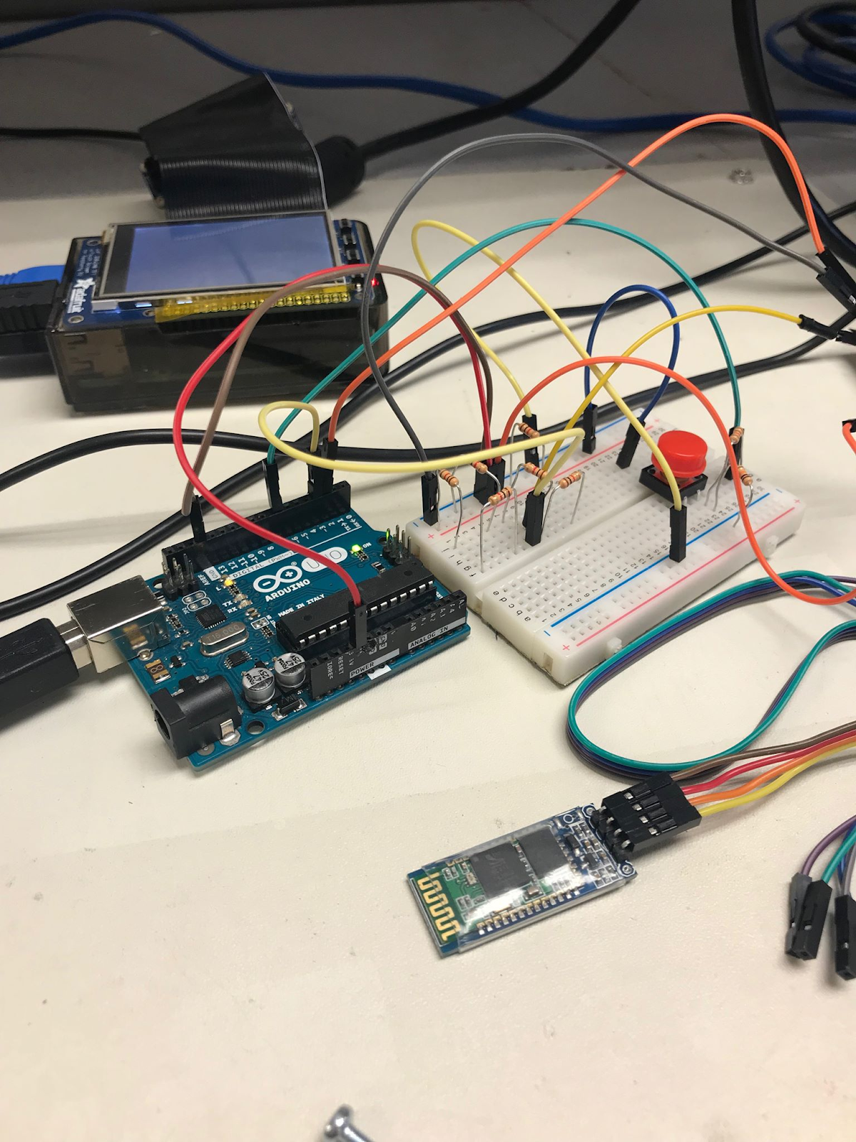
With our parts in, we put together a very simple prototype using an Arduino Uno which could read input from a few pushbuttons, and was connected via UART to the bluetooth module. We did not know how we needed to set up the bluetooth protocol, so we would just send different characters based on which button was being pressed or released. We were also able to send various configuration commands to the module, such as to change its display name.
We were able to have the Pi establish a connection to the bluetooth module, but RetroPie was not able to interpret any of the inputs. When we reached this obstacle, we began looking more into what we needed to change in order for the controller to register as a valid input. We discovered that our bluetooth modules, being very cheap, used the simplest type of bluetooth profile: serial. Game controllers fall into a category of bluetooth devices along with keyboards and mice called human input devices (HID). Our bluetooth module was not loaded with firmware that allowed us to change the profile to HID, but the actual chip on the module was the same as the one found on a different bluetooth module, the RN-42, which does have HID support. This meant that we could load different firmware onto our existing hardware to get it to behave the way we wanted.
Our first step in upgrading the firmware was breaking out the SPI lines from the chip, since these were not already accessible. We did this by carefully soldering wires to them.
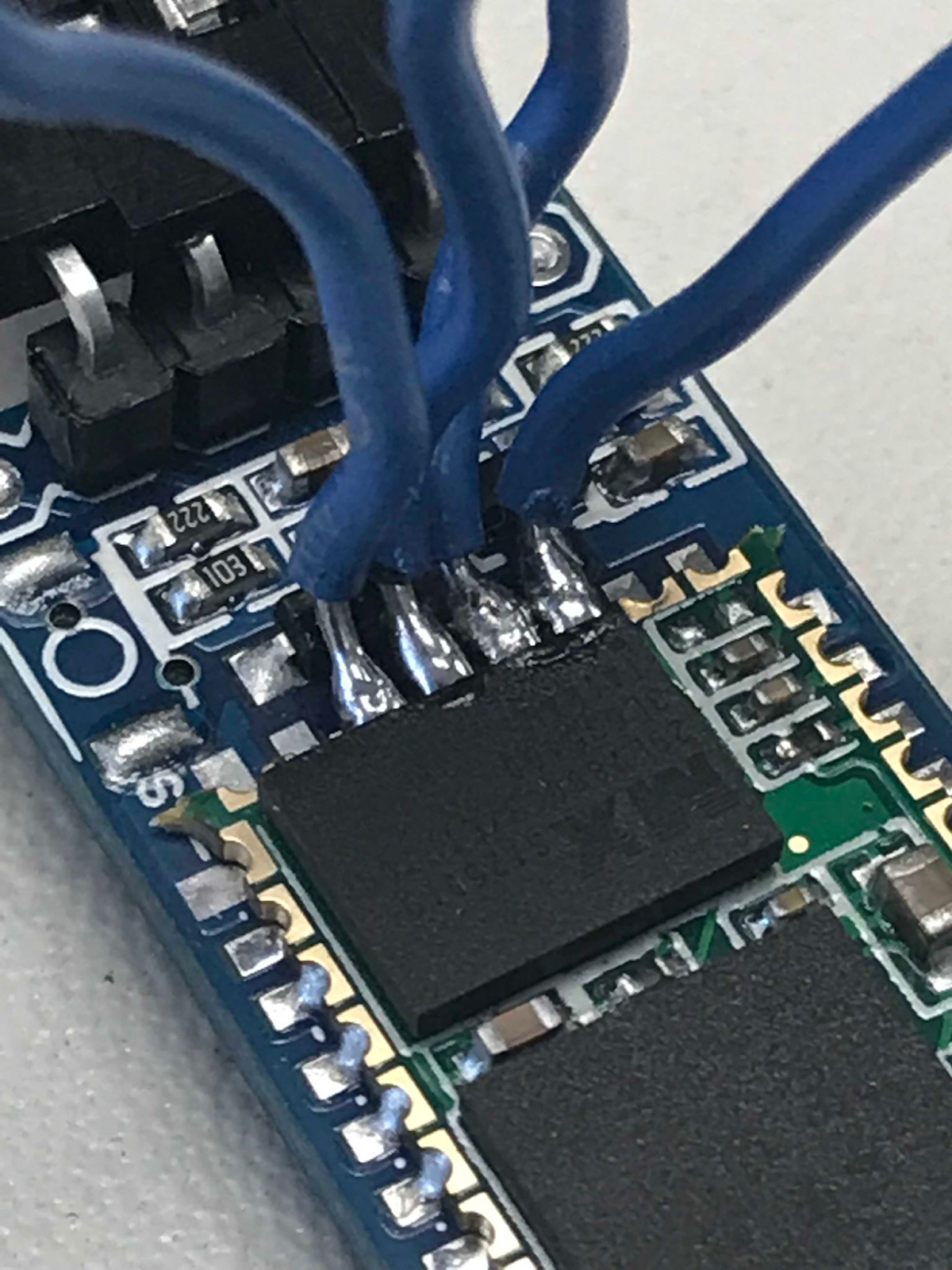
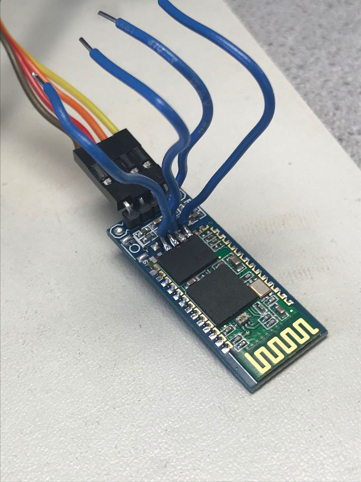
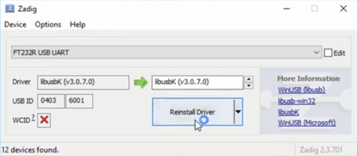
With the SPI lines from the chip now accessible, we were able to use a USB FTDI breakout to communicate with the bluetooth module using a laptop. RTS connected to CLK, RSD to MISO, RI to MOSI, and DTR to CSB. We also needed several software programs: BlueSuite, which contained several programs we used to change features of the bluetooth module, and Zadig, which was used to tweak the firmware on the FTDI to talk with the bluetooth module.
We had to modify one of the application files for BlueSuite, “usbspi.dll”, using a file from the FTDI driver to allow BlueSuite to work through the FTDI. We then used Zadig to change the FTDI firmware to “lubusbK (v3.0.7.0)”, which was necessary for it to communicate with the bluetooth module.
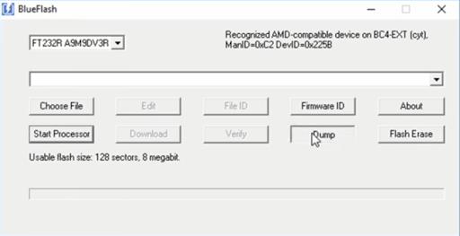
We then launched the BlueFlash tool, which was included in BlueSuite. This program communicates constantly with the bluetooth module through SPI, so we first tell the processor to stop, and then click the “dump” button to get a backup of all the firmware currently on the chip. In our case, this was the HC-06 firmware. Even though we will be replacing this with RN-42 firmware, it is still a good idea to have a backup in case anything goes wrong.
We then use the PSTool application, another program included in BlueSuite, to retrieve all the settings currently on the module. We select the SPI setting and choose the port that has our FTDI on it, and all the settings should appear. Once again, by clicking the “dump” button we are able to make a backup of all of this information. Maintaining some of these settings from the original module is actually critical, since even though we will be replacing most of it with settings for the RN-42, certain settings like the bluetooth address are unique to each chip, and must be copied over when we are adding the new settings.
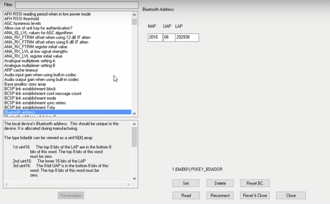
With all of these backups in place, we were able to get the new RN-42 firmware from a GitHub repository. Once the firmware file was downloaded, we opened it with BlueFlash and used the program to download it to the chip, replacing the firmware. We then needed to navigate to the backup dump we generated from the old settings. We only need to copy three of the settings: PSKEY_BDADDR, PSKEY_ANA_FTRIM, and PSKEY_ANA_FREQ. If we copy these three settings into a new text file, then the PSTools application has an option for us to “merge” these settings with the default settings. At this point, the new firmware was loaded, and the settings were set up so that the chip should be usable as a HID compliant module. When we connected it back into our test circuit with the Arduino, we were again able to use UART to give it several configuration commands, though now we had much more freedom in terms of what we were able to change. We referenced the command guide for the RN-42 to figure out what commands we had access to. In addition to changing the display name, we lowered the serial baud rate it used to talk with the Arduino, configured it to HID mode, and set it to behave as a gamepad. We also tested using it as a bluetooth keyboard, which allowed us to send text in the Arduino terminal and have it display on a connected iPhone.
At this point, we had our bluetooth module set up to appear as a game controller to other devices. The RN-42 manual (4) specified how the connected microcontroller should tell the bluetooth module the state of the buttons. It was simply a series of bytes each with different meaning. According to the command reference guide, the format was supposed to be:

However, empirically this was not the case. The first byte does not change, and indicates that the subsequent bytes are an update to the input states. The second byte is the payload length in bytes, which should always be six for the gamepad. The only difference we found was that the buttons were read from the last two payload bytes, not the first two. The X and Y bytes are supposed to indicate the positions of analog sticks.

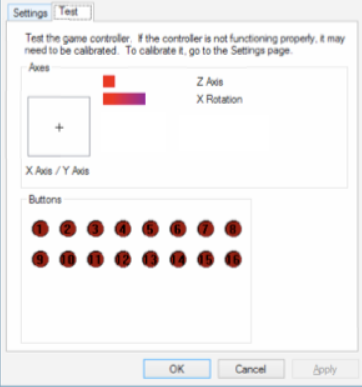
We were able to figure out this correct format by tweaking the code used by our Arduino prototype and connecting the controller via bluetooth to Alex’s laptop. Since it was now recognizable to Windows as a game controller, we were able to use the built-in utilities for configuring controllers to check whether our inputs were being interpreted correctly. To do this, we went to the controller’s settings, chose “Properties,” and chose the “Test” tab. On this tab, any actions registered would appear on the screen, showing us how the button was being registered (or if it was registering at all). After setting up the rest of the controller’s hardware, we tested the whole controller with this method. We used this tool to figure out the format of the byte stream being sent and fixed our code accordingly.
Once we had the payload format figured out, we were able to begin transitioning from our Arduino prototype to the more compact version using just the ATMEGA. The chips we ordered did not come preloaded with a bootloader, so we needed to burn this onto them. Luckily, Arduino provides a feature for doing exactly this. We accidentally ordered the ATMEGA328-PU instead of the ATMEGA328P-PU, but the chips are almost identical save for a few low-power features. This gave us some issues, but by modifying some of the Arduino IDE’s files we were able to trick it into treating the 328 the same as the 328P, and the bootloader worked just fine on it.
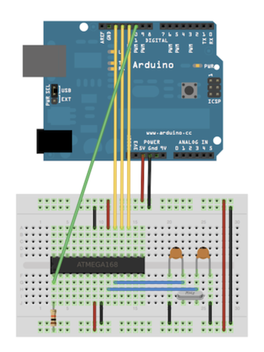
Once the bootloader was burned, we were able to begin loading programs onto the microcontroller. We had already returned the separate FTDI breakout we had borrowed for updating the bluetooth module, so we instead used the FTDI chip already included in the Arduino Uno. All we needed to do to access it was removed the ATMEGA from its socket in the Uno and connect the TX, RX, and reset lines to the ATMEGA. We started this process by setting it in a breadboard, along with the necessary crystal, capacitors, and resistors for basic operation.
Our final game controller code can be found in the Code Appendix below, but here we summarize the steps needed. First, we imported a built-in Arduino library called SoftwareSerial (reference #), which allows us to set up serial communication on other digital pins on the Arduino from the software. The purpose of this was to retain usage of the hardware serial pins in case we wanted to connect them to the console for debugging. We created an instance of the SoftwareSerial object, choosing pin 2 to be RX (receives serial data) and pin 3 to be TX (transmits serial data). We also initialized a uint8_t (unsigned byte) array of size eight to represent the byte stream to output whenever a button is pressed. The format of the byte stream was described above.
In setup(), we began our SoftwareSerial object (and serial monitor for debugging) at a baud rate of 9600 (115200 for initial configuration of the bluetooth module) and we set up our button pins and analog pins for the joystick as inputs, since the joystick was simply two potentiometers for the X and Y axes that we had to read. On our controllers, we used digital pins 5, 6, 7, and 8 for the buttons and A0 and A1 for the joystick. In loop(), we first reset the seventh byte of our stream/array, which represents the button pressed, to 0, effectively defaulting every button’s state to being not pressed. Then, we poll each of the buttons. If the input is high, we OR the byte with a 1 for the bit that represents that particular button (all of this was done in hexadecimal). This way, the byte can represent the state of eight buttons, which is enough for our controllers. To update the values for the third and fourth bytes, which represent the X and Y values of the joystick’s position, we read the values of the analog input pins, shifted the result right two times, and subtracted 128. The two right-shifts are used to convert the ten-bit analogRead() value into a byte, while the subtraction is used to effectively convert it into a signed value. Essentially, the initial analogRead() returns a value between 0 and 1023, and the right-shifts will yield a value between 0 and 255, but the bluetooth module expects values from -128 to 127, so we subtract 128 to produce the correct behavior. Finally, we communicate with the bluetooth module by transmitting each byte in succession. To configure the bluetooth module, we also added a couple of if-statements that say that if we’ve received any data from the module (such as an acknowledgement) on our software serial port, we print it out in the serial monitor, and if we’ve typed a command into the serial monitor, it gets sent to the module. This is used for configuration of the bluetooth module and debugging.
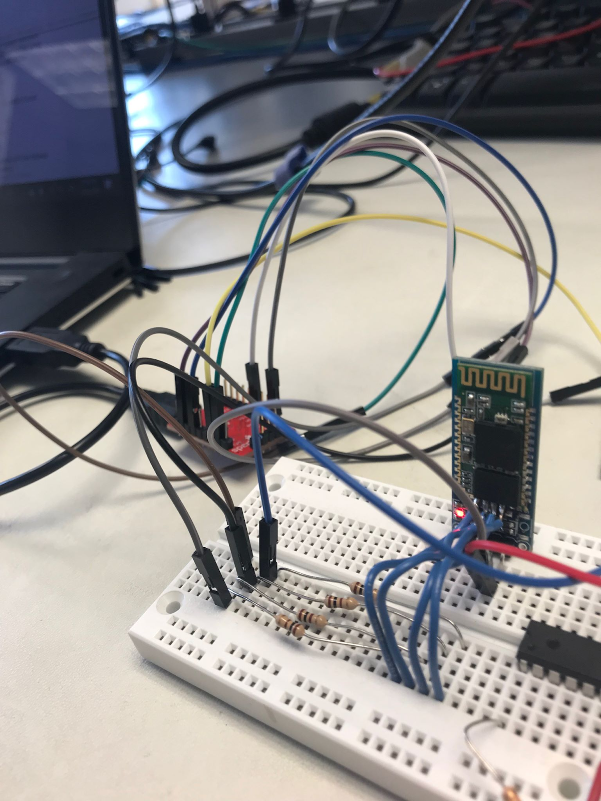
To connect the bluetooth module, its TX pin can be directly connected to our chosen RX pin on the Arduino because the bluetooth module outputs a 3.3V signal, which is enough to be read as high by the Arduino. The RX pin, on the other hand, has to be connected to the chosen TX Arduino pin through a voltage divider because the Arduino outputs at 5V whereas the RX pin on the bluetooth module only supports up to 3.3V. Our divider is therefore made up of a 2kΩ and 1kΩ resistor.
Once everything was working when connected to the laptop, we paired the controller with the Pi and tested it there. In EmulationStation, we went to the Bluetooth settings to search for devices to connect to. We found our controller easily (because we gave the bluetooth module a display name) and paired to it. Then, we followed the configuration prompts to set up our brand-new controller! These prompts allow us to assign each button and joystick movement a specific control, such as A, B, X, Y, etc. Once set, we were able to use our controller pretty smoothly, both to navigate the menu and in-game.
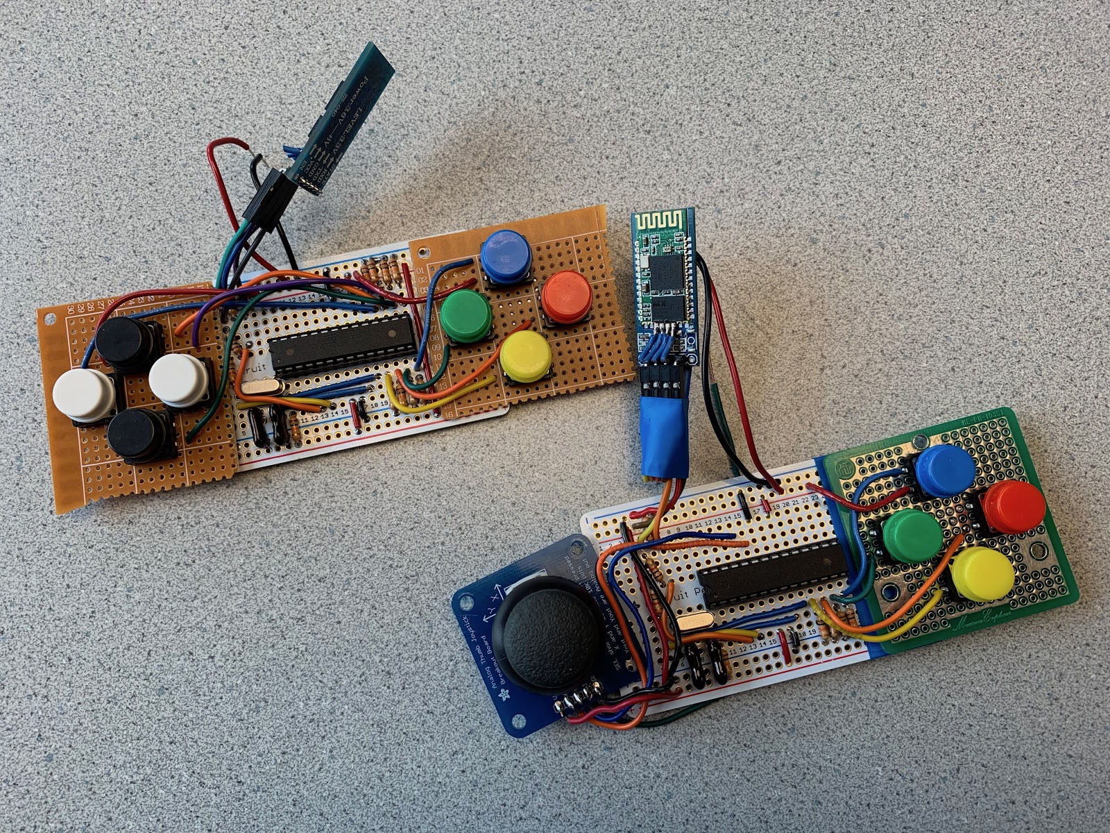
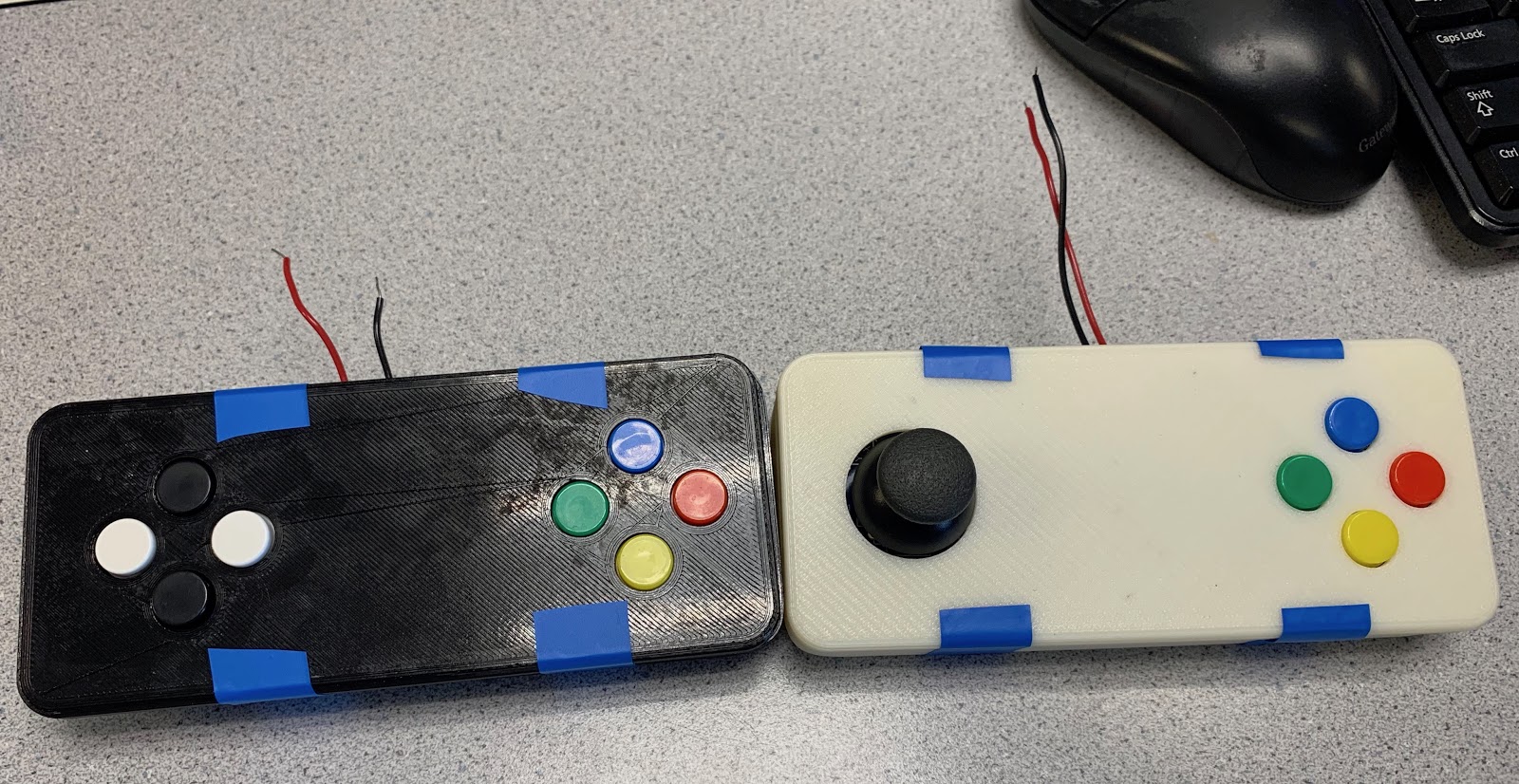
After finalizing our circuit design and our program, we programmed the ATmegas with the code and soldered the circuits to perfboards to make them more compact than the breadboard variants. Our results are below.
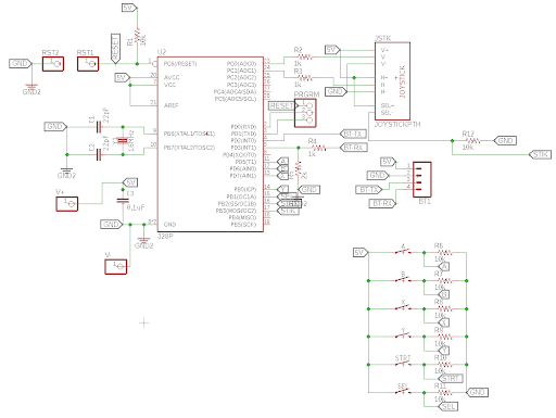
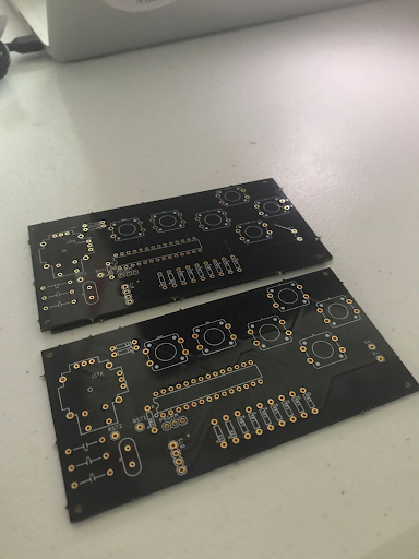
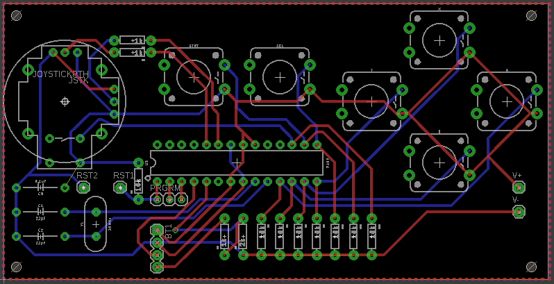
We also took the time to design and send out for a PCB that would connect all of the components. Unfortunately, the company experienced delays getting the boards back from the fabricator, and we did not receive them in time to include them in our final design. This would have allowed for sleeker, more compact controllers, but ultimately would not have changed the functionality. This did prevent us from including an analog stick on the second controller since the analog sticks could not be attached to a perfboard, and we only had one breakout board.
Kernel Configurations
On the Pi, we downloaded a fresh image of Retropie, which is built on Raspbian and incorporates software like EmulationStation and RetroArch. Below is a list of kernel configurations we made. Some were necessary to meet our goals and some were done just to make our project slightly more polished.
- In /boot/config.txt, we edited the line that said “hdmi_group = 2” to “hdmi_group = 1” in order for the computer monitor to support the resolution of the video output.
- To have the controllers auto-connect when the Pi boots up, we went to the Bluetooth settings in RetroPie and set up a udev rule for both controllers.
- To have the controllers auto-connect upon turning them off and on, we changed the bluetooth connect mode from “default” to “background.” These configurations allow users to just turn on the console and start playing without any controller set-up!
- Because the piTFT screen is very small, to make the text more legible we increased the font size. To do this we opened up the file containing the code for the default theme using
sudo nano /etc/emulationstation/themes/carbon/carbon.xmland changed every occurence of “fontSize” to 0.05. - Lastly, to make the system seem more polished, we followed instructions from RetroPie’s FAQ (11) to hide all of the boot text.
Results & Conclusions
Fortunately, everything that we were able to accomplish worked smoothly with minor issues, but we were unable to meet all of the goals we had originally planned based on our proposal. One remaining issue that we did not have time to solve was configuring the Pi to connect automatically with both of the controllers, from boot until power off. We got one of the controllers working (it connects to the Pi automatically on boot and even when we turn the controller off and on again), but after following the same configuration process for the second controller, it only connects on boot. Even so, connecting on boot allows us to avoid configuration of the controllers upon starting up the system, which is a nice feature we were able to add. The second issue we had was finding a way to power our controllers so that our whole system could be portable, but unfortunately we ran out of time to find a suitable power source, so we powered our controllers using an external power supply connected by long wires for the demo. This is not too big of a problem and can be easily solved given the right materials. As for powering the Pi, it can be done with a battery pack connected via USB.
Some goals that we had planned but did not meet include a larger (5”+) TFT LCD screen and switching to single-player mode by attaching the controllers to the sides of the main console. As we were looking for larger screens to replace our small 2.8” piTFT screen, we realized that we would either have to connect the new screen by HDMI, which would force us to disconnect the HDMI cable from the screen to an external monitor whenever we want to use a monitor, or to use a larger screen without HDMI, we would have to manually connect several wires between the TFT and Pi in a specific way (mapping GPIO into RGB colorspace, a pixel clock, VSYNC, HSYNC, etc.) or purchase a breakout board to simplify the complicated process. We decided that this would take too much time and money (breakout board + screen would probably go over budget) and that since the piTFT is functional and would allow us to use the HDMI port for the monitor, it would be sufficient for this project. Because we ended up using this small TFT screen, the console itself would not be big enough to support the attachment of our large controllers on the sides, and so we decided to keep the controllers separate from the gaming console. By the end of the project, we had not really touched the idea of how to combine two separate bluetooth controllers into one entity within the software, and after doing some research it looked to be complicated enough that we would not be able to accomplish this goal either. Our console still can be used in single player mode with one controller, but ideally we wanted to imitate the switch where both controllers combine into one large controller.
Even though there are some goals that were weren’t quite able to meet, we are still very proud of our project and everything that we accomplished! Our priority was to make something fun and multi-player, which is exactly what we did. We achieved a pretty much portable, compact, and embedded system that brings joy to all. :)
Future Work
If we had more time to work on our project, we would definitely strive to meet the other goals we had planned (larger screen, attaching controllers to console, using two controllers as one) and make our project a more complete, polished product. Outside of these original goals, we also think it would be cool to write our own simple two-player games in Python.
Work Distribution
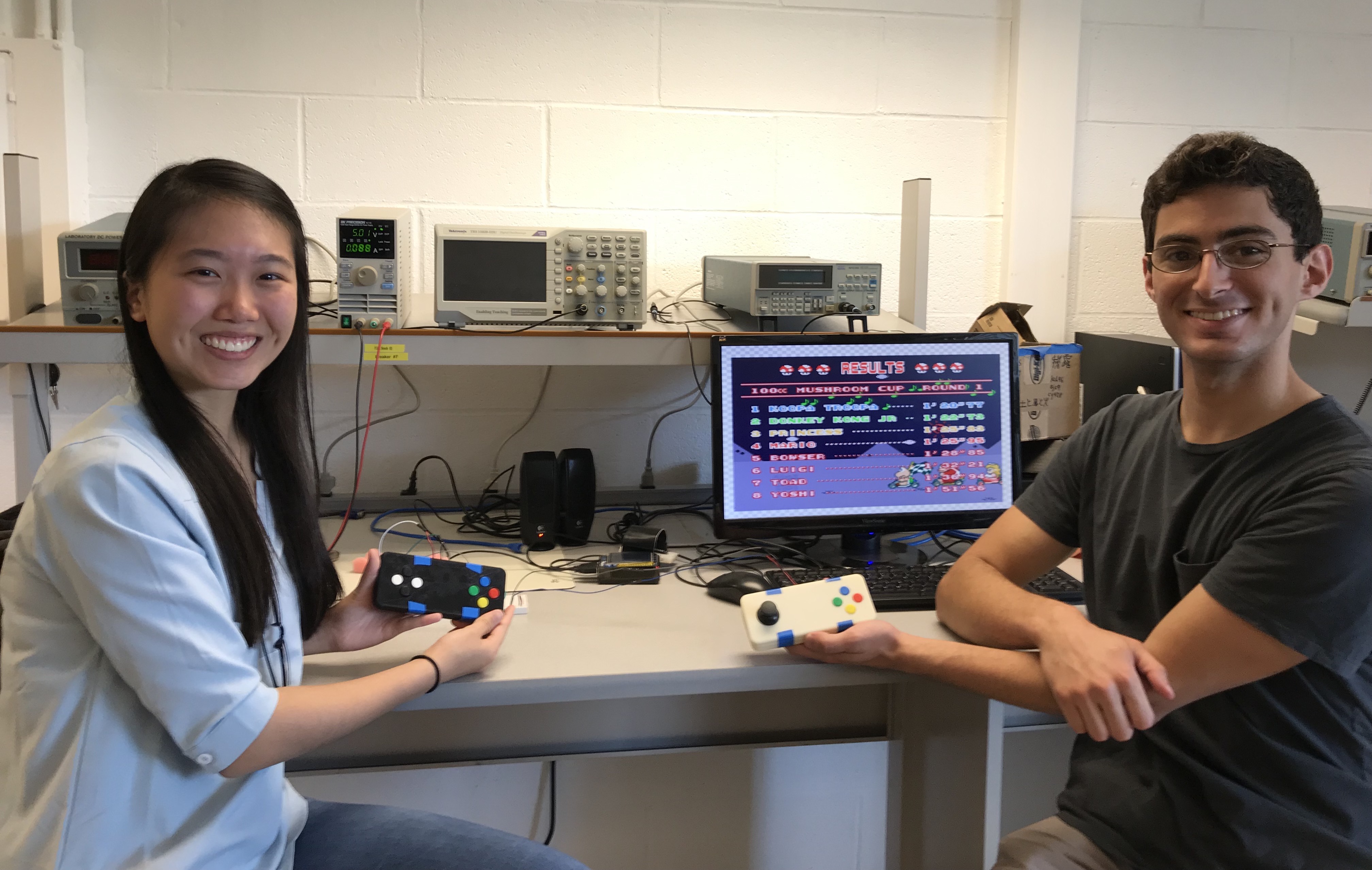
Us with our final project!

Glenna Zhang
glz6@cornell.edu
Configured kernel and Retropie. Found references and guides to help us develop solutions. Configured bluetooth modules and built controllers with Alex.

Alex Hatzis
ajh322@cornell.edu
Flashed new firmware onto bluetooth modules. Designed controller cases and PCBs. Configured bluetooth modules and built controllers with Glenna.
Parts List
| Part Name | Part Description | Site | Quantity | Unit Price | Total |
|---|---|---|---|---|---|
| JY-MCU HC-06 | Bluetooth Slave Module | Amazon | 2 | $7.99 | $15.98 |
| ATMEGA328-PU | Microcontroller | Digikey | 2 | $1.96 | $3.92 |
| ED281DT | Socket for ATMEGA | Digikey | 2 | $0.34 | $0.68 |
| COM-09032 | 2 Axis Joystick | Digikey | 2 | $3.95 | $7.90 |
| COM-10302 | Tactile Pushbuttons (Colorful) | Digikey | 1 | $5.85 | $5.85 |
| USB Battery (Easy 5V source) | Sparkfun | 2 | $8.95 | $17.90 | |
| ECS-160-20-4X | 16MHz Crystal | Digikey | 2 | $0.69 | $1.38 |
Total Cost: $53.61
References
- RetroPie download page
- Arduino tutorial on programming an ATmega
- Reference to set up auto-connect
- Guide to help us set up the bluetooth module as an HID gamepad
- RN-42 bluetooth manual
- Adafruit piTFT installer script
- RN-42 bluetooth manual
- Reference to help us get the HDMI working with small resolution
- List of video options
- Adafruit instructions on using installer script
- RetroPie set-up FAQ
- Adafruit reference to help us increase font size
- Arduino SoftwareSerial library
Code Appendix
GameController.ino
Controller software.
#include <SoftwareSerial.h>

#define A_BUTTON 7
#define B_BUTTON 8
#define X_BUTTON 5
#define Y_BUTTON 6

SoftwareSerial hc06(2,3);
int buttonstate;
void setup() {
  delay(1000);
  Serial.begin(9600);
  hc06.begin(9600);
  pinMode(A_BUTTON, INPUT);
  pinMode(A0, INPUT);
  pinMode(A1, INPUT);
}
// Format is:      Head   Len   X1    Y1   ZAX    XR    B1    B2
uint8_t bytes[] = {0xFD, 0x06, 0x00, 0x00, 0x00, 0x00, 0x00, 0x00};

void loop() {
  delay(100);
  bytes[6] = 0x00;
  if(digitalRead(A_BUTTON) == HIGH) {
    bytes[6] |= 0x01;
    Serial.println("A");
  }
  if(digitalRead(B_BUTTON) == HIGH) {
    bytes[6] |= 0x02;
    Serial.println("B");
  }
  if(digitalRead(X_BUTTON) == HIGH) {
    bytes[6] |= 0x04;
    Serial.println("X");
  }
  if(digitalRead(Y_BUTTON) == HIGH) {
    bytes[6] |= 0x08;
    Serial.println("Y");
  }


  bytes[2] = (analogRead(A0)>>2)-128;
  bytes[3] = (analogRead(A1)>>2)-128;

  hc06.write((byte)bytes[0]);
  hc06.write((byte)bytes[1]);
  hc06.write((byte)bytes[2]);
  hc06.write((byte)bytes[3]);
  hc06.write((byte)bytes[4]);
  hc06.write((byte)bytes[5]);
  hc06.write((byte)bytes[6]);
  hc06.write((byte)bytes[7]);

  if (hc06.available()){
    Serial.write(hc06.read());
  }
  if(Serial.available()){
    hc06.write(Serial.read());
  }
}