Laser 3D Scanner
Michael Xiao (mfx2) & Thomas Scavella (tbs47)
ECE 5725: Embedded OS, Spring 2019, 5/14/19
Demonstration Video
Introduction
The Laser Scanner is a Raspberry Pi embedded system device able to digitize objects into .obj mesh files for reproduction using 3D printing. The device does this by utilizing a line laser and the PiCam to perform computer vision. The laser is positioned 45 degrees askew from the laser and projects a bright red line on one vertical slice of the object. The camera detects the slice’s distance from the center to give a mesh slice. The object is spun on the rotating tray and the process is repeated until the full object is scanned. The generated .obj file is finally emailed to the user.
Project Objectives:
- Accurately scan small objects
- Create an embedded system that would be easy to use for the user
High Level Design
We drew a lot of inspiration for this project from our past experience with 3D printing and rapid prototyping. Being able to scan existing objects quickly can make them easy to reproduce and design other parts around as well. When we looked to the internet to see the cost of these scanners, we saw that they were often quite expensive. With our background in computer graphics, embedded systems, and mechanical design, we decided that this was a feasible and interesting project for our team to take on.
The central component in this design is the line laser that projects upon a vertical slice of the objects. This projection could be captured on the picamera, have its perspective corrected, and then filtered prior to image processing. In image processing, the distance between each segment of the line from the center of the object could be collected. In radial coordinates, this picture would yield both the r and z components. The third dimension, Θ, is then achieved by rotating the object to a new slice. This concept is shown in figure 1.
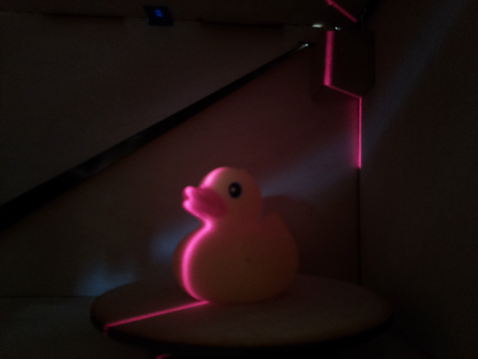
Figure 1: Laser scanning concept
To perform the described actions above, we utilized a Raspberry Pi as our central computing unit. We attached a stepper motor and a motor driver to the Pi, powered by an external 5V supply and controlled by the Pi’s GPIO pins. A line laser was put on the 3.3 V line on the Pi and a PiCam was attached to the camera input on the Pi. Lastly, a simple pulled down button was installed and a status LED to indicate to the user what state the system is in The full system is summarized in figure 2.
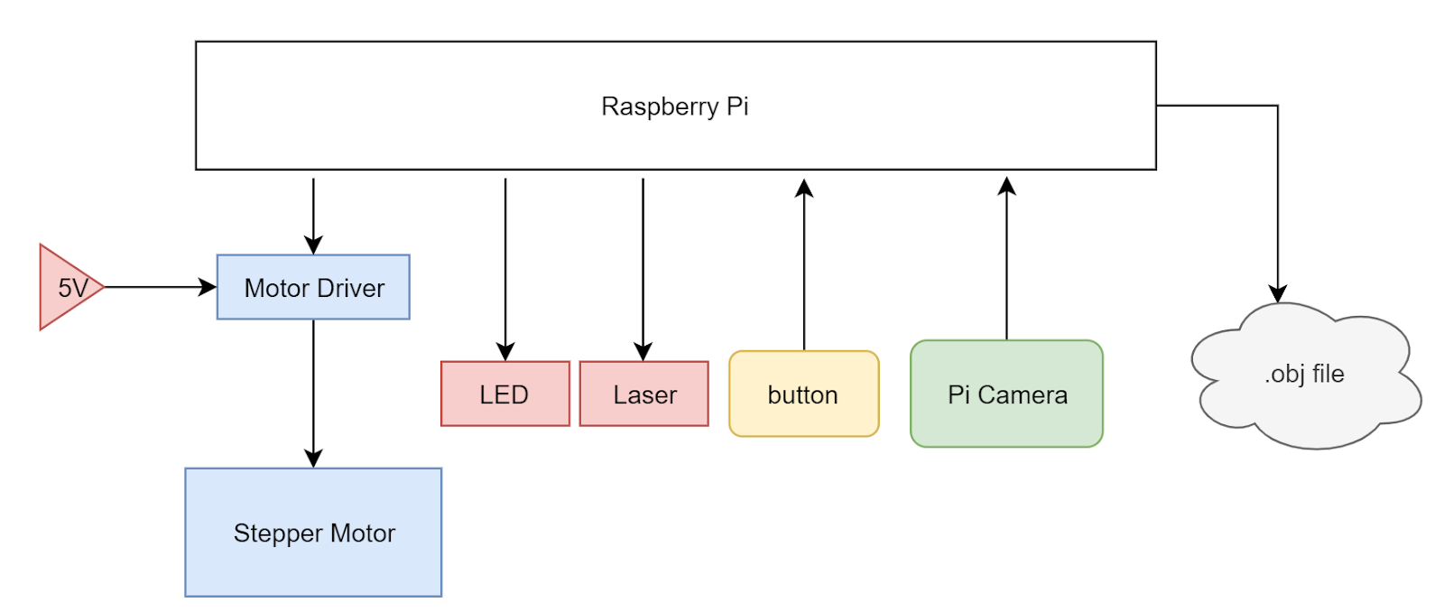
Figure 2: System block diagram
These pieces were housed in a sleek laser cut box held together with T joint M3 machine screws with a hinged lid. The electronics are hidden from sight in a bottom compartment and the lid allows for easy access to object placement on the rotating tray. This lid is necessary in order to minimize the amount of light that leaks into the system, as this external light can produce noise in the final scan.
Hardware
As seen below, before we began laser cutting or 3D printing, we used Autodesk Fusion 360 to make a detailed 3D model of our design. As an overview, the device is a simple box with a lid with laser cut hinges. There are two main layers of the device, the electronics bed and the main bed, with holes for wires to run between the two layers. The assembled CAD file can be seen in figure 3. The main parts we used included the Raspberry Pi, the line laser, the stepper motor, a stepper motor driver, the PiCam, a metal push button, an LED, and raw material for laser cutting and 3D printing. A detailed bill of materials can be found in the appendix.
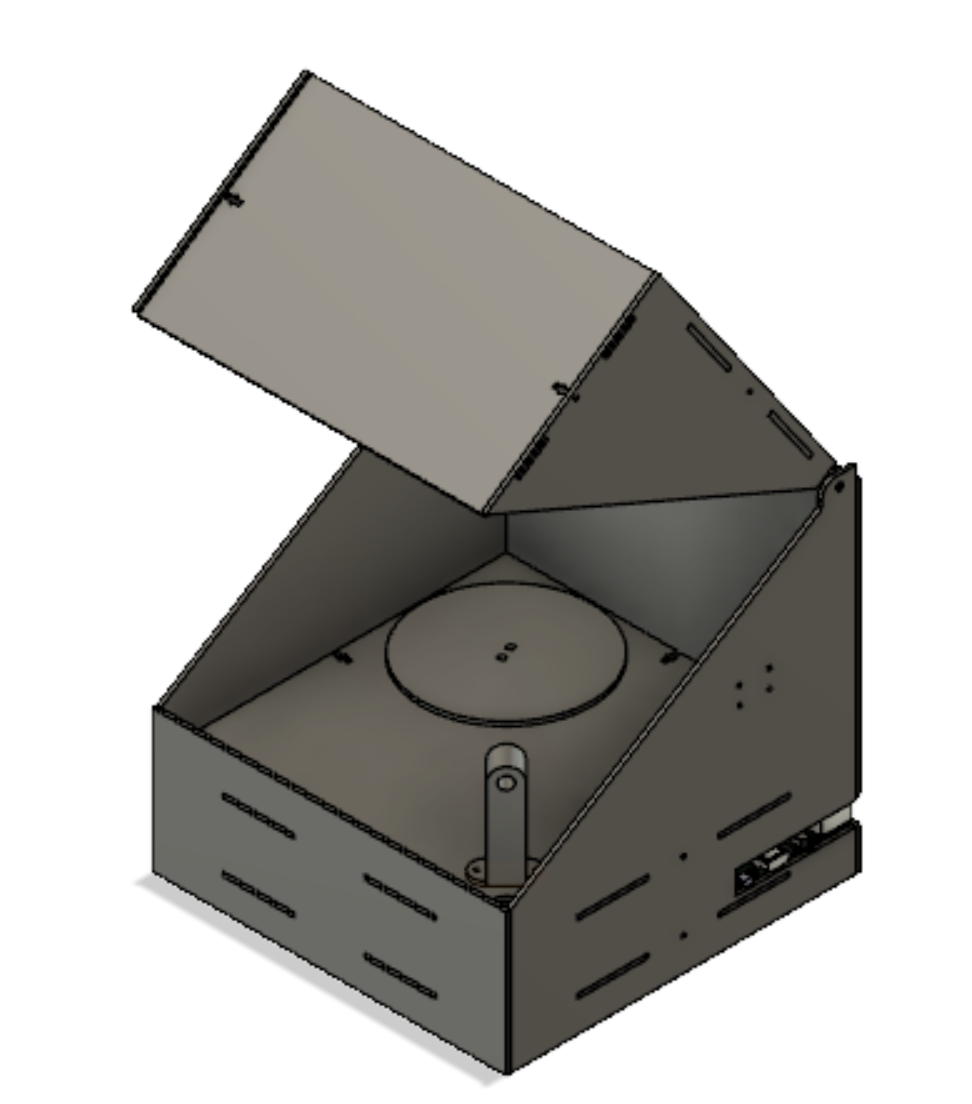
Figure 3: CAD Prototype
The wiring hardware of this project was very simple as the 3D scanner did not require too many peripherals. As shown in figure 4, we were sure to connect resistors in series with each pin we used in order to protect the pins from shorts. One GPIO pin was dedicated to controlling the status LED, which would light up when the device was ready to be used and pulse with PWM when the device was operating. Another GPIO pin was connected to a pulled-up button, registering HIGH when the button was not pressed and LOW when the button was pressed. Lastly, we dedicated four GPIO pins to driving the stepper motor.
Since our motor only had to step a certain extent without requiring control of speed, we opted for a simpler stepper motor driver (L298N) that simply steps up the control lines to feed into the motor’s inputs. To learn about how to operate the stepper motors on a very low level, we referred to both the L298N data sheet and the Arduino library. Stepper motor’s have a magnetic core with pertruding fingers of alternating polarity. The four wires are wrapped to control two electromagnets which each power every other opposing finger in the motor. Thus, by switching the polarity of the fingers, we are able to push the stepper one step. With this knowledge of how steppers worked from a hardware level, we were able to control the steppers much more easily. We opted to power our stepper motor off of a 5V power supply in the lab rather than the Pi because of its maximum current draw of about 0.8 A, which is more than the Pi could supply.
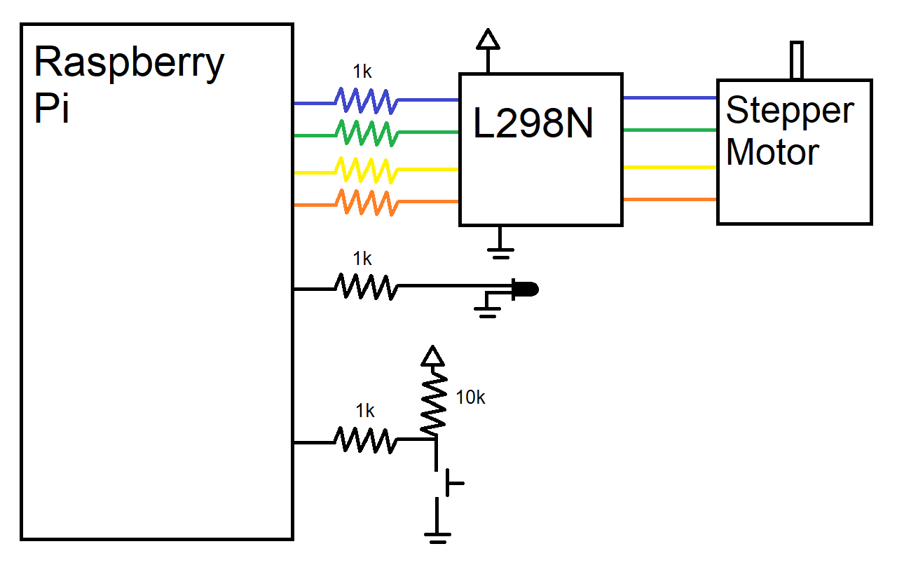
Figure 4: WIring Diagram to the Pi’s GPIO pins
As seen in prior pictures, the majority of our box was manufactured with a laser cut, with designs being produced in Fusion 360 and cut using CorelDraw on an Epilog Zing 40 W laser cutter. Our designs are shown in figure 5. From top left moving right, the pieces are the main bed, the electronics bed, two pieces for the lid, the back piece, the front piece, and the two side pieces. In the main bed, there are three main cutouts: one for mounting the stepper motor, one to route wires from the laser, and one to route the PiCam’s wide cable. The bed piece has mounting holes for securing the Pi, breadboard, and motor driver and a larger cutout to access the stepper motor. The lid pieces snap together simply to form the triangular piece seen above and the hinge is a simple extrusion that is the width of the diameter of the hole of the side boards. The back piece and one of the side pieces have slots on the side so that the ports of the Pi (HDMI, USB, Ethernet, Power) can be accessed easily. The front is a simple piece that we eventually made holes in with a hand drill to mount the button and LED.
As seen on all the pieces, our parts are held together by M3 hardware using T-Joints and slots. This is a method of holding laser cut pieces orthogonally and securely. The fins of pieces line up with the slots other pieces and the t-shaped cut on the edges give space for an M3 nut to be jammed into them without spinning. This allows us to then use an M3 screw to lock the pieces together with very wiggle room.
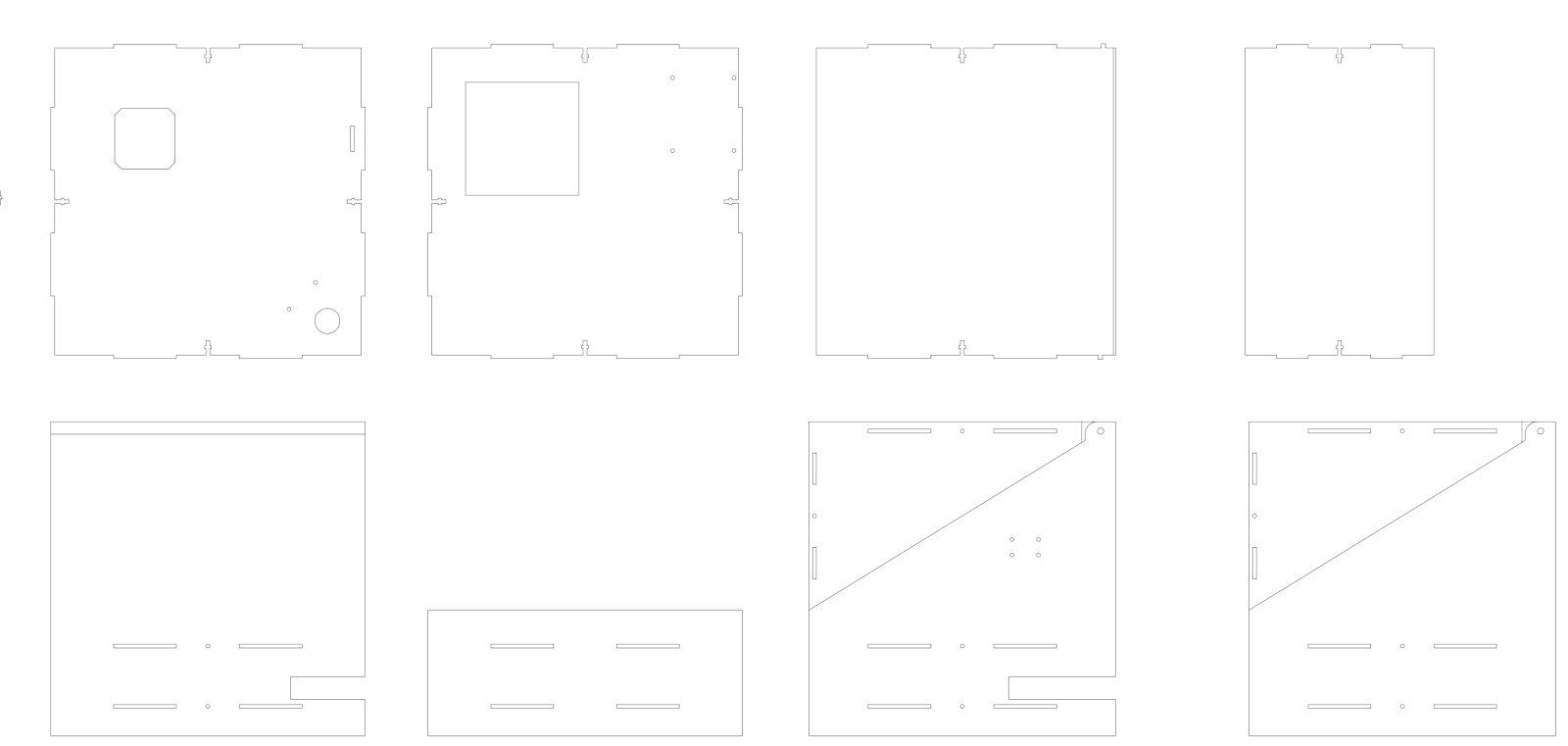
Figure 5: Laser cut pieces
We chose to do the majority of our pieces with a laser cutter due to its speed and ease. However, we still had to 3D print some pieces due to their 3D geometry that would be more difficult to create on the cutter. THe first piece was the line laser holder. This piece was to be mounted on the main bed at 45 degrees from the camera’s view and have a hole such that the laser could be snuggly friction fit into it. We also had to create a motor mount because the motor’s shaft was so long. The mount friction fit into the laser cut pieces and lowered the plane that the motor was attached to such that the rotating platform was flush with the main bed. These pieces are shown below in figure 6.
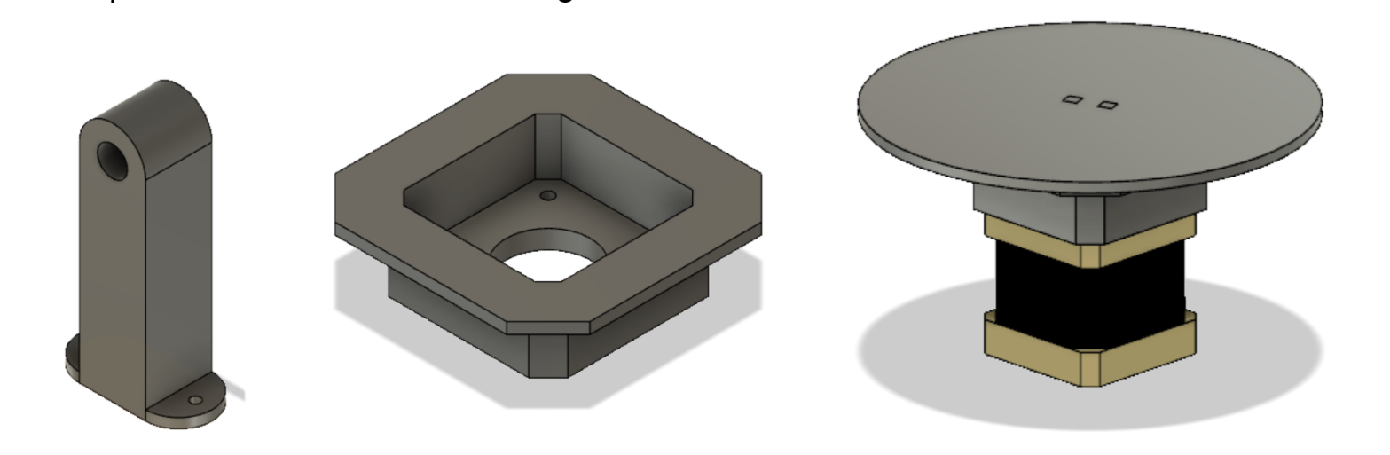
Figure 6: (a) line laser holder (b) stepper motor holder (c) assembled stepper motor mounting with the rotating wheel
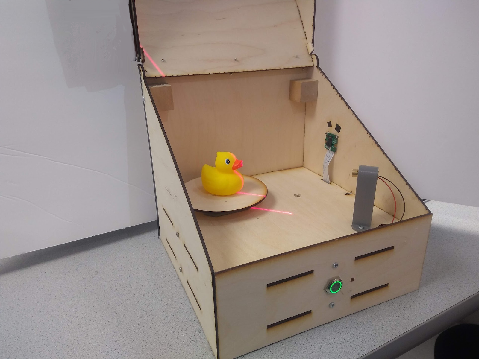
After manufacturing and assembly, our 3D scanner’s hardware was complete and we were ready to tackle the software half of the project. Figure 7 shows various features of the hardware design.
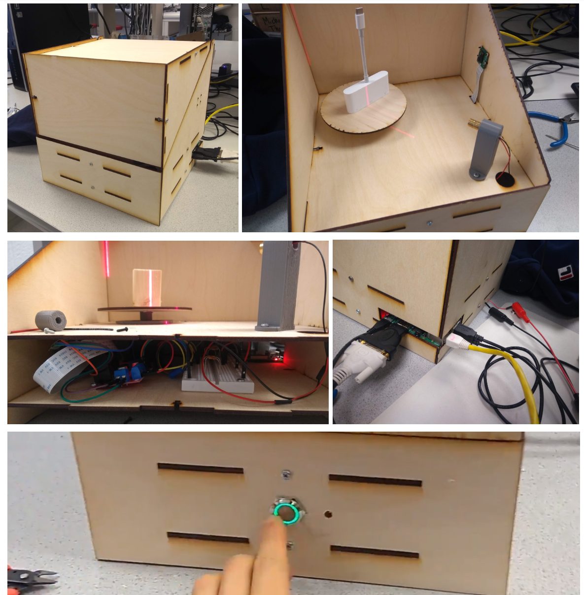
Figure 7: (a) assembled box outside (b) assembled box inside with camera and laser (c) inside view of electronics bed (d) back of the Pi with access to Pi ports and the 5V motor input (e) push button with LED ring and status light in the front of the device
Software
The software for this project can be broken down into four main components that interact together: Image Processing, Motor Control, Mesh Creation, and Embedded Functions.
As a summary of the software, we can look to figure 8. As the system boots, the .bashrc automatically logs into the Pi and starts running our python code. The system lights up the status light to let the user know that it has been booted correctly and waits for the button press. The user can then place the item to be scanned and close the lid. After pushing the button, the LED pulses to let the user know the device is working. The device will loop between image processing and motor control until the full rotation is complete and all object data is collected. Finally, the mesh is created and the file is emailed over to a preselected email. This restarts the cycle and the machine is ready to perform another scan at the press of a button.
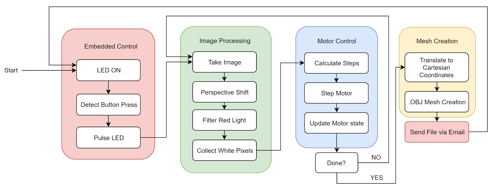
Figure 8: Software block diagram
Image processing
The first thing we implemented was processing a captured image in order to extract the information stored in the image into a form that could be used to create an array of points in space. To do this, we started by taking a picture of the object on the platform along with all the background noise created by the laser shining onto the back of the box and dispersing. This picture had two main problems in its raw form. First, the object was viewed at an angle with an elevated perspective and second, there was a lot of background noise. The first thing we needed to do was account for this viewing angle because using the photo as is would not allow us to determine a consistent object height. As seen in figure 9, the height of the upside down “L” shape is consistent; however due to one side being longer than the other they appear to have different heights at the edge closest to the viewer.
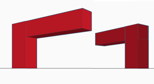
Figure 9: The effect of perspective on relative height
To fix this, we had to transform the workspace in the image into a rectangle from the trapezoidal shape it was in previously. To do this, we used the code provided by reference 2, which when given an image and four points, crops the image between the four points and transforms the cropped image to compensate for the perspective. This transformation uses the four points to create a rectangle instead of a trapezoid type shape as seen in Figure 10.
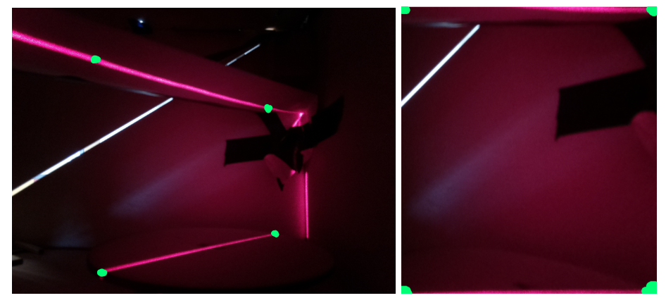
Figure 10 (a): Workspace before transformation, (b): Workspace after transformation.
The next problem that needed to be solved was that of background noise in the form of outside light and light being reflected by the laser itself. To do this we filtered the light using the inRange() function of OpenCV. We set the threshold to only pick up red light at a certain level. To get the correct value, we started with a lenient threshold and kept increasing the threshold level until the only light being picked up was the laser light on the object being scanned.
Once we had this image we found the brightest pixel in each row to get a line of one pixel per row that bordered the left most side of the laser line. Each pixel was then converted to a vertex in 3D space and stored in an array, as described in the mesh creation section. The results of these steps can be seen in figure 11.
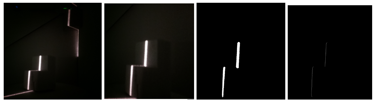
Figure 11 (a): The raw image.(b): The raw image transformed to account for the perspective of the camera (c): The transformed image after background noise is filtered out.(d): The final image with only one white pixel per row.
Motor Control
After being able to successfully process a single image to get the slice of the object, we needed to be able to rotate the object to take a new picture with a different angle. To do this, we controlled the stepper motor below the platform that the object being scanned sits on. We built a foundation of our stepping function from the reference code mentioned in our appendix. The code essentially continuously tracks the state of the motor and where the fingers described in the hardware sections are located. This is key to stepping and microstepping. Microstepping essentially gives us the option to perform half steps, doubling our steps per rotation from 200 to 400.
The motor is stepped by simply altering which of the motor pins are high and which are low. We made a step function that takes the input of how many microsteps to move the stepper motor and the current state of the motor. It then moves the motor accordingly and also outputs the new state. We had a simple int variable in python to globally record the state. The state variable took 8 different values representing the 8 states, as described in table 1.
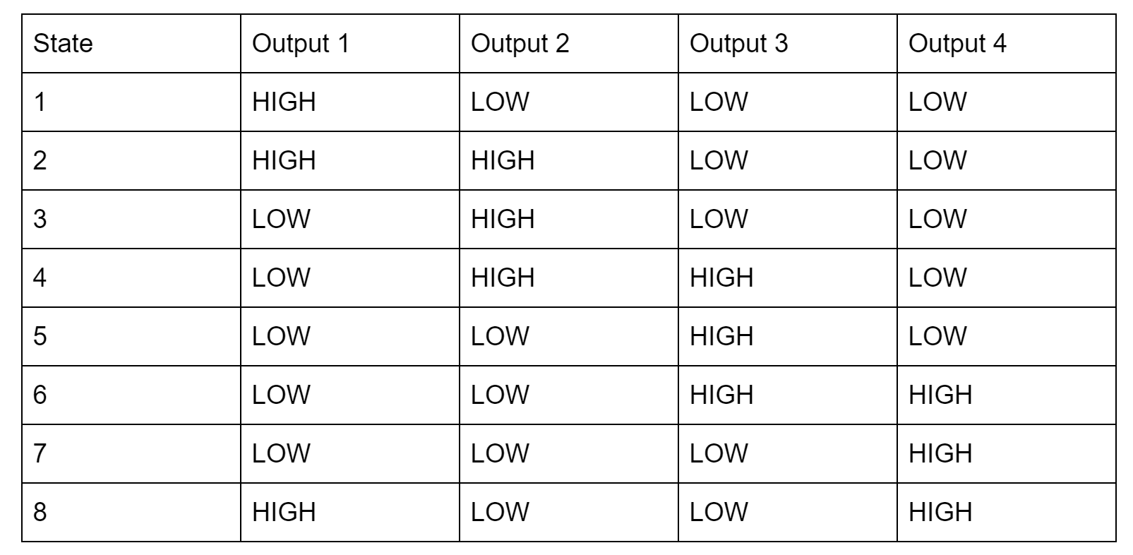
Table 1: Stepper motor states and GPIO outputs
Once we had this step function, we called it each time our system was ready to take a new picture. In order to determine how many steps the motor should take each turn we needed to know the desired number of photos for the scan, or the resolution about the rotational axis. Knowing this, and that to complete a 360 rotation the motor would have to take 400 micro steps, we found the desired number of micro steps by dividing 400 by the angular resolution. This angular resolution could be changed in the software depending on how accurate of a scan you need and how quickly you want to scan the object.
Mesh Creation
To create a mesh from all the processed images, we first had to convert each white pixel in the processed image into a vertex in 3D space. Because we are collecting individual slices of the object with cylindrical symmetry, it made sense to start to collect cylindrical coordinates. This made sense as the height of the picture could represent the z-axis, the distance from the center of the rotating table could represent the R-axis, and the rotation of the stepper motor could represent the theta-axis. However, because we stored our data in cylindrical coordinates, we had to convert each of these vertices over into cartesian coordinates. This is shown in figure 12.
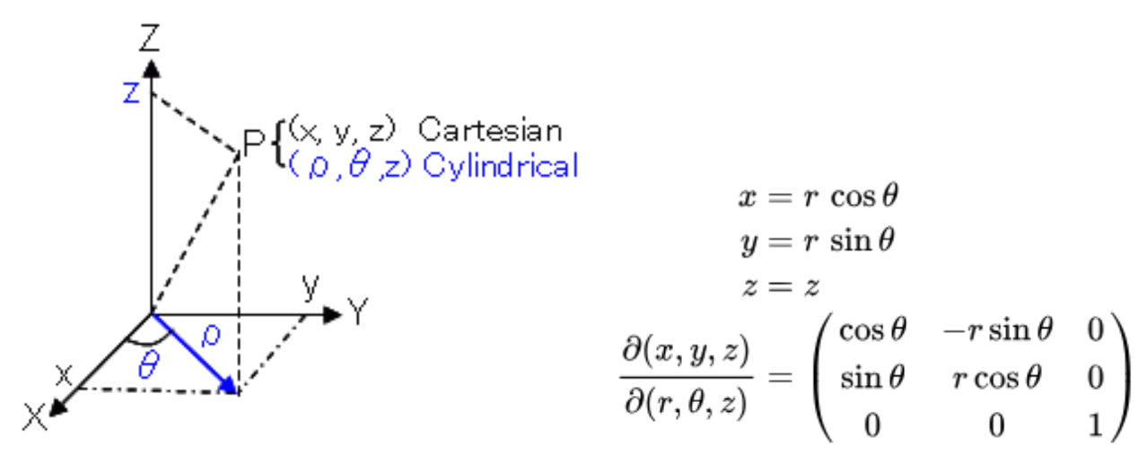
Figure 12: Visualisation of cylindrical coordinates and the conversion algorithm
Once these vertices were created they were stored in a list and said list was stored in another list that contained the vertex lists created for each image captured. Once all the images were processed and converted to vertices, we had to select the vertices that we actually wanted represented in the final mesh. We wanted the top vertex and the bottom vertex to be included and then based on the resolution we picked an evenly spaced number of vertices to use for each image. Because not all vertex lists were of the same length, we had to even them out by finding the list with the smallest number of vertices and removing vertices from all other lists until they were all even.
With the vertex lists created we were now able to create a mesh. We chose to format our mesh by the .obj file standard as it is simple and 3D printable. A .obj file consists of four parts, the positional coordinates, the texture coordinates, the face normals, and the faces. However, to keep things simple we did not provide the file with any texture coordinates or face normals as we didn’t have any textures and most 3D mesh viewers assign basic normals if not told otherwise. For the position coordinates, the format is: v a b c, where a is the x coordinate, b is the y coordinate, and c is the z coordinate. Each positional coordinate in use is listed in this manner in the beginning of the file. Under the positional coordinates are the faces. For the faces, the format is: f a b c, where a is the index of the first positional coordinate of the face, b is the second, and c is the third. Convention states that when looking at a face from the outside, coordinates are labeled in clockwise order. For example, the .obj file with the following text:
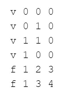
Would create a square mesh in the x-y plane with the points (0,0), (0,1), (1,1), and (1,0) as its corners. To create a mesh in this way, we went through each vertex list and created faces connecting the current vertex list to the previous vertex list. The challenge with this was that, in order to make the mesh file as small as possible, we had to make sure we did not write any unnecessary positional coordinates to the file. To do this we had to keep track of the index of a vertex in the .obj file if we would need it to create a face later. This was especially important when making the final faces that connected the last vertex list to the first vertex list. Once this was done the .obj file was ready to be viewed or sent.
Embedded Function
After our device was functional, we polished it by adding full embedded functionality. This meant removing the keyboard, mouse, and monitor, and having it wirelessly send us the .obj file after finishing processing. To start, we changed the .bashrc code as described in lab 3 to automatically log in and launch the main python program on startup. This was done by using sudo raspi-config and selecting “Console Autologin” and by adding the line “sudo python /home/pi/finalProject/FINAL.py” to /home/pi/.bashrc.
In addition to this, we also added a button and status LED for user input and output. The button would let the user tell the device when to start scanning and the LED would tell the user the state of the machine. If the LED is on, the device is ready to start a new scan. If the LED is pulsing, the device is currently scanning. If the LED is office, there is a software error, calling for a system restart. To implement these functions, we found the gpiozero library very helpful. We defined pins for the Button and the PWMLED (GPIO 23 and 18 respectively) and used the built in functions. We used a simple polling while loop to wait for the button to be pressed and a pulse() funcion on the LED that would slowly alter its PWM pulse width to simulate a pulsing LED.
Lastly, we enabled the device to send the .obj file over email. This was done by using the smtplib and email libraries. We built a foundation for our code using Sam Lopez’s example framework cited in the appendix and wrote a function to send the file to an email. We then created a dummy email account for our pi to use (5725pi@gmail.com) and gave the login credentials to the program. A MIME (Multipurpose Internet Mail Extensions) email object was constructed and a subject line, message, and attachment were appended. Next, a SMTP (simple mail transfer protocol) server was created and the login credentials for our pi’s email was used to login. This MIME object was transported through the account on the server to be sent to any email with the 3d.obj file attached. This ability to send emails gave us a very convenient and wireless way to deliver the produced file to the user to access on many different platforms.
Results
As seen in figures 13 and 14, the laser 3D scanner was able to scan objects with decent precision. The objects’ features are distinct and recognizable and the parts were very easy to 3D print using a slicing software such as Repetier. Figure 13 shows one of our first scans we tried and the 3D printed result from the scan.
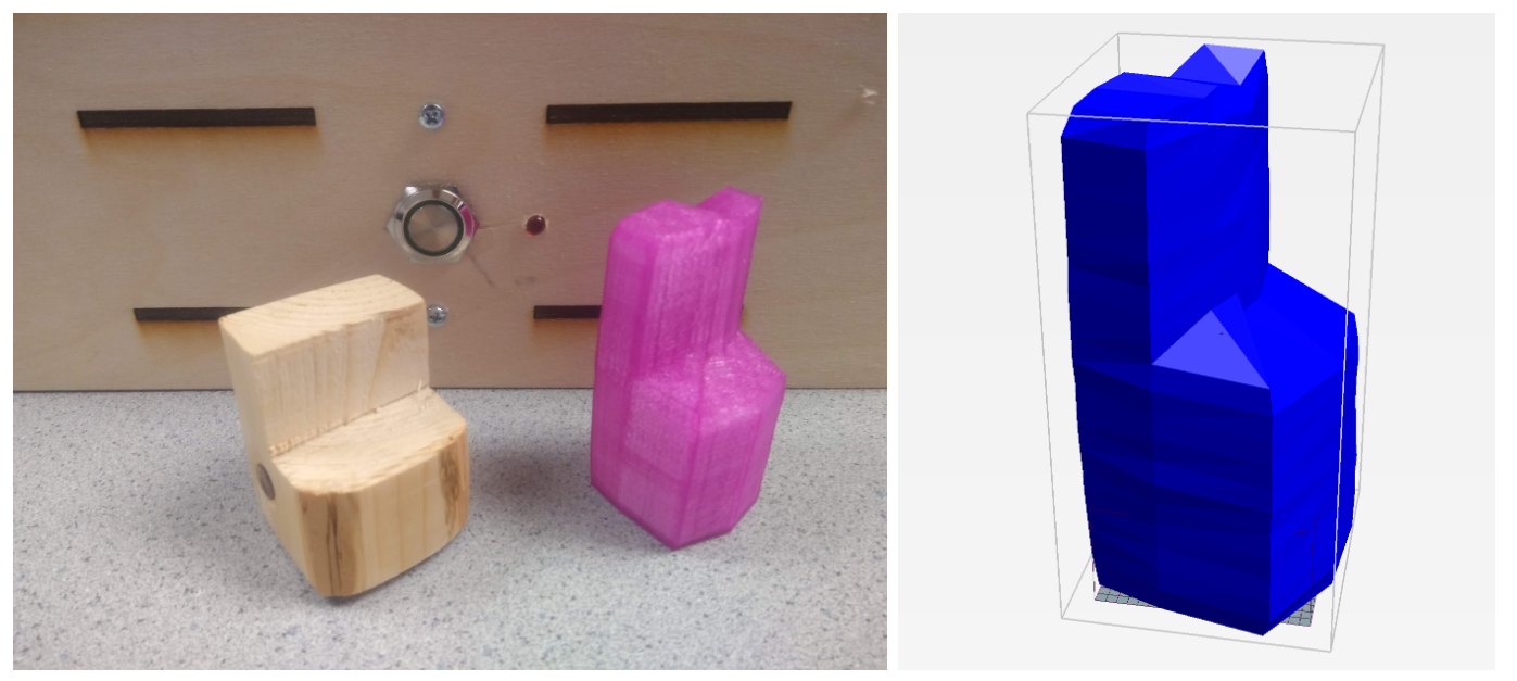
Figure 13: Wooden chair original piece, scanned .obj file, and 3D printed recreation
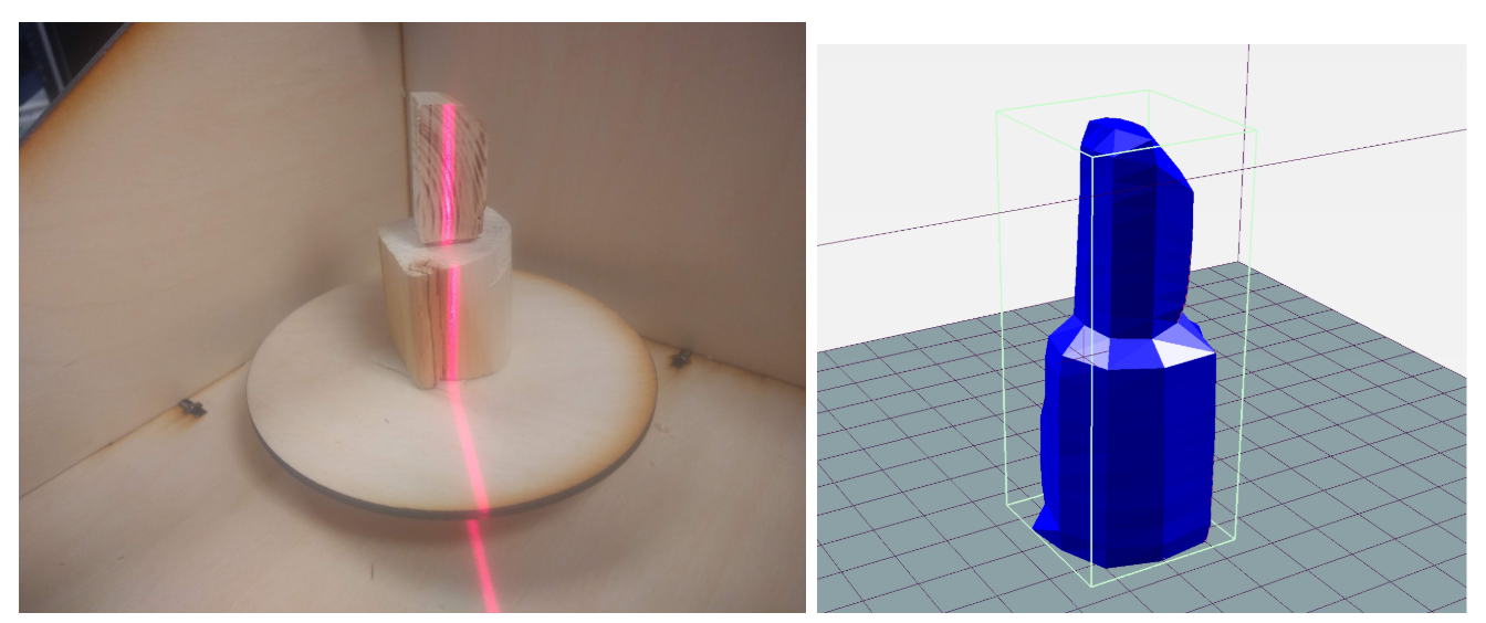
Figure 14: Stacked wood blocks and .obj scan
After successfully scanning many simpler objects, we tried to scan some more complex objects as well. We chose to try a rubber ducky as we had found one laying around. We were able to successfully capture the features of the duck in our scan as shown in figure 15.
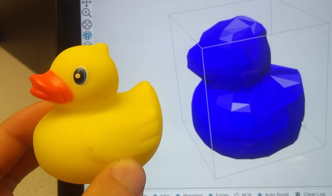
Figure 15: Rubber ducky and .obj scan
One of our biggest findings and successes that we discovered during testing was the consistency of the device. Throughout multiple trials of the same object, the scanner was able to produce a .obj file that was very very similar each time, even if we slightly altered the placement of the object. This can be shown in figure 16. As seen in the three separate scans, they all look very similar, capturing the same details and same amount of detail. We were overall very impressed with our system’s consistency and robustness.
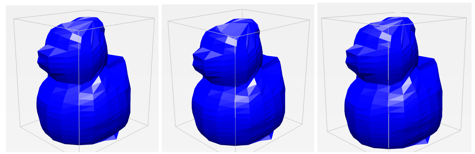
Figure 16: Three separate scans of a rubber duck
One of the variables we are really able to tune is the resolution of the scans. Because we have 400 steps in the stepper, we can choose how big each ΔΘ to dictate the angular resolution. By default, we have the angular resolution set to 20 iterations, meaning that each frame, the motor rotates by 20 steps (400/20 = 20). This was chosen mainly in the interest of time - it takes about 45 seconds to complete a scan this way. However, if we want a much higher quality scan, we can increase the number of iterations all the way up to 400. This gives us many more points to construct the model with, making for a much more detailed scan. In addition to angular resolution, we can also adjust the vertical resolution, or how many different points we choose to poll along the laser slice. For a similar interest in time, we have this default set to 20 but we can increase it for better results. In playing with these parameters of angular resolution and spatial resolution, we were able to compile the results of different scans below in figure 17. Each label is formatted such that it is the angular resolution x spatial resolution. As seen in 17b, the default scanning settings, the features of the duck are recognizable but not detailed. However, as we increase the resolution, individual precise features begin to show, including the eyes, beak, tail, and wings on the duck. The highest resolution image took about 5 minutes to scan. Seeing this high of an achievable resolution was a very large success.
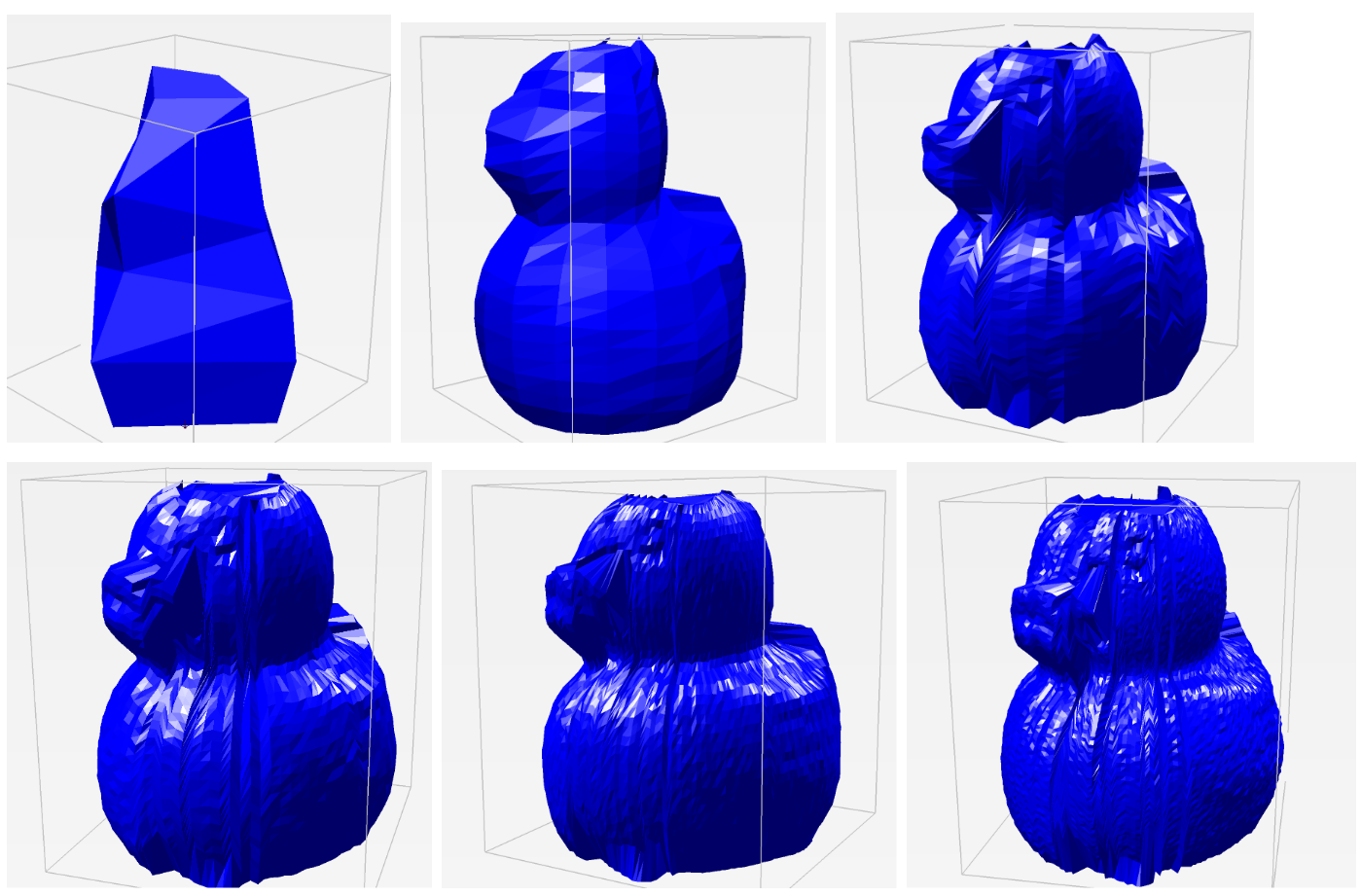
Figure 17: (a) 4x4 resolution (b) 20x20 resolution (c) 50x40 resolution (d) 100x40 resolution (e) 200x 40 resolution (f) 200x80 resolution
Limitations
Despite the successful results of the project, there are still a few limitations of our design and implementation. With the use of the laser comes a lot of issues with how the light disperses. Many objects we tried to scan that were either translucent, shiny, or very dark proved troublesome with how the light reflected off the surface. If the object was translucent, the light would be absorbed and dispersed, making for a very noisy reading of slices. In shiny and dark objects, the light would either be reflected or be absorbed to the point of which it would be difficult to pick up. Furthermore, because we are using a camera to capture the features of objects, its sensing is limited by its line of sight, meaning that concave objects and sharp angles are often blocked by other parts of the object. This is shown in our rubber duck example as the tail sometimes will lose its curvature in the scan. The camera can also only detect surface structures meaning that holes or internal geometries cannot be captured. However, this is a common problem that many other scanning solutions have as well.
Conclusion
Although we were happy with the results of our project, there were a few things that could be implemented to make it better. For starters, in the current state, the scan resolution can only be changed by changing the hard coded resolution variables in our code. To make our project more embedded, we could create a resolution potentiometer so that we could change the resolution without having to plug in a monitor and keyboard to the scanner. In addition, our scanner creates images that can sometimes look jagged. To fix this, we could look into mesh smoothing techniques that would be applied to our finished mesh in order to smooth out irregularities and harsh corners. On top of this we noticed that sometimes our imaging filtering process would not work perfectly, and strange outlier points would be added to the mesh. To address this problem, we could look into filtering the white pixels based on the surrounding pixels so that outliers would not be included in the final mesh. Lastly, we found that pixel coordinates do not scale well into the real world. The meshes we created were 6 to 7 times larger than the actual object. In the future it would be advantageous to implement a way of scaling our meshes so they are more accurate to the real size of the object.
Overall though, we learned a great deal from our project and had fun building the system. From using the PiCamera to controlling a stepper motor to image processing to sending emails, we were able to overcome a diverse number of unique obstacles and apply our knowledge and learnings to solve these problems and create a successful device. We are quite proud of the scan quality the laser 3D scanner can achieve and want to look into implementing some of these ideas for future work.
Appendix
Work Distribution
Mechanical Design: Michael
Circuit Design: Michael & Thomas
Image filtering: Michael & Thomas
Mesh modeling: Thomas
Wireless communication: Michael & Thomas
Final Report: Michael & Thomas
Parts List
- Raspberry Pi $35.00
- Raspberry Pi Camera V2 $15.00
- LEDs, Resistors and Wires - Provided in lab
- 3D printing filament - Provided
- 12x12x0.125 wood sheets - Provided
- M3 Mounting hardware - Provided in lab
- Stepper Motor - $18
- Line Laser - $8
- Stepper Motor Drivers - $9
- Metal Pushbutton - $5
Total: $91
References
PiCamera DocumentEmailing with Python
Perspective Transform in Python
Stepper Motor
Viewing OBJ files
Sample Scanned OBJ files
3D printed chairduck 10x10
duck 20x20
duck 50x40
duck 100x40
duck 200x40
duck 200x80