Dimensioning Robot
May 18, 2018
Project By Audrey Fuhr (aef99) and Roanja Milo (rm692).
Demonstration Video
Introduction
Our team built and programmed a robot to measure and calculate the dimensions of a 3-D object. The robot is first initialized with an interface to learn information about the object, such as if it has a circular or rectangular cross-section. Then, the robot moves around the object and maintains a constant distance from it until it returns to the starting position. Post-processing allows an x-y plot to be created as well as calculations such as cross-sectional area to be saved to a folder.
This project had many successful components. The frame and mechanical components such as encoders were functioning in the robot. The robot was able to move around an object and maintain a constant distance, yet the motion is not entirely smooth. Furthermore, the robot did not always stop at the correct position after moving around the object, so a manual end button was created. Post processing was successful with accurate calculations and plots created, even with the challenges that occurred in this step.
Project Objective:
Create a robot that can determine the dimensions of a three dimensional object. This robot will need to make use of sensors or a camera to help it move around the object. To track the length of the object, it should maintain a constant distance from the object and recall the starting location and the location of its every step know when it has been around the object.
Mechanical Design:
The mechanical design used the components given in Lab 3. This included the plastic base of the robot, two wheels, and a servo for each wheel. We used a Raspberry Pi 3 which was powered by a power bank. We used PWM signals to control the speed and direction the wheels were moving. A battery pack with 4 AA batteries was added to power the servos. We utilized an encoder wheel print out like the one shown. It has black and white sections, which the encoder uses to differentiate between.
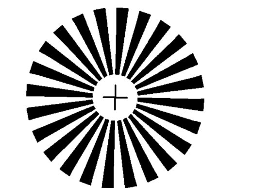
Figure 1: Wheel Encoder Black and White Spokes
We connected two encoders, each close to and facing a wheel, to allow processing of the motion of the robot. The encoders were screwed onto the motor frame, to be approximately 2 cm from the wheels. We encountered an issue with one of our encoders which was temprementally working, so we had to use one 15cm encoder and one 10cm encoder. We resolved this issue by placing the 15 cm encoder further from the wheel.
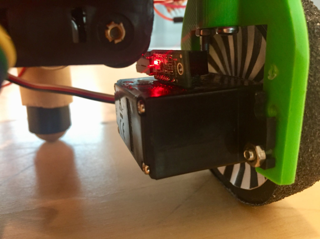
Figure 2: 15 cm rotary encoder mounted to motor observing wheel rotation
We mounted an ultrasound sensor to the front left of the robot, to measure the distance of the robot to the object being measured. The location of the mount was chosen to be close to the front of the robot. We believed this be the ideal location for it because it determines if the robot needs to turn, and allows the wheels, which were further back, to have enough time to turn.
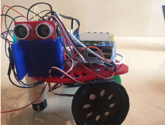
Figure 3: Sonar mounted on front and left side of the robot
Software and Post-Processing
We used modular code blocks by first organizing our code into various functions for each of our components so that we could test certain components if anything seemed to fail. We implemented an encoders.py, sonar.py, motion.py and finally a final.py script, which incorporated code from the other three scripts. We began by coding the optical encoders. The encoders used callbacks, so each time either the left or right encoder was triggered, there was an interrupt, which raised the total count of ticks on both the left and right wheels. We implemented a right count and a left count variable to keep track of the total ticks each of the wheels traversed. Our encoders are guided by the following code:
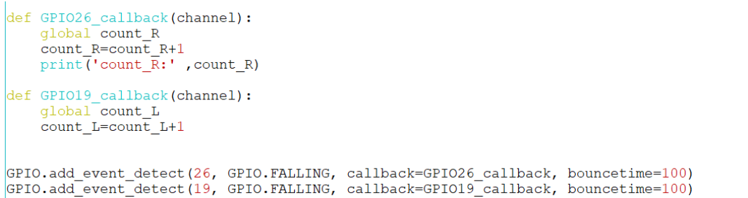
Figure 4: Encoder call-back function
Sonars were used to guide the robots motion. The sonar logic allows the robot to maintain a certain distance from any object. If the object is within a set distance, the robot goes straight. If the object distance falls below 10 cm, the robot turns left, otherwise it turns right. This code worked well for motion around a circle, however it was not great for motion around rectangular cross sections. This was due to the sharp 90 degree turns, which caused the robot to occasionally run into the wall. Therefore we implemented an option where a rectangular shape could be analyzed. The logic for this is based on if the sonar does not detect an object for multiple iterations, indicating a sharp turn, it would turn more smoothly. The sonar was set up using the trig and echo functions.
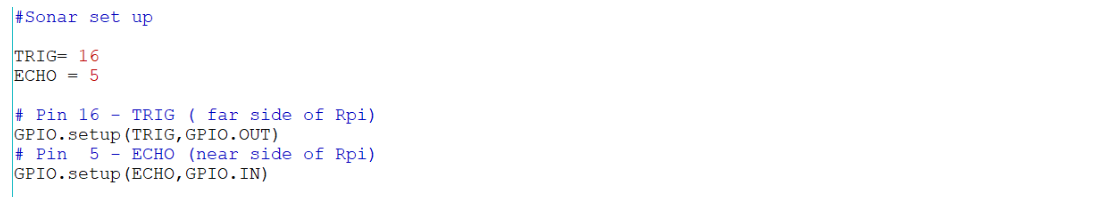
Figure 5: Sonar set up
The key aspects of this project were to be able to determine the global coordinates of the robot at all times, so that it has knowledge of where it begins and where it ends. The only information we use to determine this is the number of ticks that are triggered on each wheel in a given time. The global coordinates (global x and y from the starting reference frame) are acquired by implementing frame rotations at each time step. The following logic was used:
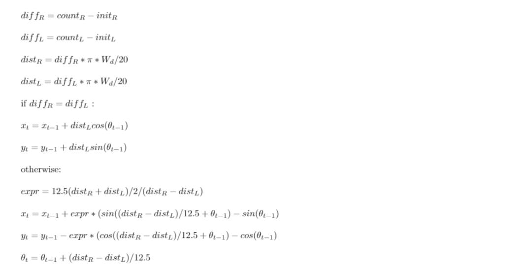
Figure 6: Logic for determining global x, y and theta
The difference in counts within the 0.2 s interval are defined as diff_L and diff_R. Distance travelled in that time are then computed as dist_L and dist_R using the wheel diameter and the number of spokes of 20. In the case that the difference in spokes between the left and right wheel are the same, we know the robot has travelled in a straight path. Otherwise we know that it has turned. If it has turned, arc length equations are used to determine the x and y positions. From the x and y coordinates, the area of the shape is then be computed using the following equation:
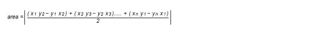
Figure 7: Area formula obtained from coordinates of a polygon
Using this information with the x, y, and theta arrays, post-processing was then completed. After the robot has returned to its initial position, the post-processing interface appears on the piTFT screen. One option is to view the calculations that have been completed. Clicking this button allows the user to see the area (in cm^2). We found this by using the arrays with the x, y, and theta values. Since the robot is moving about 10 cm from the object, we took this into account to find the area of the object itself. Furthermore, for a circular object, we found the radius using the equation: A=(pi)*r^2 where A is the area found and r is the radius. For a rectangular object, the length and width are found using the difference of the max and min values calculated for the x and y coordinates respectively.
Another button on the post-processing screen allows for the user to view the x-y plot that the robot traversed. This is created using the matplotlib library.
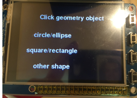
Figure 8: Geometry screen options
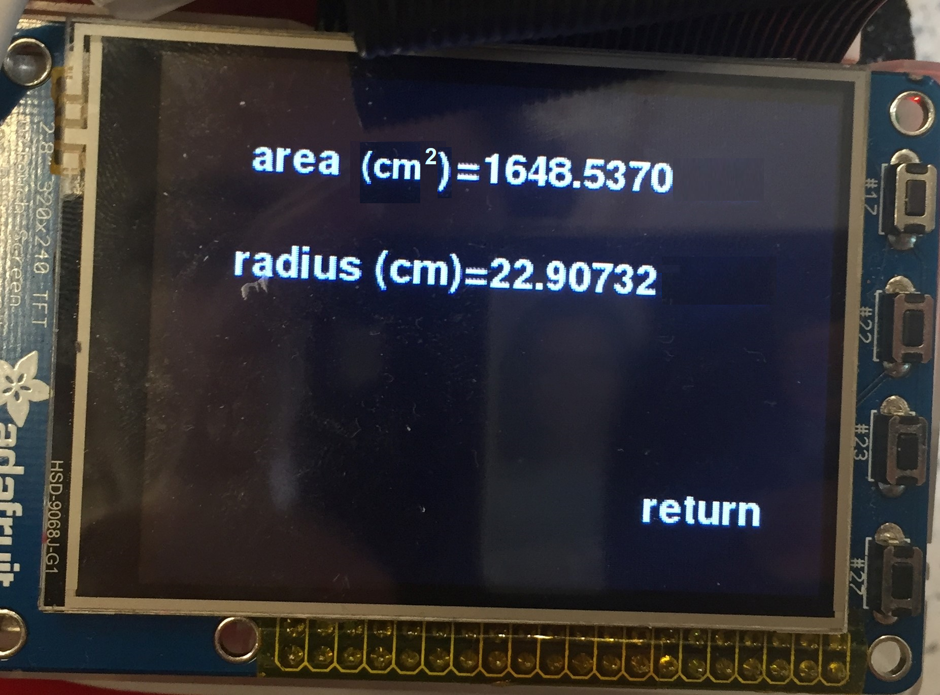
Figure 9: Area and radius display screen
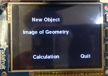
Figure 10: Final screen displaying options for viewing geometry or selecting new object>
Testing
To begin, we tested each component of our hardware and software individually with a base code or oscilloscope.
The motion of the robot’s wheels were tested using a seperate code. This allowed the robot to move in a relatively straight path with the wheels moving at similar speeds. It also helped to find the optimal speed of the wheels during straight and turning motions, by finding frequencies and duty cycle for each wheel and direction of motion.
Furthermore, we tested the sensor at several steps of the design process. We first tested the sensor separately by placing objects at given distances and measuring the calculated values. Once the robot’s wheels were working and the code to move the robot was added, we tested how the robot moved around different objects. We observed if the motion was smooth around the object, and if it was maintaining a consistent distance to the object. Once challenge was for objects with sharp corners such as rectangular objects because the sensor would initially turn too soon and become too close to the object on the next surface. Therefore, we added code to detect edges such as this and react appropriately.
Properly placing the encoders was a challenge in this project because these encoders needed to be placed at a very specific angle and position in relation to the wheels. Initially, we placed the encoders at an arbitrary distance and position near each wheel. Once the robot and code were first completed, we were able to detect errors in the measurements of the encoders to set distances actually travelled by the robot. One fix was to paste printed images to the wheels to allow it to detect more rising and falling edges than just using the spokes of the wheels. Then, we used an oscilloscope to help with the placement of the encoders. The encoder position was optimized by placing them where the signal from turning the wheels at a constant speed created very symmetrical and consistent signals, as found with visual inspection using the oscilloscope. This placement was then tested with the robot moving about 50cm and the results were much more accurate. Testing the encoders was a major part of the testing completed for this project due to the degree of accuracy needed.This shows that a re-design might be necessary to ensure the encoders cannot be shifted.
To test the robot and its accuracy in measuring dimensions, we tested a rectangular and cylindrical object primarily that had specific measurements. This allowed the team to work initially in constrained and optimal conditions. This testing involved running the code many times to see if the robot would move accurately, stop in the starting position, and post-process the information correctly.
Results
The robot is successful in moving as intended, stopping at the initial position, and measuring the dimensions of the cross-section of a 3-dimensional object. Work could be completed to optimize these results to give less error, such as tightening the tolerance of motion of the robot, and adding another sensor to the system.
The final deliverables of the robot include mapping out the traveled path in addition to providing information about the shape that it had traversed. For example it provides the area of the cross section of shapes. Data was saved as images of the traversed path by the robot. The following figure shows a successful iteration of the robot moving around a cylinder with a radius of approximately 40 cm.
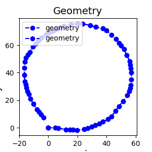
Figure 11: Successful iteration of robot motion around a circle of radius 40 cm. >
There were some issues that arose during demo including possible discalibrations of the encoders or temporary hardware malfunctions. At one point there was a random malfunction which caused the odometry to act up. The following image was supposed to represent the odometry of the robot traveling around a circle.
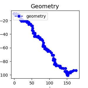
Figure 12: Unsuccessful iteration of robot motion around a circle of radius 40 cm.>
Conclusion
Our robot was successful in implementing encoders to track the robots location as it traversed along a path. We learned that encoders are useful and accurate for determining both the distance our robot moved in addition to its location from its beginning reference frame. We learned that the placement of the encoders is very important, however if correct placement is achieved and kept in a stable position, the encoders will work reliably.
We were able to learn how to design an embedded operating system in a big picture scope in addition to learning how to implement various electrical, mechanical and software components.
In summary, even though there were challenges, we are very satisfied with the results of our dimensioning robot. It has useful applications that could be used in real systems.
Future Work
There are many future steps that could be added to add functionalities to the robot. For example, the robot could be optimized to run at a faster speed. Additionally, the robot could measure the height of the object to allow the height and volume of the object to be displayed. This step could be implemented using a camera that would detect the change in depth and therefore be able to determine the height of an object. Another method to determining height could be to use a standard rotation motor with an ultrasound sensor. Once the ultrasound sensor does not see the object, it will know that it has reached the height of the object. Using a camera, the object could be programmed to measure several objects in a row, and compare them.
Work Distribution

Roanja Milo
rm692@cornell.edu
Focus on implementation of encoder and sonar.

Audrey Fuhr
aef99@cornell.edu
Focus on processing of data and interface.
Audrey Contribution
- Mechanical build of robot
- Motion of robot using sensor and processing coordinates using encoders
- Processing of coordinates
- Post-processing code
- Website design
Roanja Contribution
- Encoder implementation
- Mechanical build of robot
- Electrical/wiring set up of encoders, sonar, bi-directional voltage converter, and motors
- Post-processing code
- Motion of robot using sensor and processing coordinates using encoders