Autonomous Nerf with Stereo Vision
Jonah Okike-Hephzibah (jo356) and Anshuman Das (ad765)
May 18, 2018
Demonstration Video
Project Objectives:
- Design a robotic device capable moving to desired orientations using inverse kinematics.
- Create a system with two cameras, capable of obtaining depth data (stereo vision).
- Achieve approximate desired yaw and roll setpoints without feedback control.
- Create a safe and easy DIY project for users to replicate and work with.
- Hit targets that are found by the stereo vision.
Introduction
Sketch of Proposed System.
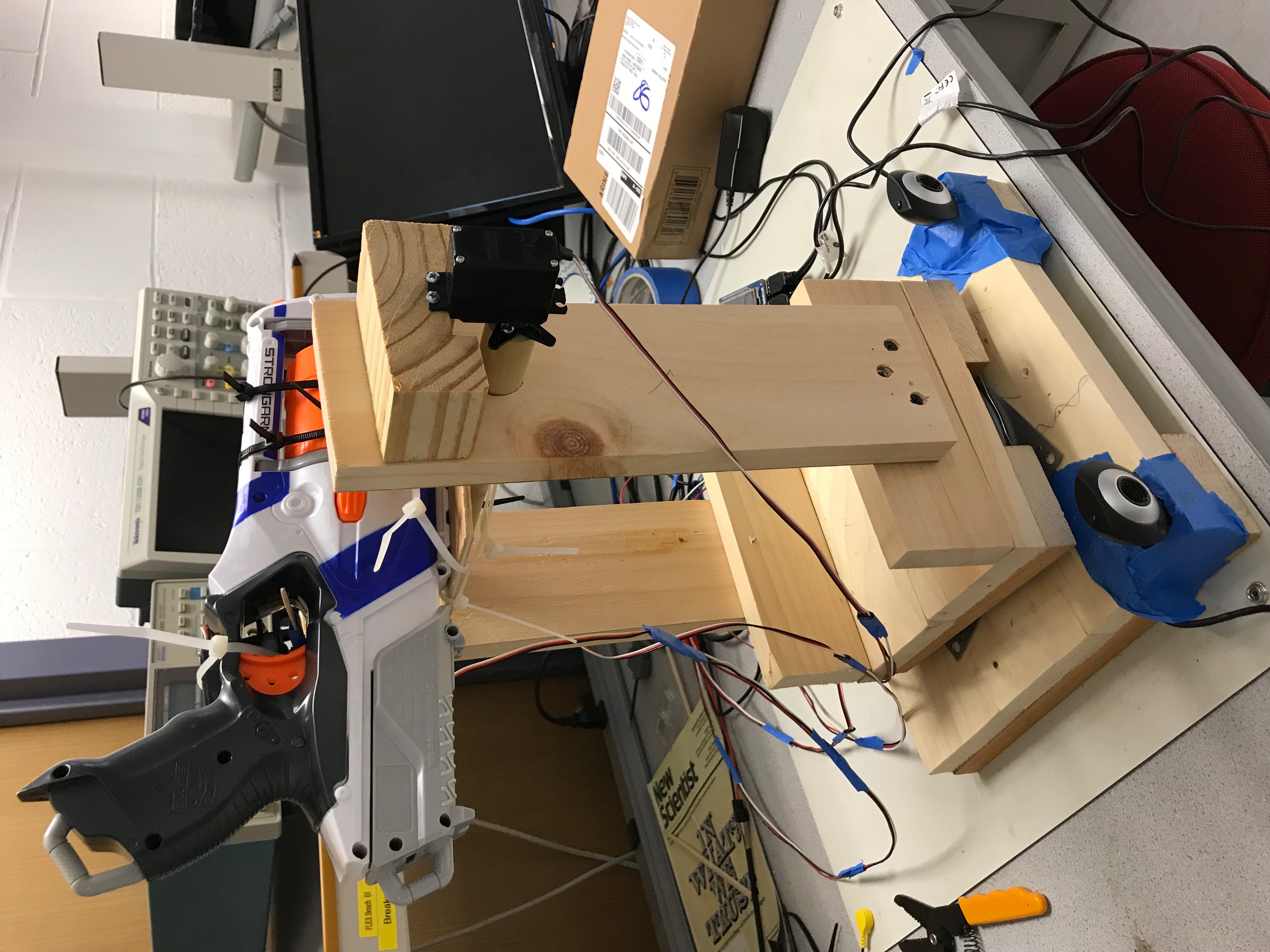
The aim of this project was to use stereo vision to measure the global position (x,y,z) of a target and use this information to orient a Nerf gun to fire and and hit this target. This is done by solving an inverse kinematics problem that solve for both the necessary pitch and yaw angles.Drawings
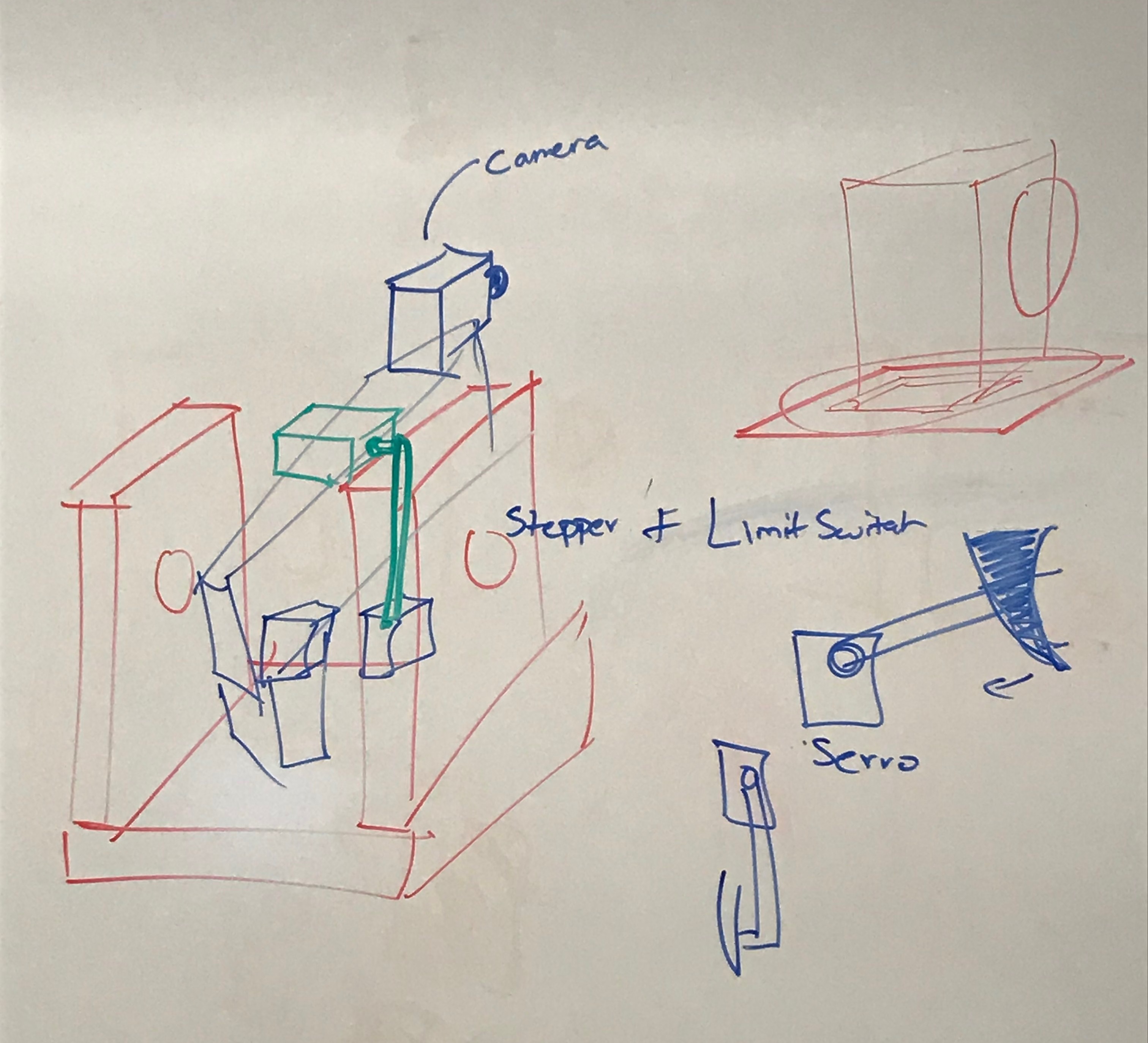
Preliminary board sketches of possible center actuator as well as support system for the Nerf targeting system.
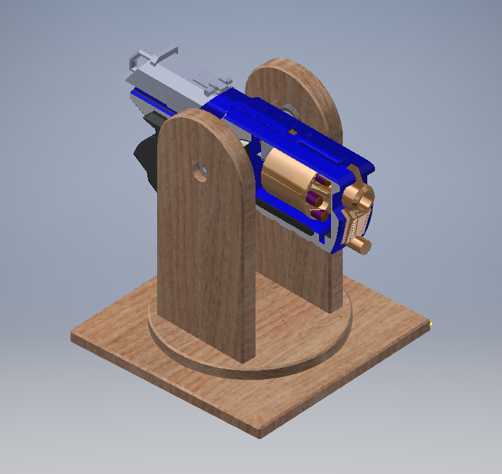
Initial CAD design of the targeting system.
Design
The design stage of the project was broken up into a mechatronics (mechanical and electrical) based component and a stereo vision (software) component. Both aspects were done simultaneously by each member of the group. The various deisng objectives were eventually merged together for motor control and PWM actuation.
Mechanical
The structure of the system was designed for facility of construction. The easier the design, the easier it would be for another person to replicate the work, which is one of the goals of the project. To do this, the dynamics of the system needed to be analyzed to better understand how to actuate the individual components. The dynamics could then be used to create a simplified robotic aparatus.
In order to design a system as described from the project objectives, the system would need to obtain the desired yaw angle and then the desired pitch angle. Since the direction of the projectile in the XY-plane is assumed to be invariant under external forces, the problem could be split apart into a problem in the global XY-plane and one in the local ZX-plane.
The base of the system was constructed with pieces of a 3''x4' piece of plywood. Three 9'' pieces were cut and placed together. Two thinner cut pieces (2''x9'') from a 2''x4' were used to join two pieces together with wood screws. A rectangular shaped hole was carved out from the middle of one of the pieces in order to make the hole for a servo to be mounted from above.
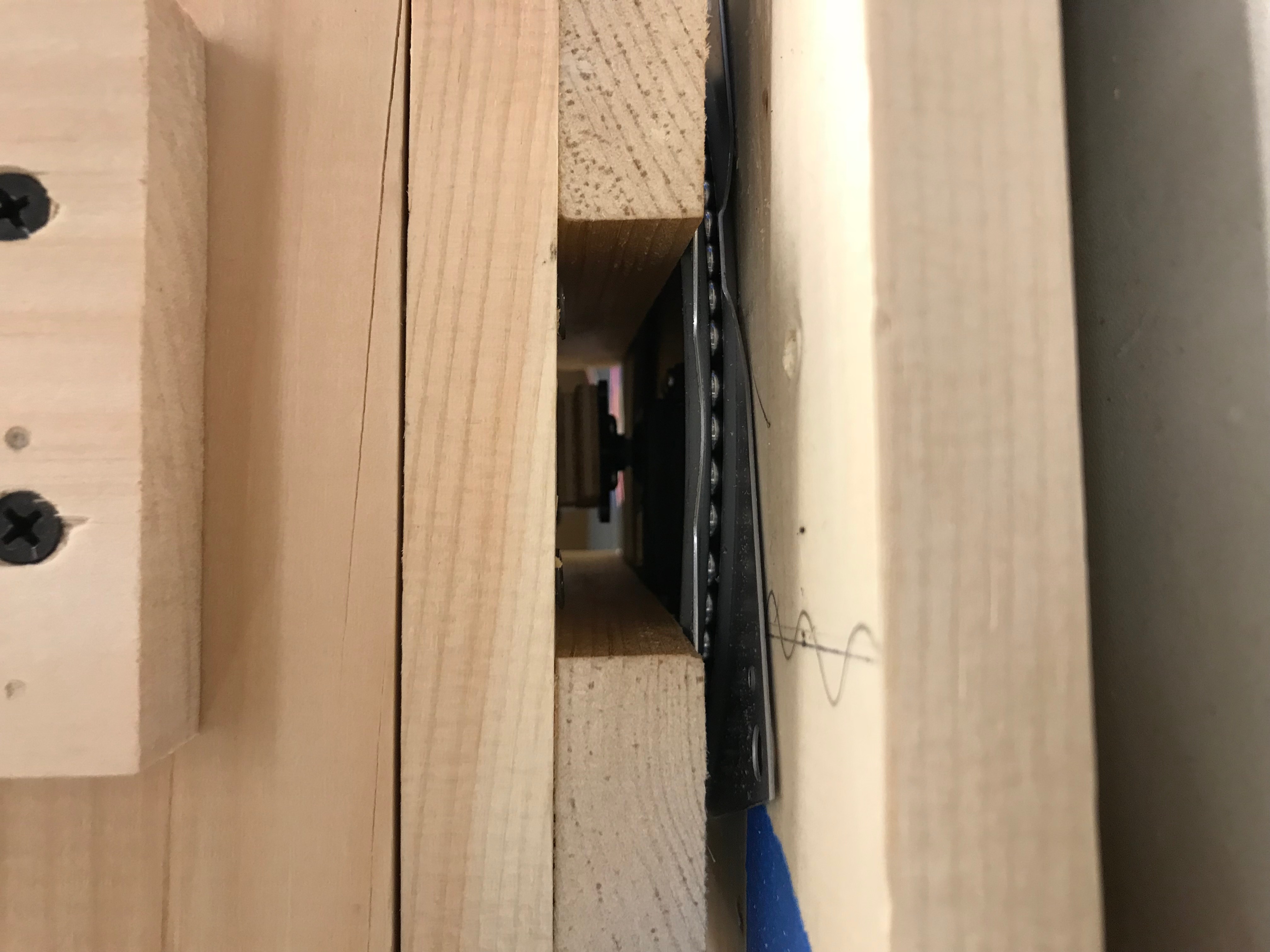
Bases attached by the standard servo for yaw
The upper part of the base was constructed with the same wood, but sized at two pieces of 3''x6'', stacked next to each other. These two pieces were also joined by two thinner cut pieces (2''x6'') and wood screws. At the center of the bottom of this base, a few very small pieces of wood (1''x1''x1/8'') were attached to a servo horn with wood screws. The attachment with the servo horn allowed this upper base to spin with the lower base solely due to servo input actuation. This input was the system's yaw control.
Two 3''x6'' uprights were attached to the upper rotating base as shown in the figure. The uprights allowed for a larger clearance for the Nerf gun. Two tall 3''x12'' pieces were attached to the sides of the uprights. These pieces were predrilled with 7/8'' diameter holes about 1.5'' from the top of each piece. This is where a dowel would be inserted for actuation about the pitch axis.
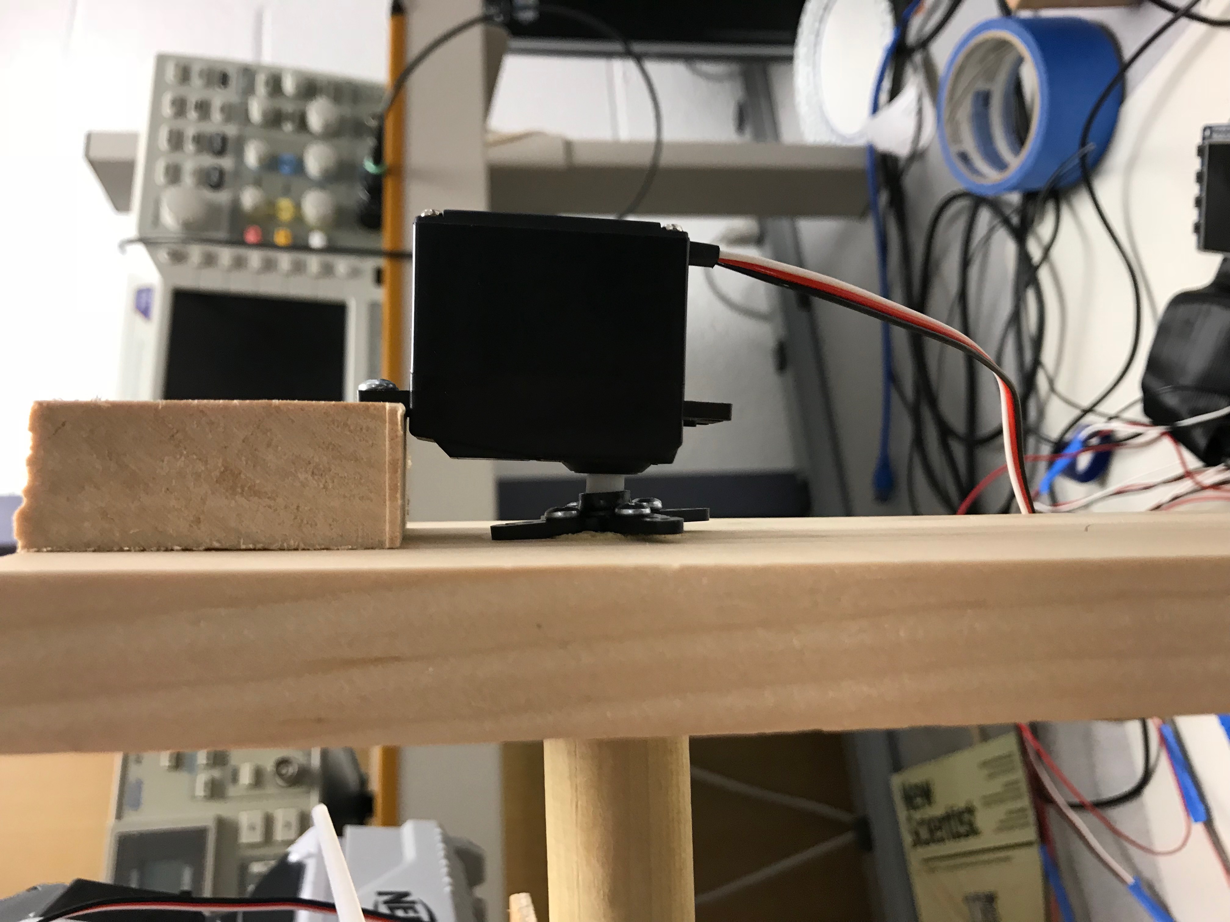
Dowels connected by the standard servo for pitch
The dowel itself was given a 3'' flat surface for mounting of a rectangular wooden piece. The wooden piece was itself mounted to the gun with wood screws. The Nerf gun was attached to the wooden plate on one of its flatter edges, and secured with zip-ties. This restricted the gun's motion to small perturbations in the plane of its mounting. At the end of each dowel, a servo horn was attached to allow two servos to actuate the system properly by providing enough torque.
A servo was ziptied to the handle of the Nerf gun so that the a servo horn (with a popsicle stick attached to one of its horns) would be able to push the trigger when the proper command was given.
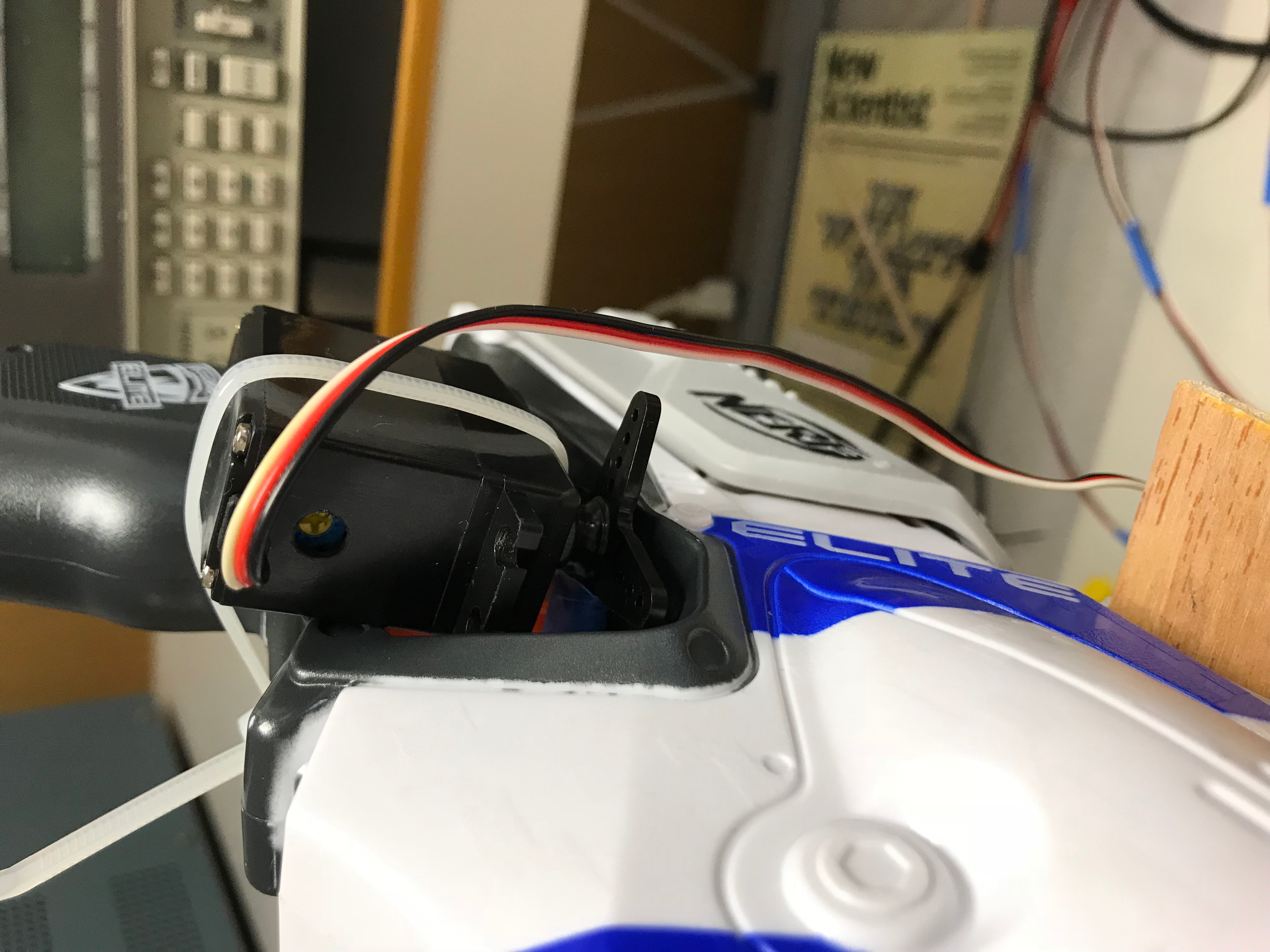
Continuous rotation servo connected to the handle for trigger actuation.
Electrical
The microcontroller used for this project was a standard Raspberry Pi 3. The Pi was connected to a TFT display for its modularity and extended operation, without any monitoring of computer vision software feedback. A breadboard was used to connect all motor inputs and outputs. On both '+' rails of the breadboard, an external power input of 5 V was run. The '-' rails subsequently were connected to the Pi's ground (GND). The 3V3 input was NOT used in the command of the motors, becuase this did not provide enough torque for the system to be actuated properly.
For each servomotor used, the power wire was connected to the external power rails, and connected to a common ground. The signal wire input depended on the motor used. For the yaw axis motor, a standard 180 degree servo was used. Two standard 180 degree servos were used for actuation of pitch, one located at each end of the dowel. One continuous rotation servo was used for the trigger mechanism. The continuous and standard servos both required different PWM signals as the ranges were somewhat different. A standard servo operates on a range of 0.75ms to 2.25ms while the continous servos operate from 1.3ms to 1.7ms.
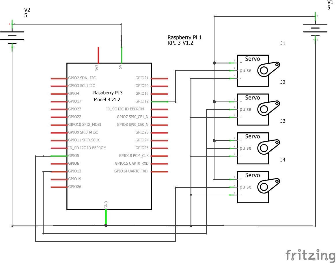
Electronic schematic for the system
In the schematic given above, J1 controls the yaw, J2 and J3 control the pitch, and J4 controls the trigger. V1 is the external voltage source to power the motors and V2 is the power provided to the Raspberry Pi from the outlet.
Hardware PWM was used for the actuation of the standard servos. This provided enough robustness for the system to be actuated to the proper command state without significant error in position.
This being said, no sensors were used for feedback control of the system. Since hardware PWM would provide enough robustness for the accuracy desired in the project, there was no need to create a feedback system to correct for position.
Software
Stereo Vision and Object Detection
To determine the targets global position, we made use of the opencv library to implement stereo vision. Stereo vision is a method of mimicking vision of human eyes by using two cameras to perceive three dimensions. This is accomplished by making use of similar triangles. As seen in the below figure, each camera has its own coordinate axis of which the horizontal position differs, but the perceived depth is the same.
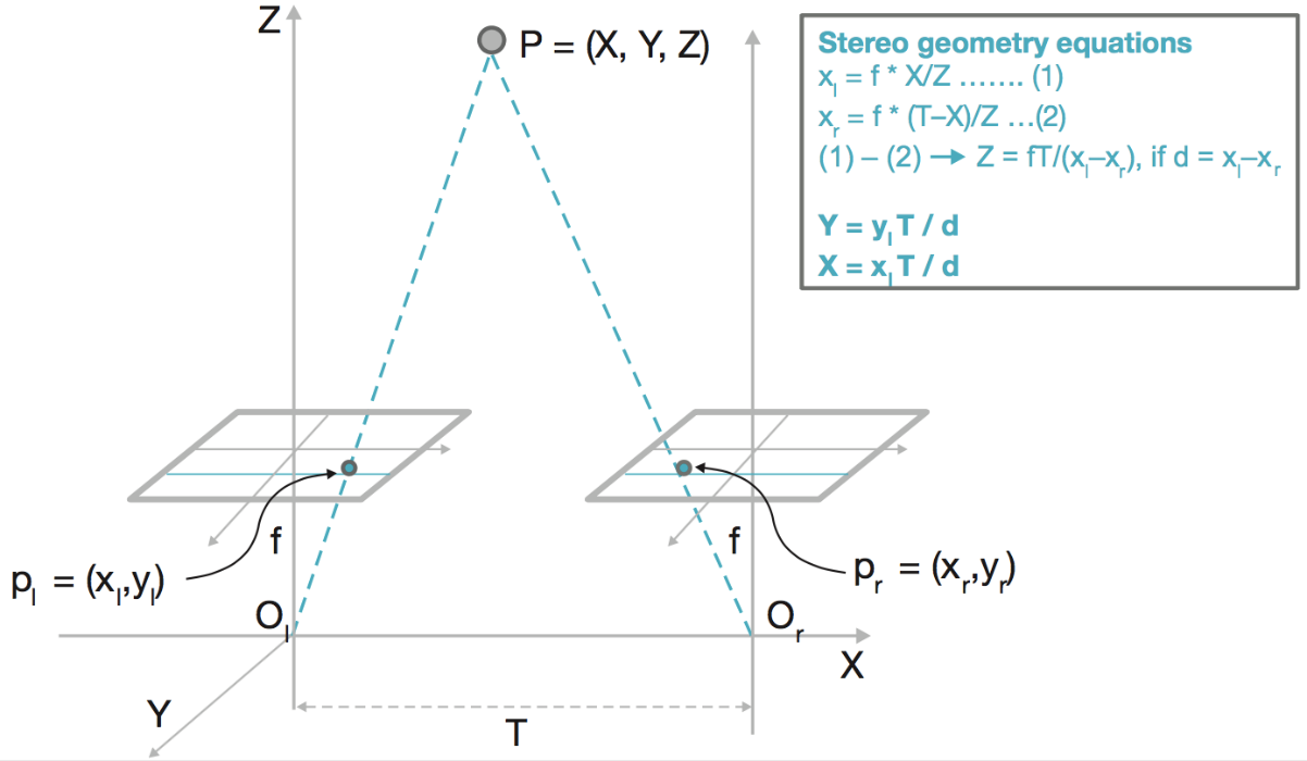
Stereo Vision Configuration
Depending on the depth of the point, the horizontal position of the same point in each cameras image plane will become closer in value the further away the point is. This relation, called the disparity map, is used to generate a mapping from the image coordinates to the corresponding depth value. The value of the disparity map is calculated by taking the difference of the left and right cameras horizontal position. The relation to get the depth from this disparity value is the following:
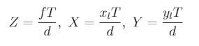
here f is the focal length of the camera in pixel units, T is the baseline distance (separation distance between the two cameras) in meters and d is the disparity also in pixel units.
To accomplish all of this, we first needed to calibrate the cameras to determine the focal length of each camera. This was done by using the calibrateCamera method from opencv for each camera. To use this method, we first need to have each camera take pictures of an object with known geometry. A chessboard is commonly used for calibration purposes, as such, we decided to use a 9x7 grid. The chessboard is found, and its coordinates saved using the findChessboardCorners method. Generally, the more pictures of a chessboard there are, the better the calibration which should lead to an undistorted image. However, we determined that anymore than 10-12 images per camera would result in a distorted calibration which would render the remaining calibrations useless. Thus, we performed the calibration with 8-10 images which allowed for the determination of the cameras intrinsic properties. These include the camera matrix which contains the focal lengths in the x and y directions as well as the center coordinates of each camera. Additionally, this method returns the distortion coefficients, the translation vector as well as the rotation vector for each camera. Using these vectors, we can now perform a stereo calibration on both cameras using the stereoCalibration method. This method returned the rotation and translation matrices between the two cameras as well as the essential and fundamental matrices. These are also known as the extrinsic properties of the stereo system.
The methods used in this calibration were all found in the opencv tutorial for calibrating a pair of cameras for stereo vision. However, the implementations that were shown were outdated which required for us to determine the knew implementation. This method can be shown in the code appendix under the name fullStereoCalibration. From these calibration parameters, we were able to perform a stereo rectification of the images from both cameras. What this does is take the image from each camera and project it onto the same image, essentially creating one image from both cameras. This was done by the stereoRectify method which returned a rotation rectification matrix for both cameras as well as projection matrices in this new rectified frame for these cameras. Additionally, this method returns a disparity-to-depth mapping matrix. With all these properties, we were able to generate a mapping for each camera using the initUndistortRectifyMap method. This allows for us to apply all the previous calibrations as well as image rectifications through a simple mapping. Thus, we can store these mappings and reuse them later. The last step of this stereo calibration was to generate the disparity map. Unfortunately, we were not able to generate a clear enough disparity map. Shown below is a sample output of our best tuned disparity settings. For this reason, we choose to move away from creating the disparity map.
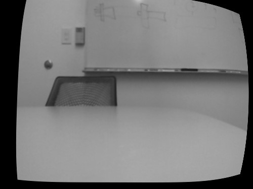
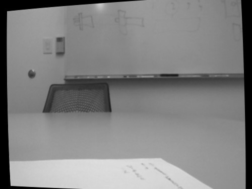
Example left and right image as a result of the Calibration Process
Resulting Diparity Map
To workaround the disparity map issue, we decided to perform object recognition first to determine the camera coordinates of the target. This would allow for us to manually calculate the disparity of the object to ultimately find the global coordinates. We first attempted to use a flannBasedMatcher to try and find similarities between an image of the target and an image containing the target. This method did not work as the matcher was not able to find more than 3 matches between the target image and the image fed into the classifier. For this reason, we decided to try and locate the target by detecting the circle on the target image. To do this, we defined a threshold that contained the color of the target, essentially reducing the number of objects that need to be classified. We tried a few different colors for the target such as red and blue. However, we ultimately decided to use a black target as it proved to have the best results.
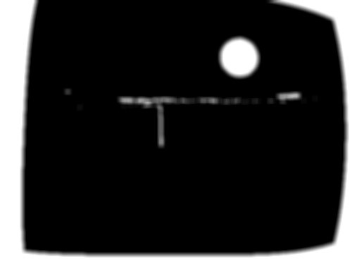
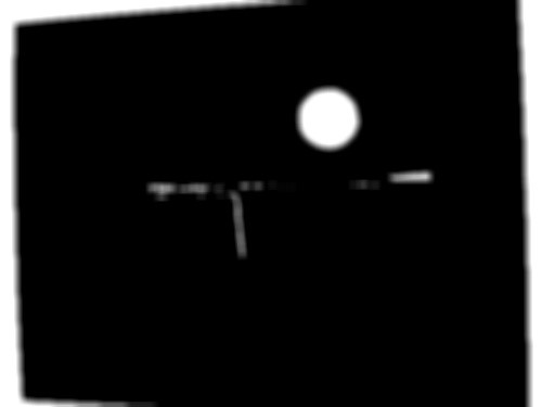
Result of Applying a Threshold on Images from the Cameras
From here we fed this image into the HoughCircles method that would detect the circle from this image. We chose to go this route because HoughCircles tended to classify non-circular objects as circles. We were able to increase the number of data points it needed to consider an object a circle, but this also made it harder to classify our target.
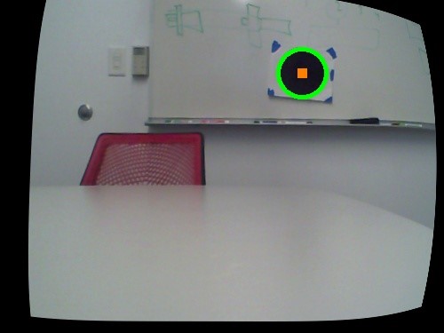
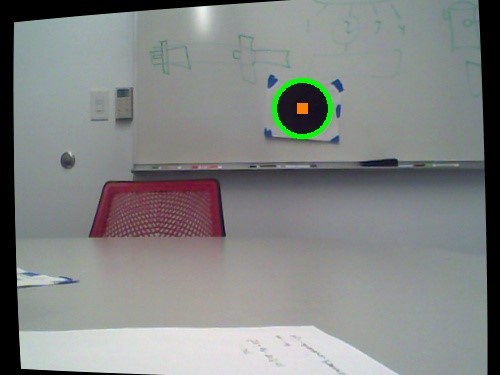
The Located Target Displayed on the Camera Image
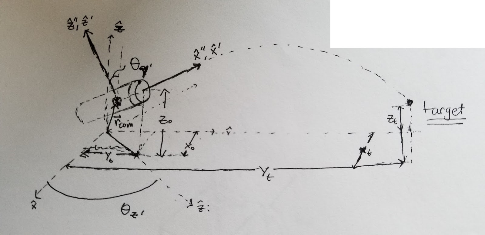
Inverse Kinematics
The inverse kinematics model was first created in MATLAB. The yaw angle was simple to solve since all that was needed was the target x and y positions. The pitch angle however was a lot more complicated. Since the pitch would vary the initial height of the release point for the nerf gun bullet, the initial conditions were also a function of pitch. Our solution to this was to assume that the initial position was fixed (i.e. not a function of the pitch) and solve for an initial value of the pitch. We would then use this value again to update this pitch value. We found that this second iteration was all that was needed to obtain a reasonable value for the pitch (error less than 10^-4).
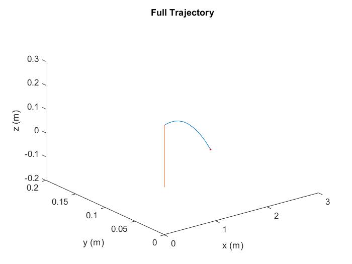
Nerg Gun Simulator Output to Target Position of (2.8300,0.1679,-0.1990)
Testing
Software
To test the accuracy of the calculated depth values, we placed the target at a known distance away from the cameras and compared the output to the true value. In general, the resulting depth was somewhat accurate, but more so precise. The values that we got were at most off by about 0.2-0.4m. We did not see if this was the same result in the global x and y directions but we assumed that this error would likely be of equal or lower value.
The servos, especially the continuous servo, had to be calibrated such that the duty cycles that were listed on the data sheets were true representations of the servos behavior. To do this, we set a duty cycle that normally should result in little to no motion of the continuous servo. We then tuned the trimpot that was attached to the motor untill the servo reached approximately zero motion. This was used to trigger the nerf gun. Additionally, we needed to determine the exact zero position of the standard servos so that this orientation could match up to our defined zero angle orientation.
Mechatronics
After the angle calibrations were performed from the software, we needed to check if these angles were still correct with the added load of the system. To test the electromechanical assembly, the system was first calibrated at its optimal 0 degree angle for yaw and pitch. We determined that the commanded angles were not offset by much due to the added load (approximately 3 degrees in yaw). We decided to offset the angle inputs to essentially define a new software based zero point.
Result
For the most part, we were able to achieve all of our objectives, however, there were a few things that we would have liked to imporve on our system. For one, the cameras we were using were not the best quality which resulted in poor performance on the Pi. If we had been able to use cameras with a higher resolution, we likely could have increased the maximum perceivable depth of our system ultimately increasing the range of the nerf gun. Additionally, if our budget had been higher, we would have definitely invested in a semi-automatic/automatic nerf gun which would have made triggering the nerf gun much simipler. On top of this, the mechanical design of the mount for the nerf gun could have been optimized to alleviate the need for zipties as well as smoothened out the motion of the pitch axis. All in all, we do believe the project was successful as we were able to hit over 50% of our targets given all of the above constraints.
Future Work
In the future, we believe that this project could be extended to incorporate moving targets. If one were able to optimize the code such that a higher frame rate were achievable, a velocity could be estimated for a target. Additionally, this project could also incorporate a user interface allowing for the user to specify targets as well as autonomously locating targets on the fly.
Work Distribution
Jonah Okike-Hephzibah
jo356@cornell.edu
Implemented Stereo Vision, object detection, designed the inverse kinematics algorithm, developed motor control commands, synthesized software for execution of full system.
Anshuman Das
ad765@cornell.edu
Designed full mechanical system, partly worked on hardware motor control.
Parts List
- Raspberry Pi (Provided By Lab) - 1: $35.00
- Web Cameras (Provided By Lab) - 2: $5.00
- Lazy Suzan Turntable Bearing - 1: $5.00
- Nerf Gun - 1: $12.99
- Standard Servos (Provided By Lab) - 3: $10.00
- Continuous Servo (Provided By Lab) - 1: $10.00
Total: $102.99
References
OpenCVPigpio Library
R-Pi GPIO Document
Full Stereo Calibration Reference Code
Stereo Vision Configuration Image
Code Appendix
Full Stereo Calibration
# fullStereoCalibration.py
# Camera Calibration For Stereo Vision
import cv
import cv2
import sys
import numpy as np
import filtering

keep_processing = True
camera_to_use = 0 # left camera will be 0, right will be 1

#############################

# Kernel size:
sz = 3

# Desired x pixel value:
rat = 500.0

# Output file to save mapping:
outputFile = 'DepthMapping'

# STAGE 1:

# define video capture object
camL = cv2.VideoCapture()
camR = cv2.VideoCapture()

# Define display window names:

windowNameL = "LEFT Camera Input"
windowNameR = "RIGHT Camera Input"

print( "s : swap cameras left and right" )
print( "c : continue to next state" )

if ((camL.open(camera_to_use)) and (camR.open(camera_to_use + 1))):

    while (keep_processing):

        # grab frames from camera (this ensures best time sync.):
        camL.grab()
        camR.grab()

        # retrieve images in slow(er) time

        ret, frameL = camL.retrieve()
        ret, frameR = camR.retrieve()
        #ret, frameL = camL.read()
        #ret, frameR = camR.read()

        # Display image
        cv2.imshow(windowNameL, frameL)
        cv2.imshow(windowNameR, frameR)

        key = cv2.waitKey(300) & 0xFF # wait 40 ms

        if (key==ord('c')):
            keep_processing = False
        elif (key == ord('s')):
            # swap the cameras if specified
            tmp = camL
            camL = camR
            camR = tmp
else:
    print("Cannot open pair of cameras connected.")
    sys.exit()

#########################################################

do_calibration = False
termination_criteria_subpix = (cv2.TERM_CRITERIA_EPS + cv2.TERM_CRITERIA_MAX_ITER, 1000, 0.00001)

# Define checkerboard size:
patternX = 9 #7
patternY = 7 #9
square_size_in_mm = 1 #23 #0.040 # actually in meters

# prepare object points, like (0,0,0), (1,0,0), (2,0,0) ...,(6,5,0)
objp = np.zeros((patternX*patternY,3), np.float32)
objp[:,:2] = np.mgrid[0:patternX,0:patternY].T.reshape(-1,2)*square_size_in_mm

# create arrays to store object points and image points from all the images.
objpoints = [] #3d point in real world space
imgpointsR = [] # 2d points in right image plane.
imgpointsL = [] # 2d points in left image plane

# count number of chessboard detection (across both images)
chessboard_pattern_detections = 0

print()
print("--> hold up the chessboard")

while( not(do_calibration)):

    # grab frames from camera (to ensure best time sync)
    camL.grab()
    camR.grab()

    # retrieve images in slow(er) time

    retL, frameL = camL.retrieve()
    retR, frameR = camR.retrieve()

    r = rat/ frameL.shape[1]
    dim = (int(rat), int(frameL.shape[0]*r))

    frameL = cv2.resize(frameL, dim, interpolation = cv2.INTER_AREA)
    frameR = cv2.resize(frameR, dim, interpolation = cv2.INTER_AREA)

    frameL = filtering.flt(frameL,sz)
    frameR = filtering.flt(frameR,sz)

    # convert to grayscale
    grayL = cv2.cvtColor(frameL,cv2.COLOR_BGR2GRAY)
    grayR = cv2.cvtColor(frameR,cv2.COLOR_BGR2GRAY)

    # Find the chess board corners in the image
    retL, cornersL = cv2.findChessboardCorners(grayL, (patternX,patternY),None, cv2.CALIB_CB_ADAPTIVE_THRESH | cv2.CALIB_CB_FAST_CHECK | cv2.CALIB_CB_NORMALIZE_IMAGE)
    retR, cornersR = cv2.findChessboardCorners(grayR, (patternX,patternY),None, cv2.CALIB_CB_ADAPTIVE_THRESH | cv2.CALIB_CB_FAST_CHECK | cv2.CALIB_CB_NORMALIZE_IMAGE)

    # If found, add object points, image points (after refining them)

    if ((retR == True) and (retL == True)):

        chessboard_pattern_detections += 1

        # add object points to global list
        objpoints.append(objp)

        # refine corner locations to sub-pixel accuracy
        corners_sp_L = cornersL
        cv2.cornerSubPix(grayL,corners_sp_L,(11,11),(-1,-1),termination_criteria_subpix)
        imgpointsL.append(corners_sp_L)

        corners_sp_R = cornersR
        cv2.cornerSubPix(grayR,corners_sp_R,(11,11),(-1,-1),termination_criteria_subpix)
        imgpointsR.append(corners_sp_R)

        # Draw and display the corners
        drawboardL = frameL
        cv2.drawChessboardCorners(drawboardL,(patternX,patternY), corners_sp_L, retL)
        drawboardR = frameR
        cv2.drawChessboardCorners(drawboardR,(patternX,patternY), corners_sp_R, retR)

        text = 'detected: ' + str(chessboard_pattern_detections)
        cv2.putText(drawboardL,text,(10,25),cv2.FONT_HERSHEY_SIMPLEX,1,(0,255,0),2,8)

        cv2.imshow(windowNameL,drawboardL)
        cv2.imshow(windowNameR,drawboardR)
    else:

        text = 'detected: ' + str(chessboard_pattern_detections)
        cv2.putText(frameL, text, (10,25), cv2.FONT_HERSHEY_SIMPLEX,1,(0,255,0),2,8)

        cv2.imshow(windowNameL,frameL)
        cv2.imshow(windowNameR,frameR)

    key = cv2.waitKey(600) & 0xFF # wait 100ms
    if (key ==ord('c')):
        do_calibration = True

print( "Starting - calibration...")

ret, mtxL, distL, rvecsL, tvecsL = cv2.calibrateCamera(objpoints, imgpointsL, grayL.shape[::-1])
ret, mtxR, distR, rvecsR, tvecsR = cv2.calibrateCamera(objpoints, imgpointsR, grayR.shape[::-1])

print( "Finished - calibration.")
print( "Left matrix: \n" + str(mtxL) + "...\n")
print( "Right matrix: \n" + str(mtxR) + "...\n" )

# perform undistortion of the images

keep_processing = True

print()
print("--> performing undistortion")

while(keep_processing):

    # grab frames from camera
    camL.grab()
    camR.grab()

    # retrieve image
    ret, frameL = camL.retrieve()
    ret, frameR = camR.retrieve()

    r = rat/ frameL.shape[1]
    dim = (int(rat), int(frameL.shape[0]*r))

    frameL = cv2.resize(frameL, dim, interpolation = cv2.INTER_AREA)
    frameR = cv2.resize(frameR, dim, interpolation = cv2.INTER_AREA)

    frameL = filtering.flt(frameL,sz)
    frameR = filtering.flt(frameR,sz)

    undistortedL = cv2.undistort(frameL, mtxL, distL) #, None, None)
    undistortedR = cv2.undistort(frameR, mtxR, distR) #, None, None)

    # display image

    cv2.imshow(windowNameL, undistortedL)
    cv2.imshow(windowNameR, undistortedR)

    key = cv2.waitKey(40) & 0xFF # wait 40 ms

    if (key == ord('c')):
        keep_processing = False

# show mean re-projection error of the object points onto the image(s)

tot_errorL = 0
tot_errorR = 0
for i in range(len(objpoints)):
    imgpointsL2, _ = cv2.projectPoints(objpoints[i], rvecsL[i], tvecsL[i], mtxL, distL)
    imgpointsR2, _ = cv2.projectPoints(objpoints[i], rvecsR[i], tvecsR[i], mtxR, distR)
    errorL = cv2.norm(imgpointsL[i], imgpointsL2, cv2.NORM_L2)/len(imgpointsL2)
    errorR = cv2.norm(imgpointsR[i], imgpointsR2, cv2.NORM_L2)/len(imgpointsR2)
    tot_errorL += errorL
    tot_errorR += errorR

print( "LEFT: Re-projection error: ", tot_errorL/len(objpoints))
print( "RIGHT: Re-projection error: ", tot_errorR/len(objpoints))

####################3######################

termination_criteria_extrinsics = (cv2.TERM_CRITERIA_EPS + cv2.TERM_CRITERIA_MAX_ITER, 30, 0.001) # 2nd item was 100

print()
print("Start - extrinsic calibration...")

camera_matrix_l = np.zeros(mtxL.shape)
camera_matrix_r = np.zeros(mtxR.shape)
dist_coeffs_l = np.zeros(distL.shape)
dist_coeffs_r = np.zeros(distR.shape)
R = np.zeros(mtxL.shape)
T = np.zeros((3,1)) # len(tvecsL)
E = np.zeros(mtxL.shape)
F = np.zeros(mtxL.shape)
(rms_stereo, camera_matrix_l, dist_coeffs_l, camera_matrix_r, dist_coeffs_r, R, T, E, F) = \
             cv2.stereoCalibrate(objpoints, imgpointsL, imgpointsR, grayL.shape[::-1], mtxL, distL, mtxR, distR, R,T,E,F, criteria=termination_criteria_extrinsics)

#cv2.stereoCalibrate(objpoints, imgpointsL, imgpointsR, grayL.shape[::-1], camera_matrix_l, dist_coeffs_l, camera_matrix_r, dist_coeffs_r,R,T,E,F, criteria=termination_criteria_extrinsics, flags=0)
print("Extrinsic calibration complted." )
#print( "STEREO: RMS left ot right re-projection error: ", rms_stereo)
print("Fundamental Matrix: \n" + str(F))
print( "Old cameraMatrixR: \n" + str(mtxR))
print( "New cameraMatrixR: \n" + str(camera_matrix_r))
print( "STEREO: RMS left to right re-projection error: ", rms_stereo)

#################################################

RL = np.zeros((3,3))
RR = np.zeros((3,3))
PL = np.zeros((3,4))
PR = np.zeros((3,4))
Q = np.zeros((4,4))

cv.StereoRectify(cv.fromarray(camera_matrix_l),cv.fromarray(camera_matrix_r), cv.fromarray(dist_coeffs_l), cv.fromarray(dist_coeffs_r), grayL.shape[::-1], \
                 cv.fromarray(R), cv.fromarray(T), cv.fromarray(RL), cv.fromarray(RR), cv.fromarray(PL), cv.fromarray(PR), cv.fromarray(Q),flags = 0,alpha=-1) #flags = cv.CV_CALIB_ZERO_DISPARITY

# optional flag for stereoRectify: flags=cv.CV_CALIB_ZERO_DISPARITY
#cv2.stereoRectify(camera_matrix_l, camera_matrix_r, dist_coeffs_l, dist_coeffs_r, grayL.shape[::-1], R, T, RL, RR, PL, PR, Q, flags=cv.CV_CALIB_ZERO_DISPARITY, alpha=-1)

print( 'Rl = \n' + str(RL) )
print( 'Rr = \n' + str(RR) )
print( 'Pl = \n' + str(PL) )
print( 'Pr = \n' + str(PR) )
print( 'T = \n' + str(T) )
print( 'Q = \n' + str(Q) )

mapL1, mapL2 = cv2.initUndistortRectifyMap(camera_matrix_l, dist_coeffs_l, RL, PL, grayL.shape[::-1], cv2.CV_32FC1)
mapR1, mapR2 = cv2.initUndistortRectifyMap(camera_matrix_r, dist_coeffs_r, RR, PR, grayL.shape[::-1], cv2.CV_32FC1)

np.savez_compressed(outputFile, imageSize=grayL.shape[::-1], mapL1 = mapL1, mapL2 = mapL2, mapR1 = mapR1, mapR2 = mapR2, PL=PL, PR=PR)

print()
print("-> performing rectification")

keep_processing = True

while (keep_processing):

    camL.grab()
    camR.grab()

    ret, frameL = camL.retrieve()
    ret, frameR = camR.retrieve()

    r = rat/ frameL.shape[1]
    dim = (int(rat), int(frameL.shape[0]*r))

    frameL = cv2.resize(frameL, dim, interpolation = cv2.INTER_AREA)
    frameR = cv2.resize(frameR, dim, interpolation = cv2.INTER_AREA)

    frameL = filtering.flt(frameL,sz)
    frameR = filtering.flt(frameR,sz)

    undistorted_rectifiedL = cv2.remap(frameL, mapL1, mapL2, cv2.INTER_LINEAR)
    undistorted_rectifiedR = cv2.remap(frameR, mapR1, mapR2, cv2.INTER_LINEAR) #cv2.CV_WARP_FILL_OUTLIERScv2.INTER_LINEAR)

    cv2.imshow(windowNameL, undistorted_rectifiedL)
    cv2.imshow(windowNameR, undistorted_rectifiedR)

    key = cv2.waitKey(40) & 0xFF

    if (key == ord('c')):
        keep_processing = False

print()
print("-> calc. disparity image")

max_disparity = 128
window_size = 3

keep_processing = True
windowNameD = "SGBM Stereo Disparity - Output"

while (keep_processing):

    camL.grab()
    camR.grab()

    ret, frameL = camL.retrieve()
    ret, frameR = camR.retrieve()

    r = rat/ frameL.shape[1]
    dim = (int(rat), int(frameL.shape[0]*r))

    frameL = cv2.resize(frameL, dim, interpolation = cv2.INTER_AREA)
    frameR = cv2.resize(frameR, dim, interpolation = cv2.INTER_AREA)

    frameL = filtering.flt(frameL,sz)
    frameR = filtering.flt(frameR,sz)

    grayL = cv2.cvtColor(frameL,cv2.COLOR_BGR2GRAY)
    grayR = cv2.cvtColor(frameR,cv2.COLOR_BGR2GRAY)

    undistorted_rectifiedL = cv2.remap(grayL, mapL1, mapL2, cv2.INTER_LINEAR)
    undistorted_rectifiedR = cv2.remap(grayR, mapR1, mapR2, cv2.INTER_LINEAR)

    stereoProcessor = cv2.StereoSGBM(0,128,window_size,8*3*window_size**2, 32*3*window_size**2,1,0,10,100,32, False)
    disparity = stereoProcessor.compute(undistorted_rectifiedL, undistorted_rectifiedR)
    cv2.filterSpeckles(disparity,0,4000, 128)

    disparity_scaled = (disparity/ 16.).astype(np.uint8) + abs(disparity.min())

    # display image

    cv2.imshow(windowNameL,undistorted_rectifiedL)
    cv2.imshow(windowNameR,undistorted_rectifiedR)

    # display disparity

    indx = indx+1

    cv2.imshow(windowNameD, disparity_scaled)

    key = cv2.waitKey(40) & 0xFF

    if (key == ord('c')):
        keep_processing = False

cv2.destroyAllWindows()
Depth Output
# depthOutput.py
# Get Depth of Circles:

import cv2
import numpy as np

T = 0.24 # baseline in meters

# Desired x pixel value:
rat = 500.0

# Load mapping
calibration = np.load('DepthMapping.npz', allow_pickle=False)
imgSize = tuple(calibration["imageSize"])
mapL1 = calibration["mapL1"]
mapL2 = calibration["mapL2"]
mapR1 = calibration["mapR1"]
mapR2 = calibration["mapR2"]
PL = calibration["PL"]
PR = calibration["PR"]

windowNameL = "LEFT Camera Input"
windowNameR = "RIGHT Camera Input"
windowNameD = "Disparity Map"

print( "s : swap cameras left and right" )
print( "c : continue to next state" )

camera_to_use = 0
keep_processing = True
waitTime = 340
camL = cv2.VideoCapture(camera_to_use)
camR = cv2.VideoCapture(camera_to_use+1)

if ((camL.open(camera_to_use)) and (camR.open(camera_to_use + 1))):

    while (keep_processing):

        # grab frames from camera (this ensures best time sync.):
        camL.grab()
        camR.grab()

        # retrieve images in slow(er) time

        ret, frameL = camL.retrieve()
        ret, frameR = camR.retrieve()

        # Display image
        cv2.imshow(windowNameL, frameL)
        cv2.imshow(windowNameR, frameR)

        key = cv2.waitKey(waitTime) & 0xFF # wait 40

        if (key==ord('c')):
            keep_processing = False
        elif (key == ord('s')):
            # swap the cameras if specified
            tmp = camL
            camL = camR
            camR = tmp
else:
    print("Cannot open pair of cameras connected.")
    sys.exit()

keep_processing = True

circlesL = {} #np.array({})
circlesR = {} # np.array({})

min_black = np.array([0,0,0]) #np.array([0,50,100]) #np.array([0,100,80]) #np.array([0,0,0])
max_black = np.array([180,255,50]) #np.array([10,256,256]) #np.array([180,255,60])

min_black2 = np.array([0,0,50]) #np.array([170,50,100]) #np.array([80,0,0])
max_black2 = np.array([180,255,100]) #np.array([180, 256,256]) #np.array([255,255,60])

param1 = 90.0
minRad = 0

kernel = cv2.getStructuringElement(cv2.MORPH_ELLIPSE, (15,15))

fnd = 0

while (keep_processing):

    camL.grab()
    camR.grab()

    ret, frameL = camL.retrieve()
    ret, frameR = camR.retrieve()

    r = rat/ frameL.shape[1]
    dim = (int(rat), int(frameL.shape[0]*r))

    frameL = cv2.resize(frameL, dim, interpolation = cv2.INTER_AREA)
    frameR = cv2.resize(frameR, dim, interpolation = cv2.INTER_AREA)

    undistorted_rectifiedL = cv2.remap(frameL, mapL1, mapL2, cv2.INTER_LINEAR)
    undistorted_rectifiedR = cv2.remap(frameR, mapR1, mapR2, cv2.INTER_LINEAR)

    image_blurL = cv2.medianBlur( undistorted_rectifiedL, 3)
    image_blurR = cv2.medianBlur( undistorted_rectifiedR, 3)

    hsvL = cv2.cvtColor(image_blurL, cv2.COLOR_BGR2HSV)
    hsvR = cv2.cvtColor(image_blurR, cv2.COLOR_BGR2HSV)

    maskL = cv2.inRange(hsvL, min_black, max_black)
    min_black = np.array([0,0,0])
    max_black = np.array([180,255,60])
    maskR = cv2.inRange(hsvR, min_black, max_black)

    # filter by brightness
    maskL2 = cv2.inRange(hsvL, min_black2, max_black2)
    min_black2 = np.array([80,0,0])
    max_black2 = np.array([255,255,60])
    maskR2 = cv2.inRange(hsvR, min_black2, max_black2)

    imgL = cv2.addWeighted(maskL, 1.0, maskL2, 1.0, 0)
    imgR = cv2.addWeighted(maskR, 1.0, maskR2, 1.0, 0)

    imgL = cv2.GaussianBlur( imgL, (9,9), 5, 5)
    imgR = cv2.GaussianBlur( imgR, (9,9), 5, 5)

    cv2.imshow( "red Hue Left", imgL)
    cv2.imshow( "red Hue Right", imgR )

    if fnd == 3:
        cv2.imwrite('hueResL.jpg',imgL)
        cv2.imwrite('hueResR.jpg',imgR)

    w,_ = imgL.shape

    circlesL = cv2.HoughCircles(imgL, cv2.cv.CV_HOUGH_GRADIENT, 1, w/8, param2 = param1/2, minRadius = minRad ) #20, param1, param1, minRad )
    circlesR = cv2.HoughCircles(imgR, cv2.cv.CV_HOUGH_GRADIENT, 1, w/8, param2 = param1/2, minRadius = minRad ) #20, param1, param1, minRad )

    # ensure at least some circles were found
    if ((circlesL is not None) and (circlesR is not None)):
        # convert the (x,y) coordinates and radius of the circles to integers
        circlesL = np.round(circlesL[0, :]).astype("int")
        circlesR = np.round(circlesR[0, :]).astype("int")

        numOfCircles, _ = circlesL.shape

        if (numOfCircles >= 1):
            for (x,y,r) in circlesL:

                # draw the circle in the output image, then draw a rectangle
                # corresponding to the center of the circle
                cv2.circle(undistorted_rectifiedL, (x,y), r, (0,255,0), 4)
                cv2.rectangle( undistorted_rectifiedL, (x- 5, y-5), (x+5, y+5), (0,128,255), -1)

            for (x,y,r) in circlesR:

                cv2.circle(undistorted_rectifiedR, (x,y), r, (0,255,0), 4)
                cv2.rectangle(undistorted_rectifiedR, (x-5, y-5), (x+5, y+5), (0,128,255), -1)


            l = np.array([[circlesL[0][0]],[circlesL[0][1]]], dtype=np.float)
            r = np.array([[circlesR[0][1]],[circlesR[0][1]]], dtype=np.float)

            pts = cv2.triangulatePoints(PL,PR,l,r)

            pts = pts * 2.3/7716.5

            pts = pts/pts[3,0]

            f = PL[0][0]
            sx = np.sign(circlesL[0][0]-PL[0][2]-circlesR[0][0]+ PR[0][2])*-1
            sy = np.sign(circlesL[0][1]-PL[1][2])
            disp = ((circlesL[0][0]-PL[0][2]-circlesR[0][0]+ PR[0][2])**2)**0.5
            Z = f * T/disp
            X = sx * Z * (circlesL[0][0]-PL[0][2])/f
            Y = sy * Z * (circlesL[0][1]-PL[1][2])/f

            print( "(x,y,z) = " + str((X,Y,Z)) )
            fnd = fnd + 1

    # display image
    cv2.imshow(windowNameL,undistorted_rectifiedL)
    cv2.imshow(windowNameR,undistorted_rectifiedR)

    if fnd == 3:
        cv2.imwrite('targetFoundL.jpg',undistorted_rectifiedL)
        cv2.imwrite('targetFoundR.jpg',undistorted_rectifiedR)

    key = cv2.waitKey(waitTime+60) & 0xFF

    if (key == ord('q')):
        keep_processing = False

cv2.destroyAllWindows()
Angle Operations
# angleOps.py
import numpy as np
import cv2

# Desired x pixel value:
rat = 500.0

T = 0.24 # baseline in meters

waitTime = 340

windowNameL = "LEFT Camera Input"
windowNameR = "RIGHT Camera Input"

def switchCameras(camL, camR,camera_to_use):

	waitTime = 340
	keep_processing = True

	print( "s : swap cameras left and right" )
        print( "c : continue to next state" )

	if ((camL.open(camera_to_use)) and (camR.open(camera_to_use + 1))):

	    while (keep_processing):

	        # grab frames from camera (this ensures best time sync.):
	        camL.grab()
	        camR.grab()

	        # retrieve images in slow(er) time

	        ret, frameL = camL.retrieve()
	        ret, frameR = camR.retrieve()

	        # Display image
	        cv2.imshow(windowNameL, frameL)
	        cv2.imshow(windowNameR, frameR)

	        key = cv2.waitKey(waitTime) & 0xFF # wait 40

	        if (key==ord('c')):
	            keep_processing = False
	        elif (key == ord('s')):
	            # swap the cameras if specified
	            tmp = camL
	            camL = camR
	            camR = tmp
	else:
	    print("Cannot open pair of cameras connected.")
	    sys.exit()

	cv2.destroyAllWindows()

	return (camL, camR)

def getDepth(camL,camR,mapL1,mapL2,mapR1,mapR2,PL,PR):

	targ = []

	keep_processing = True

	circlesL = {}
	circlesR = {}

	min_black = np.array([0,0,0])
	max_black = np.array([180,255,60])

	min_black2 = np.array([80,0,0])
	max_black2 = np.array([255,255,60])

	param1 = 90.0
	minRad = 0

	while (keep_processing and len(targ) <= 3):

	    camL.grab()
	    camR.grab()

	    ret, frameL = camL.retrieve()
	    ret, frameR = camR.retrieve()

	    r = rat/ frameL.shape[1]
	    dim = (int(rat), int(frameL.shape[0]*r))

	    frameL = cv2.resize(frameL, dim, interpolation = cv2.INTER_AREA)
	    frameR = cv2.resize(frameR, dim, interpolation = cv2.INTER_AREA)

	    undistorted_rectifiedL = cv2.remap(frameL, mapL1, mapL2, cv2.INTER_LINEAR)
	    undistorted_rectifiedR = cv2.remap(frameR, mapR1, mapR2, cv2.INTER_LINEAR)

	    image_blurL = cv2.medianBlur( undistorted_rectifiedL, 3)
	    image_blurR = cv2.medianBlur( undistorted_rectifiedR, 3)

	    hsvL = cv2.cvtColor(image_blurL, cv2.COLOR_BGR2HSV)
	    hsvR = cv2.cvtColor(image_blurR, cv2.COLOR_BGR2HSV)

	    # filter by color
	    maskL = cv2.inRange(hsvL, min_black, max_black)
	    min_black = np.array([0,0,0])
            max_black = np.array([180,255,60])
	    maskR = cv2.inRange(hsvR, min_black, max_black)

	    # filter by brightness
	    maskL2 = cv2.inRange(hsvL, min_black2, max_black2)
	    min_black2 = np.array([80,0,0])
            max_black2 = np.array([255,255,60])
	    maskR2 = cv2.inRange(hsvR, min_black2, max_black2)

	    imgL = cv2.addWeighted(maskL, 1.0, maskL2, 1.0, 0)
	    imgR = cv2.addWeighted(maskR, 1.0, maskR2, 1.0, 0)

	    imgL = cv2.GaussianBlur( imgL, (9,9), 5, 5)
	    imgR = cv2.GaussianBlur( imgR, (9,9), 5, 5)

	    cv2.imshow( "red Hue Left", imgL)
	    cv2.imshow( "red Hue Right", imgR )

	    w,_ = imgL.shape

	    circlesL = cv2.HoughCircles(imgL, cv2.cv.CV_HOUGH_GRADIENT, 1, w/8, param2 = param1/2, minRadius = minRad ) #20, param1, param1, minRad )
	    circlesR = cv2.HoughCircles(imgR, cv2.cv.CV_HOUGH_GRADIENT, 1, w/8, param2 = param1/2, minRadius = minRad ) #20, param1, param1, minRad )

	    # ensure at least some circles were found
	    if ((circlesL is not None) and (circlesR is not None)):
	        # convert the (x,y) coordinates and radius of the circles to integers
	        circlesL = np.round(circlesL[0, :]).astype("int")
	        circlesR = np.round(circlesR[0, :]).astype("int")

	        numOfCircles, _ = circlesL.shape

	        if (numOfCircles >= 1):
	            for (x,y,r) in circlesL:

	                # draw the circle in the output image, then draw a rectangle
	                # corresponding to the center of the circle
	                cv2.circle(undistorted_rectifiedL, (x,y), r, (0,255,0), 4)
	                cv2.rectangle( undistorted_rectifiedL, (x- 5, y-5), (x+5, y+5), (0,128,255), -1)

	            for (x,y,r) in circlesR:

	                cv2.circle(undistorted_rectifiedR, (x,y), r, (0,255,0), 4)
	                cv2.rectangle(undistorted_rectifiedR, (x-5, y-5), (x+5, y+5), (0,128,255), -1)

	            f = PL[0][0]
	            sx = np.sign(circlesL[0][0]-PL[0][2]-circlesR[0][0]+PR[0][2])*-1
	            sy = np.sign(circlesL[0][1]-PL[1][2])
	            disp = ((circlesL[0][0]-PL[0][2]-circlesR[0][0]+PR[0][2])**2)**0.5

	            Z = f * T/disp
	            X = sx*Z * (circlesL[0][0]-PL[0][2])/f
	            Y = Z * (circlesL[0][1]-PL[1][2])/f

	            targ.append([X,Y,Z])

	            print( "(x,y,z) = " + str((X,Y,Z)) )

	    # display image
	    cv2.imshow(windowNameL,undistorted_rectifiedL)
	    cv2.imshow(windowNameR,undistorted_rectifiedR)

	    key = cv2.waitKey(waitTime+60) & 0xFF

	    if (key == ord('q')):
	        keep_processing = False

 	res = np.mean(targ, axis=0)

 	return (res[0], res[1], res[2])
Camera Operations
# cameraOps.py
import numpy as np
import math
import pigpio
import RPi.GPIO as GPIO
import time

def interpPWM(pos):

	# Takes in an angle input and returns the corresponding duty cycle and frequency

    nomo = 1.5
    cmo = 0.75
    ccmo = 2.25

    # duty cycle and frequency iniializations
    dc = 0
    freq = 0

    if (pos<0):

        t = float(pos)/100.0*(nomo-cmo)+nomo
        dc = (t)/(20.0+t)
        freq = 1/(20.0+t)*1000

    else:

        t = float(pos)/100.*(ccmo-nomo)+nomo
        dc = (t)/(20.0+t)
        freq = 1/(20.0+t)*1000

    return (dc*1e6,freq)

def interpPWMCont(speed):

	# Takes in the desired speed and returns the corresponding duty cyle and frequency

    nomo = 1.5
    cmo = 1.3
    ccmo = 1.7

    # duty cycle and frequency initializations:
    dc = 0
    freq = 0

    if (speed <0):

        t = float(speed)/100.0*(ccmo-nomo) + nomo

    else:

        t = float(speed)/100.0*(nomo-cmo) + nomo

    dc = (t)/(20.0+t)*100
    freq = 1/(20.0+t)*1000

    return (dc,freq)

def computeAngles(globPose):

	# Inverse kinematics solver to find the yaw and pitch angles. Takes as input the global position as taken from the camera.
	# The needed transformations are applied in here to transform the frame from the camera to the nerf gun.

	# Define constants:
	hc = 0.26 # Height of COM of rotating axis in m
	d = 0.035 # Distance from the COM to the gun in the yprime axis
	b = 0.125 # Distance from the yprime axis point of gun to muzzle
	m = 1e-3 # Mass of the projectile (Nerf Dart) in Kg
	g = 9.81 # Gravity in m/s^2
	v0 = 10 # initial projectile velocity in m/s
	trans = np.array([ 12.6e-2, -20e-2, -1.5e-2 ]).reshape((3,1)) # Frame translations in x,y and z
	# This is the translation from the left camera eye to the center of the apparatus

	# Define rotation matrix from camera frame to same global frame orientation
	Rr = np.array([[ 0, 0, 1 ], [-1, 0, 0], [0,-1, 0] ] )

	# Get corrected pose:
	pos = np.dot(Rr, globPose)
	pos = pos + trans

	# Define x,y,z target coordinates:
	xT = pos[0]
	yT = pos[1]
	zT = pos[2]

	print( "Global Pose: " + str((xT,yT,zT)) )

	alph = np.pi/2 + np.arctan2(b,d)
	gam = np.arctan2(d,b)
	the = gam - np.arcsin(np.sqrt((b**2+d**2)/(xT**2+yT**2))*np.sin(alph))

	# Initial yaw angle:
	thz = np.arctan2(yT,xT) - gam + the # % Theta Z in radians (This works!!!)

        #print( "thz = " + str(thz*180/np.pi) )

	# Find the pitch angle:
	rT = np.sqrt((xT+d*np.sin(thz))**2 + (yT-d*np.cos(thz))**2)
	ang = np.arctan2(zT-hc,rT)

	# First iteration:
	A = np.sqrt((rT-b*np.cos(ang))**2+(zT-hc-b*np.sin(ang))**2)
	alph = np.arctan2((rT-b*np.cos(ang)),(zT-hc-b*np.sin(ang)))
	thy = 0.5*(-alph + np.arccos( -g*(rT-b*np.cos(ang))**2/A/v0**2-np.cos(alph) ) )

        #print("thy 1 = " + str(thy*180/np.pi) )

	if (np.imag(thy) != 0):
		print("Target not reachable...")

		# return a value that is outside of the range of the servos:
		return (1000,1000)

	# Second iteration (this corrects for inccorect initial guess):
	A = np.sqrt((rT-b*np.cos(thy))**2+(zT-hc-b*np.sin(thy))**2)
	alph = np.arctan2((rT-b*np.cos(thy)),(zT-hc-b*np.sin(thy)))
	thy = 0.5*(-alph + np.arccos( -g*(rT-b*np.cos(thy))**2/A/v0**2-np.cos(alph) ) )

        #print("thy 2 = " + str(thy*180/np.pi) )

	if (np.imag(thy) != 0):
		print("Target not reachable...")

		# return a value that is outside of the range of the servos:
		return (1000,1000)

	return (thz*180/np.pi, thy*180/np.pi)

def angleActuate(yawPin, yawAngle, pitchPin, pitchAngle):
    pi_hw = pigpio.pi()   # connect to pi gpio Daemon
    if not pi_hw.connected:
       exit()

    GPIO.setmode(GPIO.BCM)
    GPIO.setup(yawPin,GPIO.OUT)
    GPIO.setup(pitchPin,GPIO.OUT)

    # Initialize duty cycles and PWM
    posFreq = 50
    yawDC, freqYaw = interpPWM(yawAngle)
    pitchDC, freqPitch = interpPWM(pitchAngle)

    print("dc value yaw: " + str(yawDC) )
    print("dc value pitch: " + str(pitchDC) )

    pi_hw.hardware_PWM(yawPin, posFreq, yawDC)
    pi_hw.hardware_PWM(pitchPin, posFreq, pitchDC)

    time.sleep(1)

    return pi_hw

def stopServos(pi_hw):
    pi_hw.stop()
Filtering
# filtering.py
import cv
import cv2
import sys
import numpy as np
from matplotlib import pyplot as plt

def flt(img, sz):

    kernel = np.ones((sz,sz), np.float32)/sz**2
    dst = cv2.filter2D(img,-1,kernel)

    return dst
Main Code (Runner)
# main.py
import numpy as np
import cv2
import RPi.GPIO as GPIO
import time
import cameraOps as co
import angleOps as ao
import os

os.system("sudo killall pigpiod")
os.system("sudo pigpiod")

keep_processing = True
camera_to_use = 0 # left camera will be 0, right will be 1
# Desired x pixel value:
rat = 500.0

# Load mapping
calibration = np.load('DepthMapping17.npz', allow_pickle=False)
imgSize = tuple(calibration["imageSize"])
mapL1 = calibration["mapL1"]
mapL2 = calibration["mapL2"]
mapR1 = calibration["mapR1"]
mapR2 = calibration["mapR2"]
PL = calibration["PL"]
PR = calibration["PR"]

PIN_Yaw = 12
PIN_Pit = 13
PIN_fire = 5
posFreq = 50 #Hz

#GPIO.setmode(GPIO.BCM)

camL = cv2.VideoCapture(camera_to_use)
camR = cv2.VideoCapture(camera_to_use+1)

# Check to see if the cameras are correct
camL, camR = co.switchCameras(camL,camR,camera_to_use)

# Extract the camera relative global coordinates
xCam, yCam, zCam = co.getDepth(camL,camR,mapL1,mapL2,mapR1,mapR2,PL,PR)

print( "xCam = " + str(xCam) )
print( "yCam = " + str(yCam) )
print( "zCam = " + str(zCam) )

# Find the required yaw and pitch angles to hit the target
yaw, pitch = ao.computeAngles(np.array([xCam,yCam,zCam]).reshape((3,1)))

print( "yaw = " + str(yaw) )
print( "pitch = " + str(pitch) )

print( "moving...")

# Move to the required angle positions:
GPIO.setmode(GPIO.BCM)
handlePin = ao.angleActuate(PIN_Yaw, yaw-3, PIN_Pit, pitch)
time.sleep(3)
# Pull the trigger
GPIO.setup(PIN_fire,GPIO.OUT)
dc, freq = ao.interpPWMCont(100)
p = GPIO.PWM(PIN_fire,freq)
p.start(dc)
time.sleep(0.5)
p.stop()
handlePin.hardware_PWM(PIN_Yaw, posFreq, 0)
handlePin.hardware_PWM(PIN_Pit, posFreq, 0)
ao.stopServos(handlePin)
print( "moved.")

cv2.destroyAllWindows()