SketchBot

ECE 5725 Final Project
Siyao Huang (sh2435), Daniel Kim (dsk252)


Demonstration Video


Objective

Our main objective for this project was to create a robot that could draw pictures accurately by using a camera to track its direction and position. We also wanted the robot to be fairly small so that it would fit comfortably on any size of paper as well as low cost and as simple as possible. Additionally, we wanted to provide users with some sort of interface which would display the current status of the robot as well as show a canvas of some sort on which the user could draw a picture which the robot would then draw on the paper.


Introduction

Overall, we accomplished our objective: we implemented a small robot that could draw a picture based on input from a user interface. The robot itself has a three servos, two for the wheels and one for moving a pen up and down. The Pi camera tracks the movement of the robot by looking for three colored circles on top of the robot to determine its position and direction and the Raspberry Pi then uses this information to guide the robot from point to point. The camera can be placed (theoretically) in any orientation since we use perspective mapping to determine the 3D position of the robot. Additionally, the bot itself is standalone, requiring no external connections and has its own power supply as well as a Pi Zero. It wirelessly connects with the Raspberry Pi which communicates to the Pi Zero how the robot should move. With this system, the we are able to sketch user drawn shapes onto a paper.


Design

Overview

Because our project was fairly complex, we chose to implement standalone modules first, test to ensure the module was working correctly, then move on to implement modules that depended on this module. A high level diagram of the modules as well as the system of our robot can be seen below.

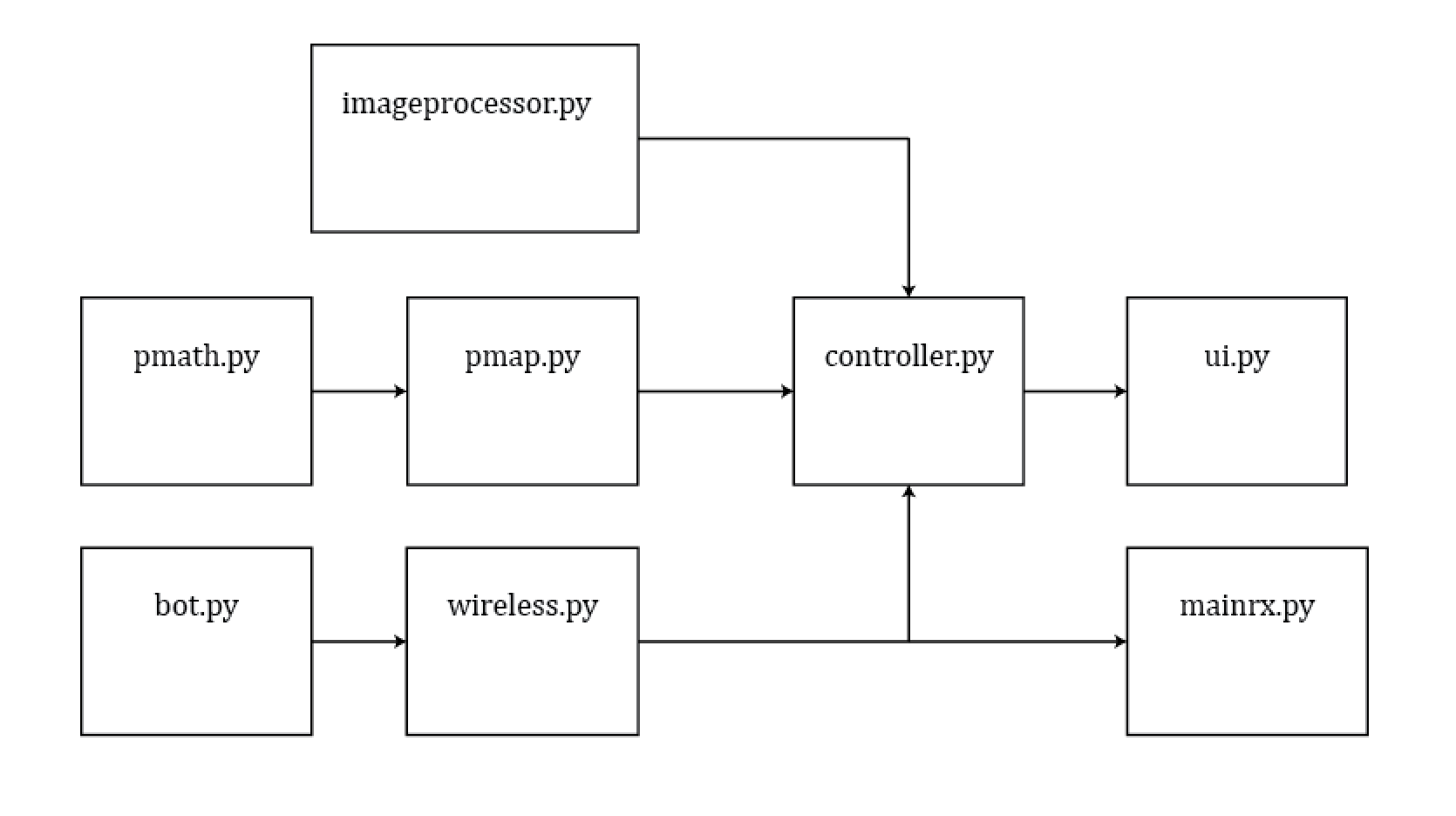
Figure 1: A high level diagram of the software. An arrow indicates an import.

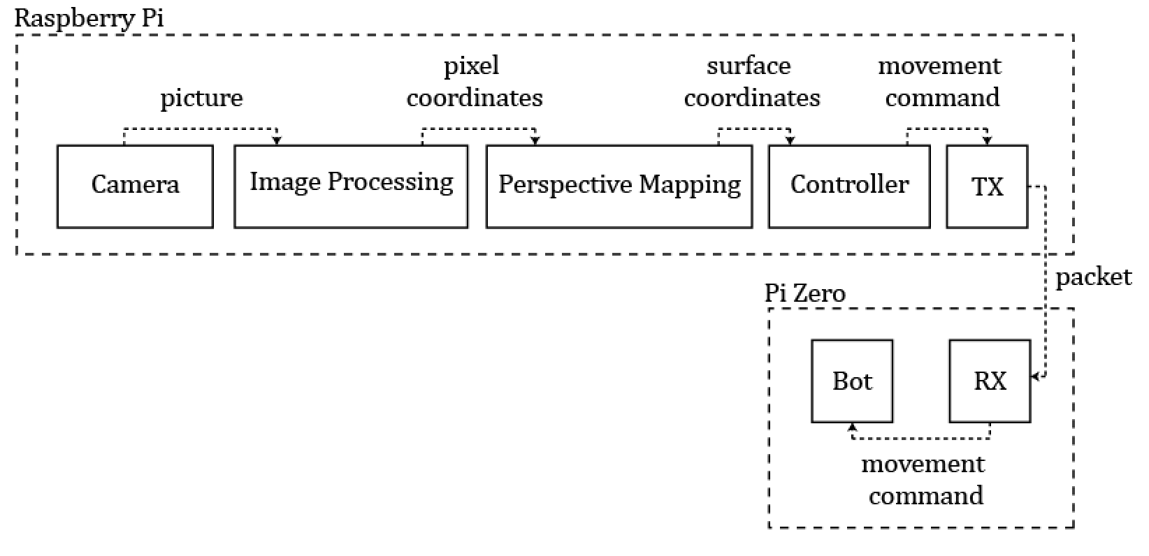
Figure 2: High level overview of how software components work together.

Our system works by first allowing the user to draw points on the PiTFT. When a point is drawn, it is automatically connected to the previous point with a line. After the user completes the drawing, the controller calibrates the perspective mapping software by having the robot move around in a predetermined fashion. Position of the robot is determined by a camera and three colored dots arranged in a triangle with a fixed distance of 1 inches between the centers of the dots. The drawn array of points is then sent to the controller which guides the robot from point to point, getting input from the perspective mapping software to determine the error in the bot’s trajectory and correct accordingly. The controller sends command packets to the Pi Zero (on the robot) via a socket connection to control the robot’s movements. Once the points are drawn, the user can decide to draw another picture for the robot to draw or quit the program. Each of these modules is described in detail below.

Perspective Mapping

The perspective mapping code can be found in the file ‘pmap.py’ and the main job of this module is to take in 3 points specified by pixel coordinates and convert that into 3D positions in the real world. The way this happens is by using a technique in computer graphics known as ray tracing. Essentially, the scene is modeled by a point for the camera and an image plane in front of the camera. Using this model, a 3D scene of objects can be projected onto the image plane by casting rays from the camera (the beginning point of the ray), through a pixel, and onto the scene where it will hit some object. The color of that object is then projected back onto the pixel.

Using this technique in reverse, we can cast rays from the camera to the input pixels and determine where the ray intersected the scene. Below is a diagram to make things a bit more clear:

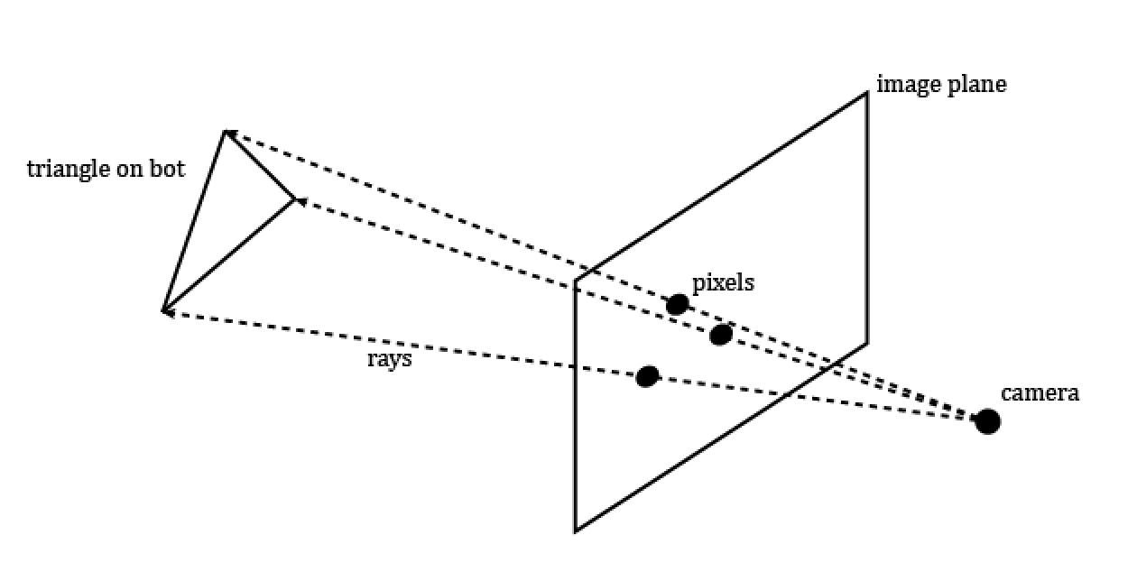
Figure 3: A simple diagram of ray tracing.

Because we know the distance is fixed between the sides of the triangle as 1 inches, this essentially boils down to a math problem of finding the likeliest length of the 3 rays with the 1 inch constraint. We can use the following equations (note that rays are represented as unit vectors):

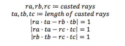
Our goal is to basically find the ta, tb, and tc  values that satisfies the above equations. To do this, we implemented a function that sweeps  ta , calculates the other length values based on this, and selects the  ta  value that yields a triangle that is closest to an equilateral triangle with side lengths of 1 inches. As it turns out, it is not quite enough to determine the 3D position of a triangle based on only the pixel coordinates: there are two solutions for each case. This is illustrated below:

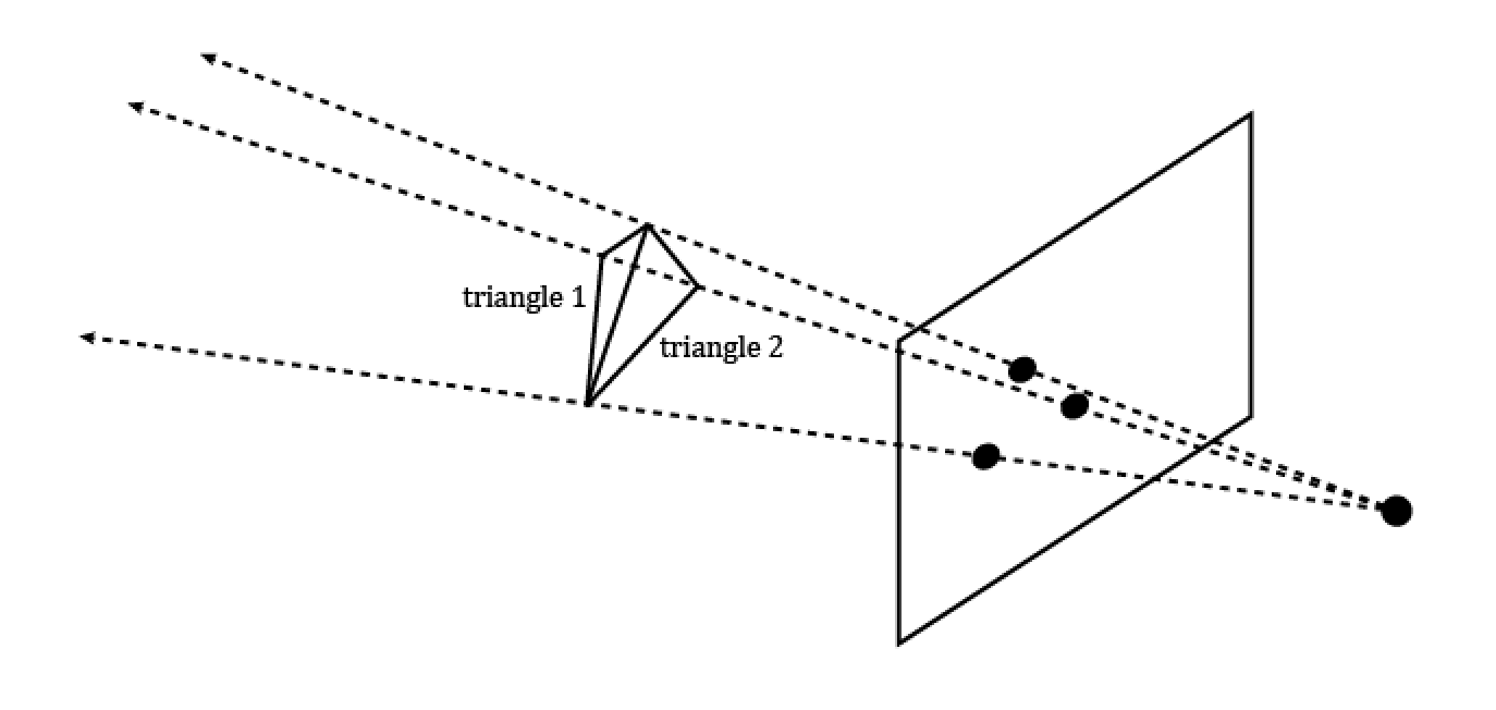
Figure 4: Two possible solutions for the same pixel coordinates.

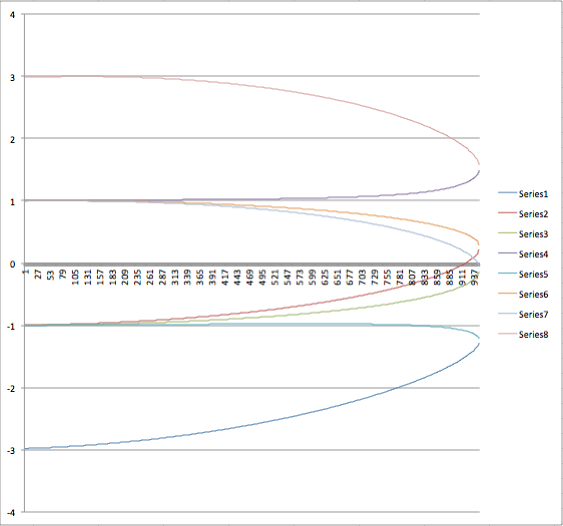
Figure 5: Graph of sweeping triangles. The y-axis here represents the error in upholding the condition that all triangle side lengths must be 1 inch and the x-axis represents the ta value. Two solutions can be seen where the error is nearly zero at x=~911 and another at x=~940.

Essentially, three points on a screen can be viewed as a triangle that is pointing towards you or a triangle pointing away from you. To figure out which of these was the desired solution, we needed to introduce some sort of calibration that would define the surface our robot was on and pick the triangle that was closest to the plane. Our calibration method takes a set of possible triangles and based on their surface normals, picks the surface normal that is closest to the most triangles in the set.

After the surface normal is established, future mappings become very easy since we simply need to intersect the rays with the surface to find the triangle. We can then determine the direction of the robot using the position of the three colors at each vertex of the triangle. Additionally, we use the first detected position of the robot as the origin of our coordinate system (which resides on the surface plane) and using the direction, determine plane axis vectors as well. Perspective mapping then becomes a O(1) operation and we simply need to solve the system of equations for ray intersection with the plane. We can then return the position and direction of the robot as 2D vectors.

One more component required to make this work was to take physical measurements of the setup. We needed to define a conversion factor from pixels to inches as well as measure the distance from the camera to the image plane. To do this, we simply took a picture of a ruler with the Pi camera, measured the distance from the camera to the surface the ruler was sitting on, and got the pixel to inch conversion factor by measuring the length of the ruler in the picture in pixels. The accuracy was not very important because we were mainly concerned with relative distances rather than absolute distances between points.

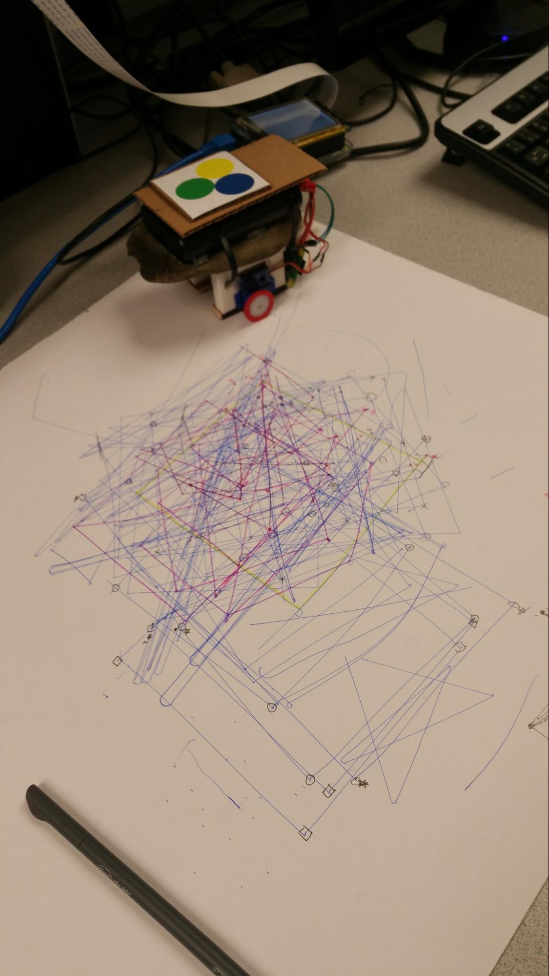
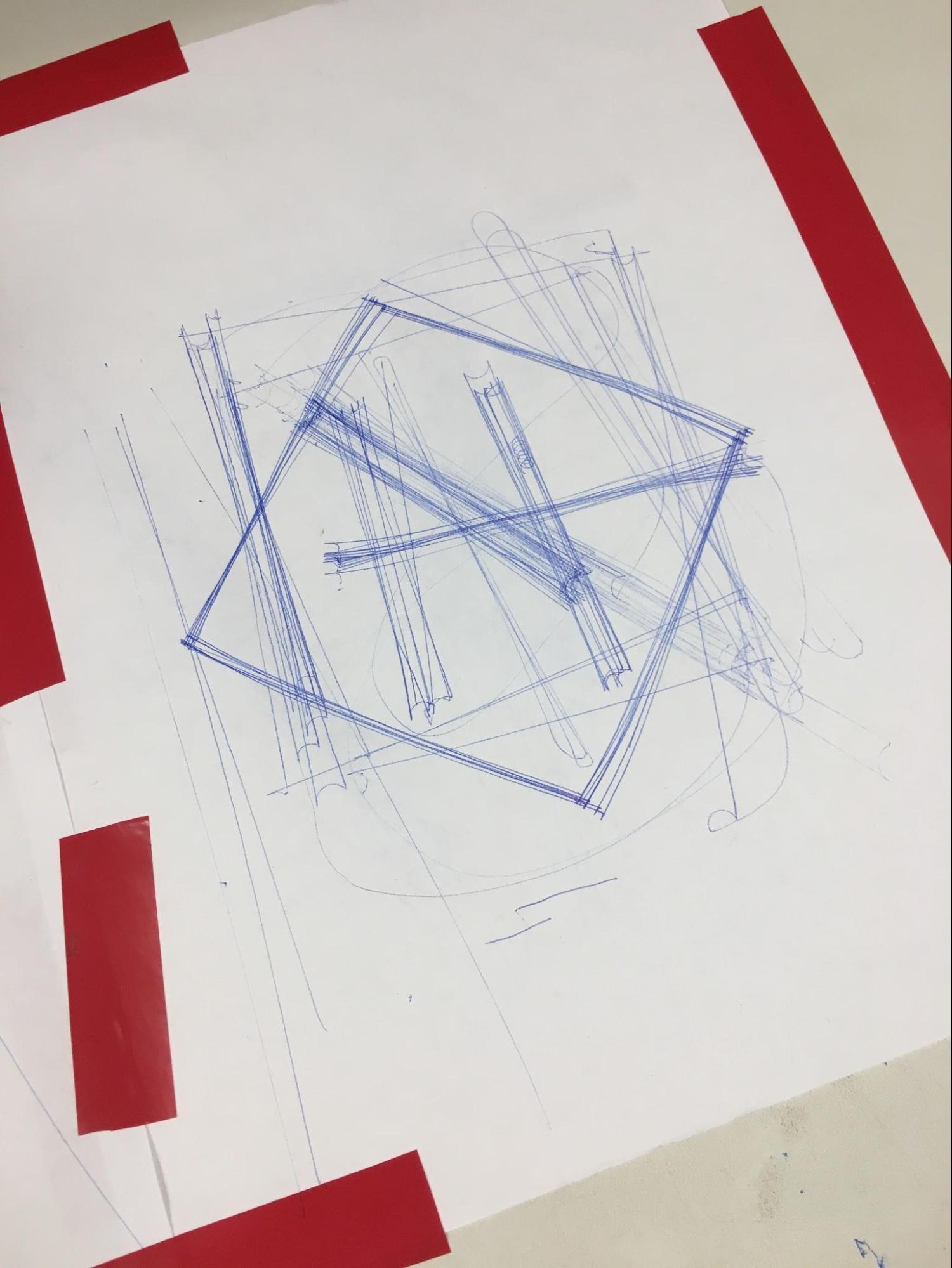
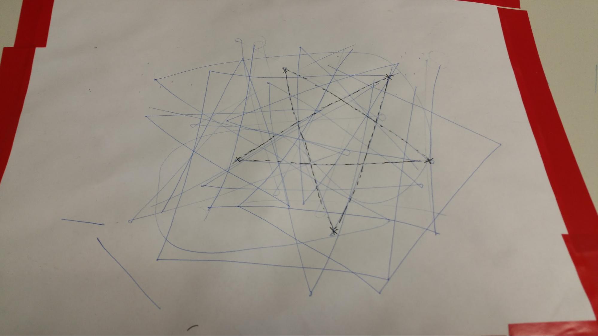
After this was completed, we tested by moving a paper on the table with three colored dots in a square in front of the camera and got the following result:

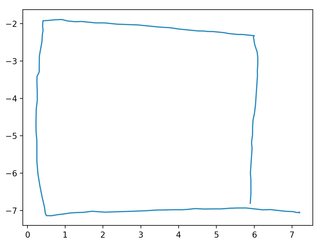
Figure 5: Perspective mapping, moving in a square.

Image Processing

The image processing code can be found in the file ‘imageprocessor.py’ and the main role of this module is to determine the position of the three colored dots on the screen in pixel coordinates by using the OpenCV library. To accomplish this, it needs to pick out the three colors reliably and ignore environmental noise that may be a similar color. We considered using LEDs since they are a light source and therefore would not be influenced by environmental factors such as dim lighting, but it turned out to be too bright for the Pi camera to detect as a color. We finally decided to print out 3 colored circles, 1 inch in diameter, on paper and place the paper on top of the robot for the camera to detect.

Our primary method of picking out the 3 circles was to use thresholding and generate binary images, one for each color. To do this, we specified the hue, saturation, and value ranges for each color and modified this across multiple tests to ensure that it worked for a wide range of environments while also minimizing the amount of noise present. Additionally, we needed to convert the input image from the standard RGB to HSV. Below is a table of the threshold ranges for each of the circles as well as the conversions to HSV:

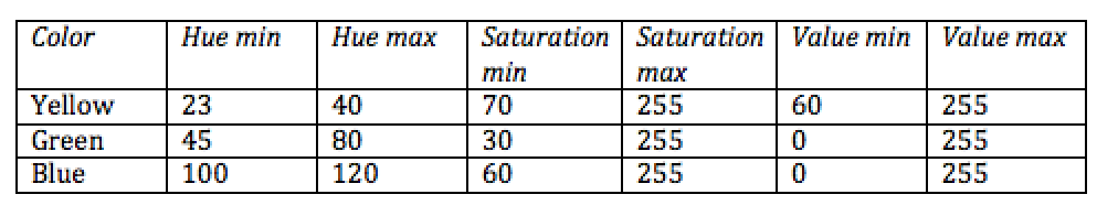
Table 1: Hue, saturation, and value ranges for thresholding. (Note: hue values range from 0 to 179 while saturation and value range from 0 to 255).

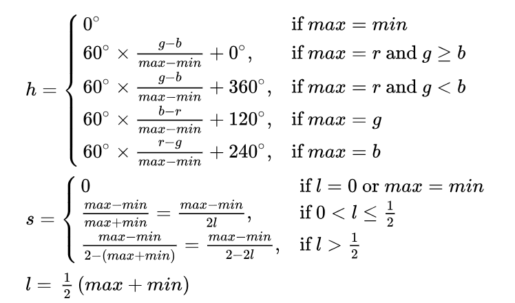
Figure 6: Equations to convert from RGB to HSV

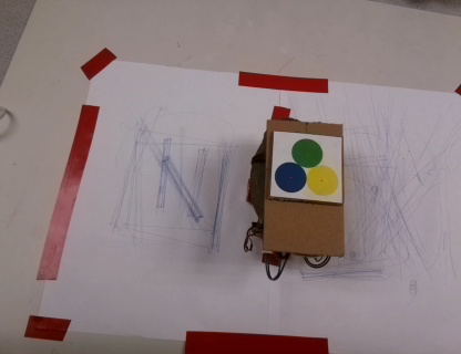
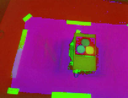
Figure 7: convert actual image from RGB to HSV

Much of this was trial and error, first testing for the nominal, well lit case and then moving on to shadowing the circles to see if it still worked. We found that converting to HSV helped a lot because hue would be constant regardless of the lighting conditions. One problem we encountered while testing was that depending on the time of day, there was varying levels of yellow and blue in the environment, namely a lot of blue and yellow that was highly unsaturated. To correct this, we adjusted the saturation so that those values would be cut out of the image.

Once binary images were produced, we needed to first filter out noise and locate the position of the three circles. To filter out noise, we first used OpenCV to find the contours of all the shapes in the binary image, and cut out contours which were below a specified size limit. We were then able to use moments to find the most circular shapes, as shown below:

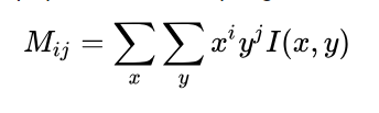
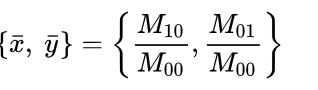
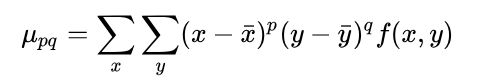
Figure 8: Moment equations

We then got the top three candidate circles for the binary images of each color (9 total), looked every possible combination of circles, and selected the group that was most tightly packed (closest together). Once the circles were determined, we again used the moments function to determine the centers of the circles. With this process, we were able to reliably locate the three circles in any lab lighting conditions and return their centers.

Wireless Communication

The job of the wireless communication module, found in the ‘wireless.py’ file, is to provide an interface that allows the Pi to communicate to the Pi Zero and remotely control the robot over the WiFi. It does this by establishing a TCP connection via the python socket module. The Pi acts like a server and sends commands as strings via a command code followed by a single argument for that command. The receiver then receives these commands one by one, looks up the command code, and executes the correct function on the actual robot. Below is a table of command codes we used for our robot:

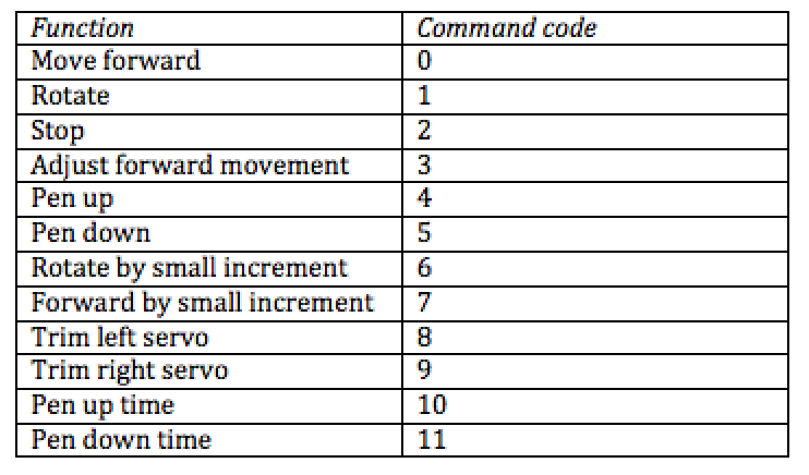
Table 2: Commands and their command codes.

Additionally, because the receive method of our socket blocked until it received the specified number of bytes causing erratic behavior, we specified a packet size of 50 bytes and executed commands one by one with no buffer (our connection was fast enough that commands were sent almost immediately). Our main concern for this was possible latencies between the server and the robot but because our packets were fairly small, we did not experience any noticeable delays.

Bot Controller

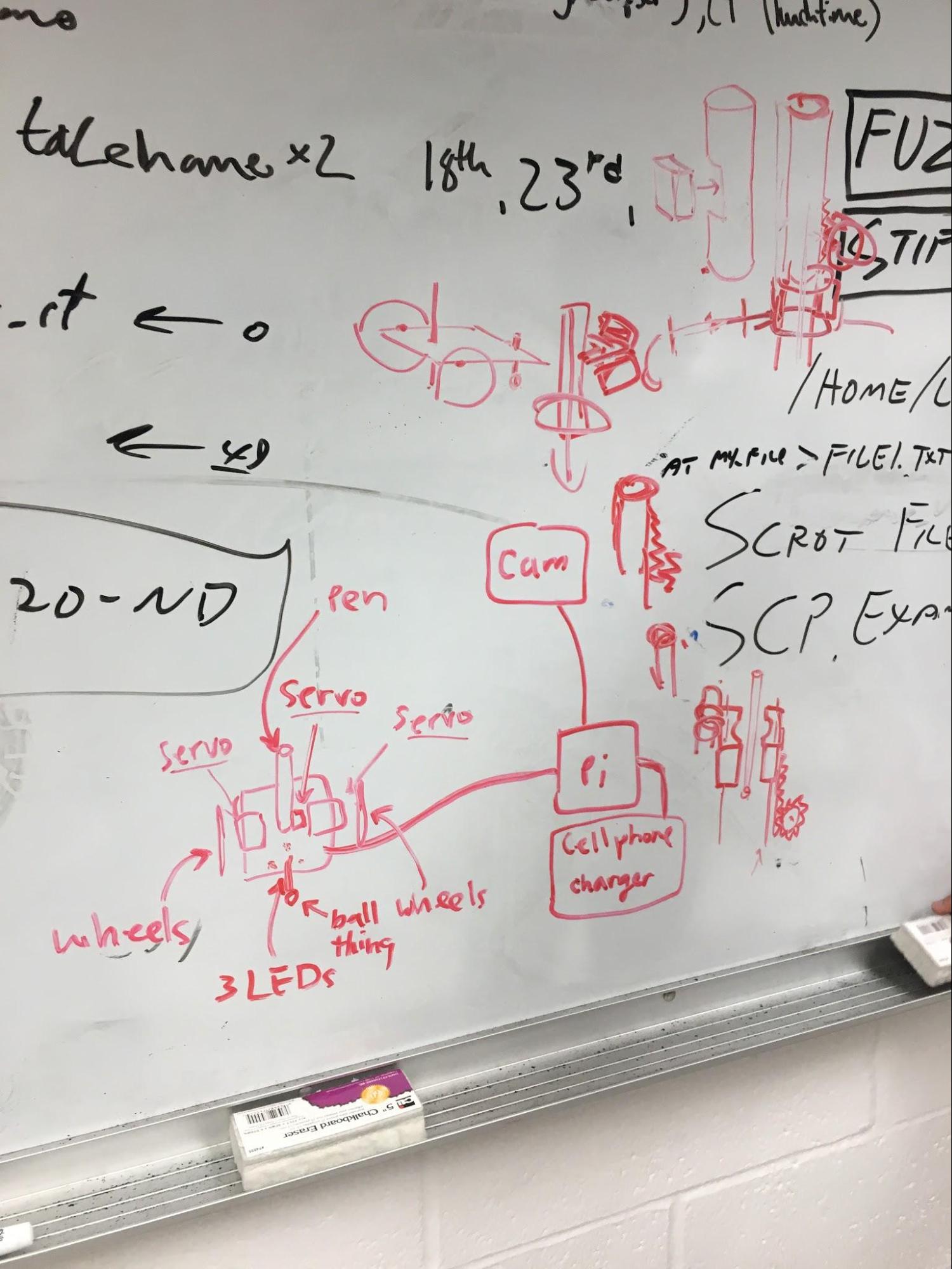
The job of the robot controller is to provide a library of functions that is able to move the robot in a variety of ways and can be found in the file ‘bot.py’. The robot itself is fairly simple, consisting of only 3 continuous rotation servos, two for the wheels and one for moving the pen up and down.

We first created a servo class that encapsulated functionality of a single servo. Our initial implementation consisted of using software PWM to control the servos, but we quickly realized that we needed to control the speed of the servos as accurately as possible. Due to this, we switched over to a hardware PWM implementation which greatly improved robot movement. The bot class provides several functions for moving the robot and their uses will be further discussed in the main controller section. Below is a table describing each function:

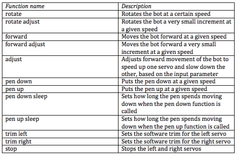
Table 3: Table showing all functions of the bot class.

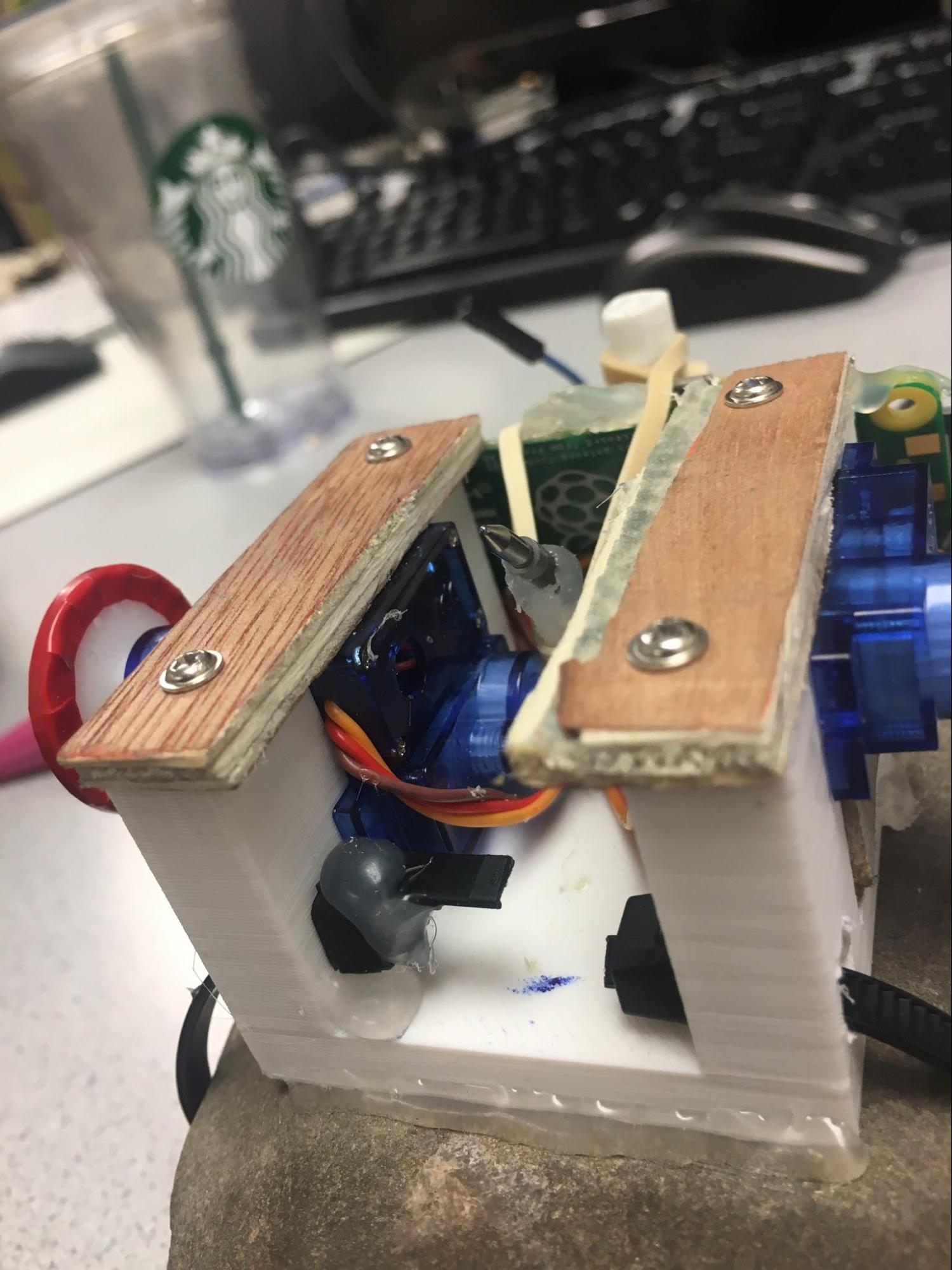
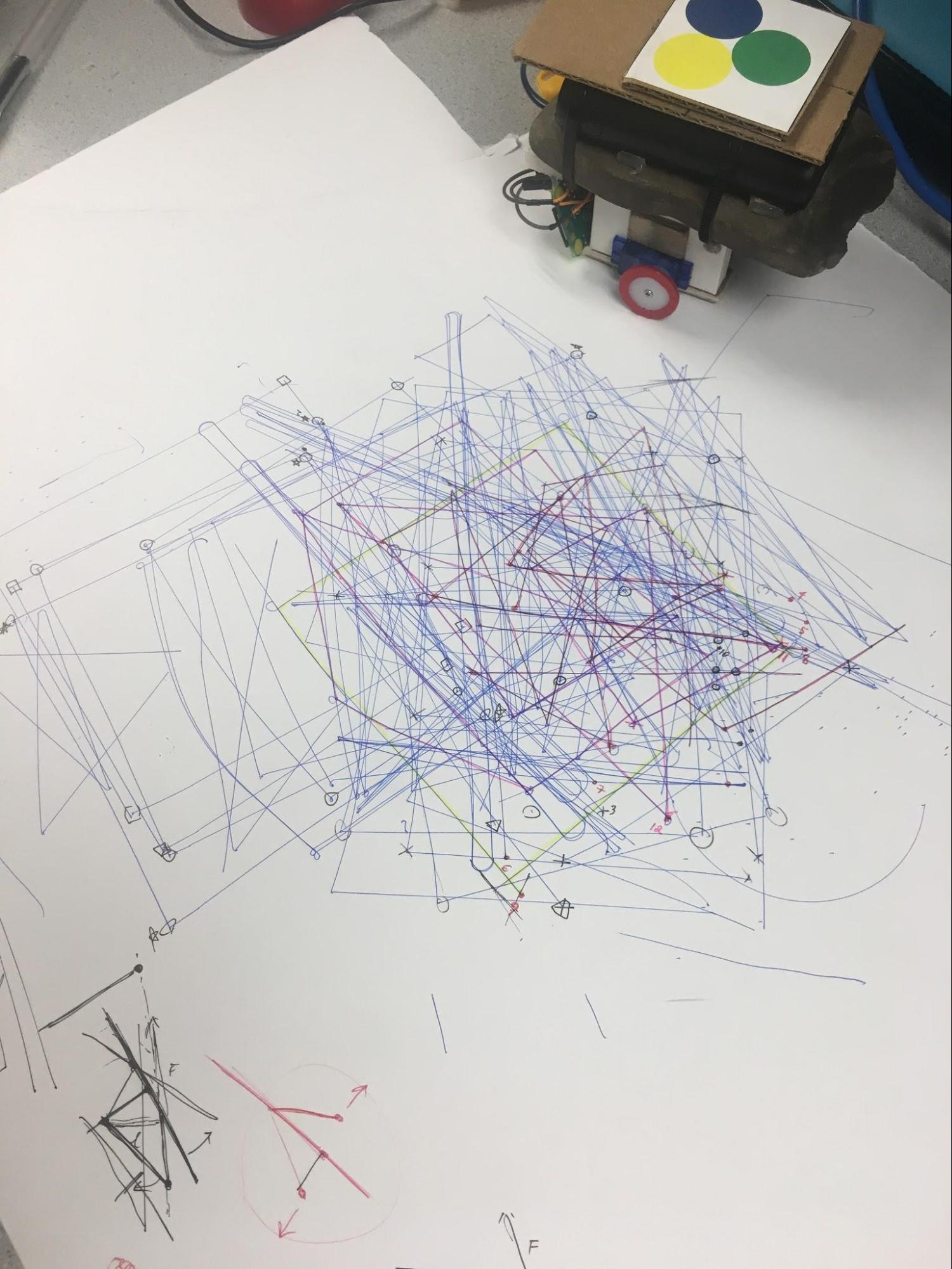
One of the main issues with the bot was getting the pen to draw reliably and as much in the center of the bot as possible. In our first iteration of the bot, the servo would push the pen down while also pushing the whole bot up so that the wheels were not touching the ground. To fix this, we needed a weight of some sort so we placed a rock on top of our bot to hold it in place. This also provided more friction between the wheels and the paper which improved mobility. Our bot can be seen in the figure below:

Figure 9: Pictures of our bot. The rubber band can be seen on the right and the rock can be seen on the left, providing a weight to hold the pen down.

Main Controller

The main controller (found in the file ‘controller.py’) is responsible for using the library functions provided by the image processor, perspective mapping, and wireless bot to guide the robot from point to point. Additionally, the controller contains all of the parameters for bot movement such as servo trimming, error tolerances, bot speed, and so on.

The controller first establishes a wireless connection with the bot, and calls functions that sets up static parameters of the bot including trim values for the left and right servos, pen up and pen down speed, and the length of time spent putting the pen up or down. After this, it starts a calibration routine that basically moves the bot in a predetermined sequence so that the perspective mapping software can determine the surface normal of the plane on which the bot is on. Once completed, the perspective mapping software can identify the position of the bot using the established surface normal and surface axes. The controller then starts the sequence of moving from point to point. A diagram of this process can be seen below:

Figure 10: Main sequence of events to draw from point to point.

As shown in Figure 10, triangle pixel coordinates are obtained from the image processor which is then passed to the perspective mapping to determine the position and direction of the bot on the surface plane and based on this information, the next movement of the bot is determined.

The movement of the bot was especially difficult since drawing needed to be as accurate as possible. To accomplish a high level of accuracy, we implemented a variety of tweaks: to move to a certain target point, the bot is rotated to within a certain tolerance (fairly large, about 40 degrees) towards the target point and then is rotated thereafter in very small increments until the target direction is reached. We only rotate in one direction since the servos are not perfectly calibrated (since they were both cheap and naturally have small differences in movement speed) and may rotate inaccurately in one direction but accurately in the other. We also increment in small amounts until we have just passed the target direction which we check by looking at the sign of the cross product between the two vectors. Moving forward works the same way where we move the bot forward towards the point to within a certain radius and then move forward in small increments until the target point has been just passed. We check this by looking at the sign of the dot product between the target direction and the bot direction.

Additionally, we implemented a variation of PID control (using just the proportional component) to guide the bot while it covers the distance to the target point to within a certain radius. Our error is based on the angle difference between the bot direction vector and direction vector from the bot to the target point. Based on this error, one of the servos is slowed down slightly while the other is sped up slightly to correct the error. We considered adding in the derivative and integral components but found that using only proportional worked well.

Figure 11: Diagram showing error for proportional control.

One of the main problems we had with the bot was the rate at which it could complete the sequence shown in Figure 10: often times, the overhead of the image processing and perspective mapping was enough for the controller to stop the bot later than desired, causing the bot to overshoot the desired location or direction. The reason we used the small rotational and forward adjustments was to correct this problem. We initially tried to decrease the servo speed but found that the slowest speed possible was still too fast for the system to catch it and stop it in time.

User Interface

The user interface code can be found in the file “ui.py” and essentially creates a simple interface on the PiTFT for the user to draw shapes. The user can use the 4 buttons to clear the drawing or quit the program (when there are no points), redo, undo, and complete the drawing and start drawing. Points can be placed on the canvas by using the touchscreen of the PiTFT. After the drawing is completed, a point array (of pixel coordinates) is passed to the controller and the bot begins drawing. The UI can be seen below:

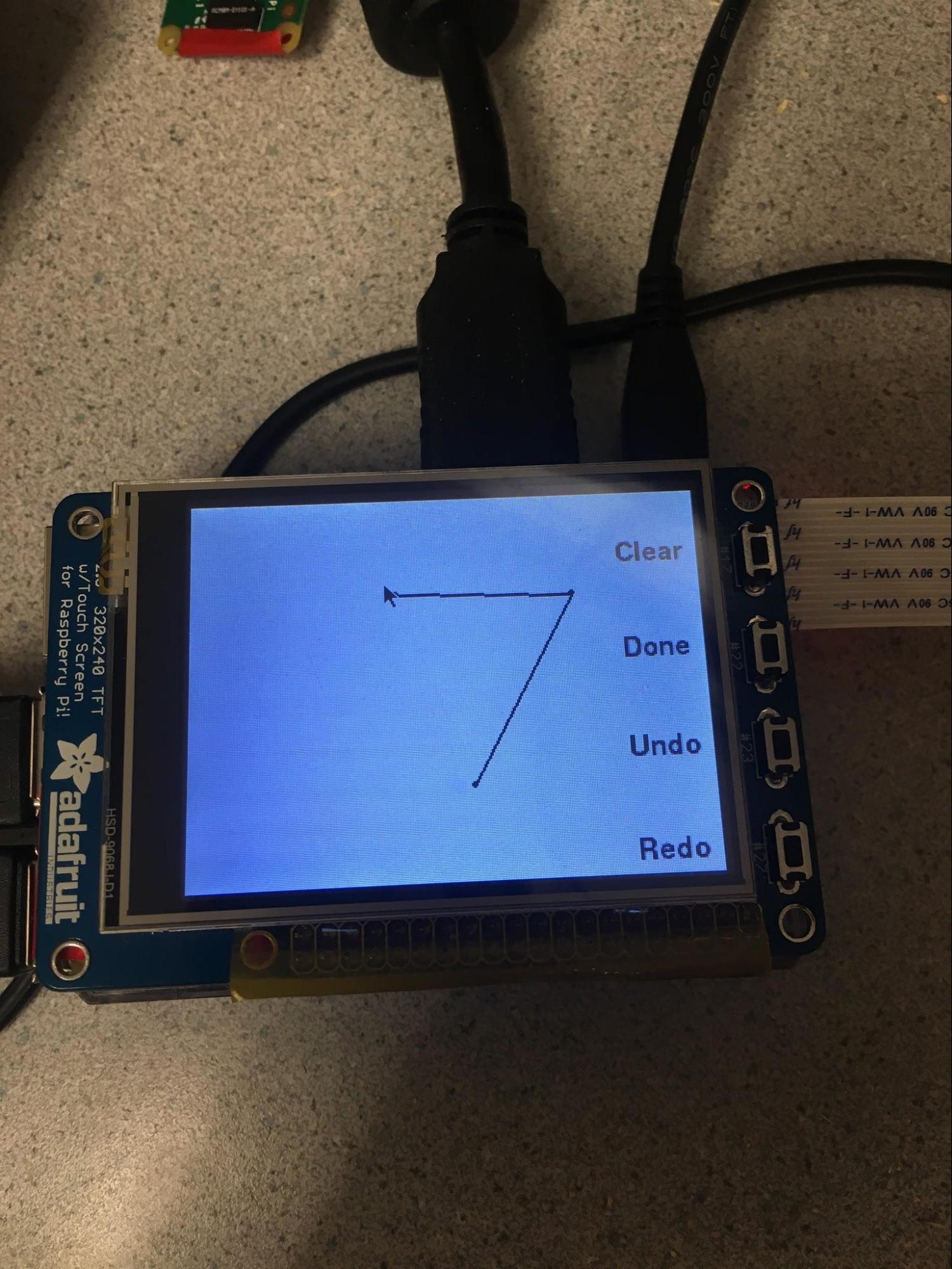
Figure 12: Picture of the user interface.

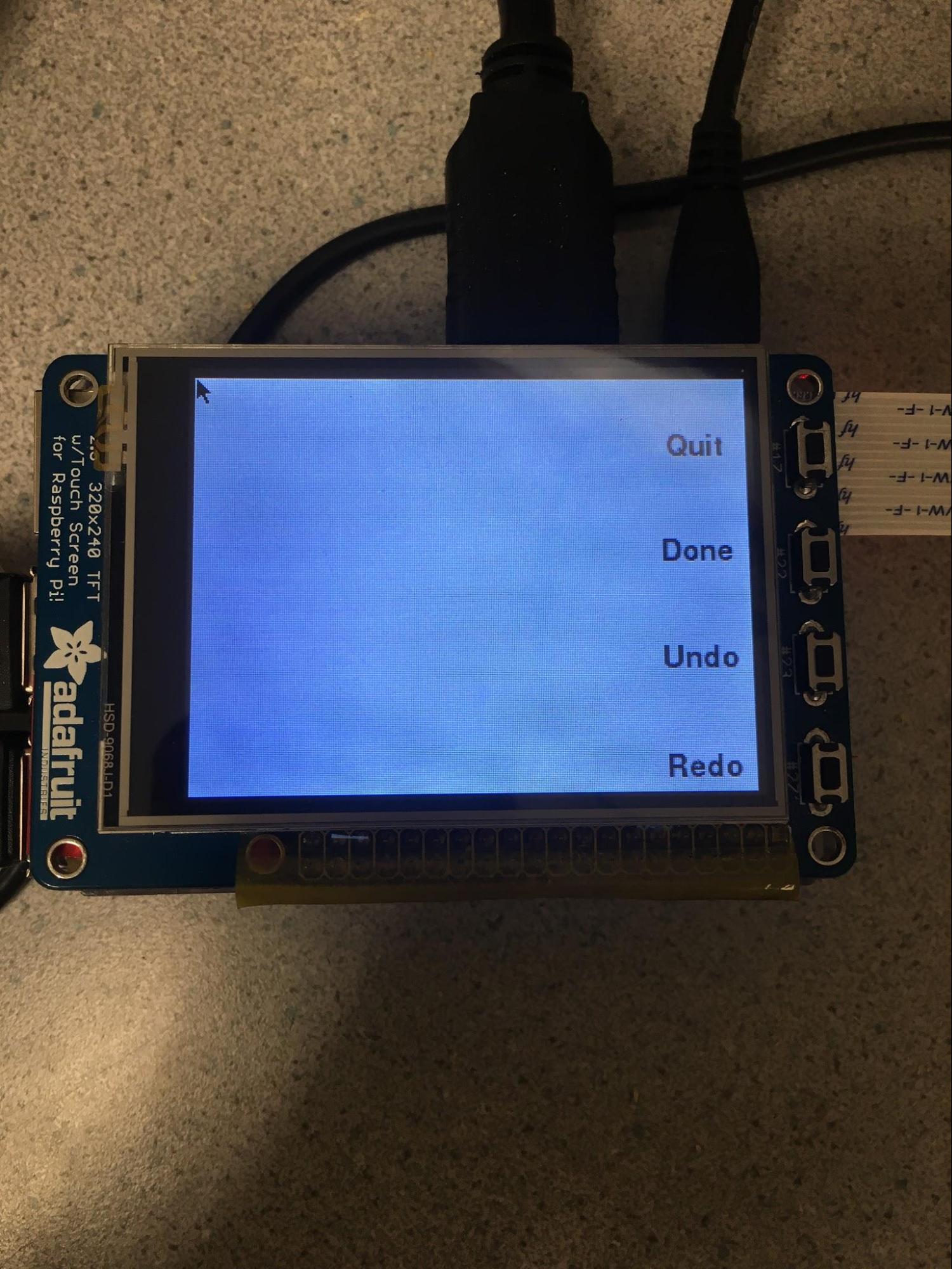
Figure 13: Another picture of the UI. The clear button changes to a quit button when the canvas is empty.

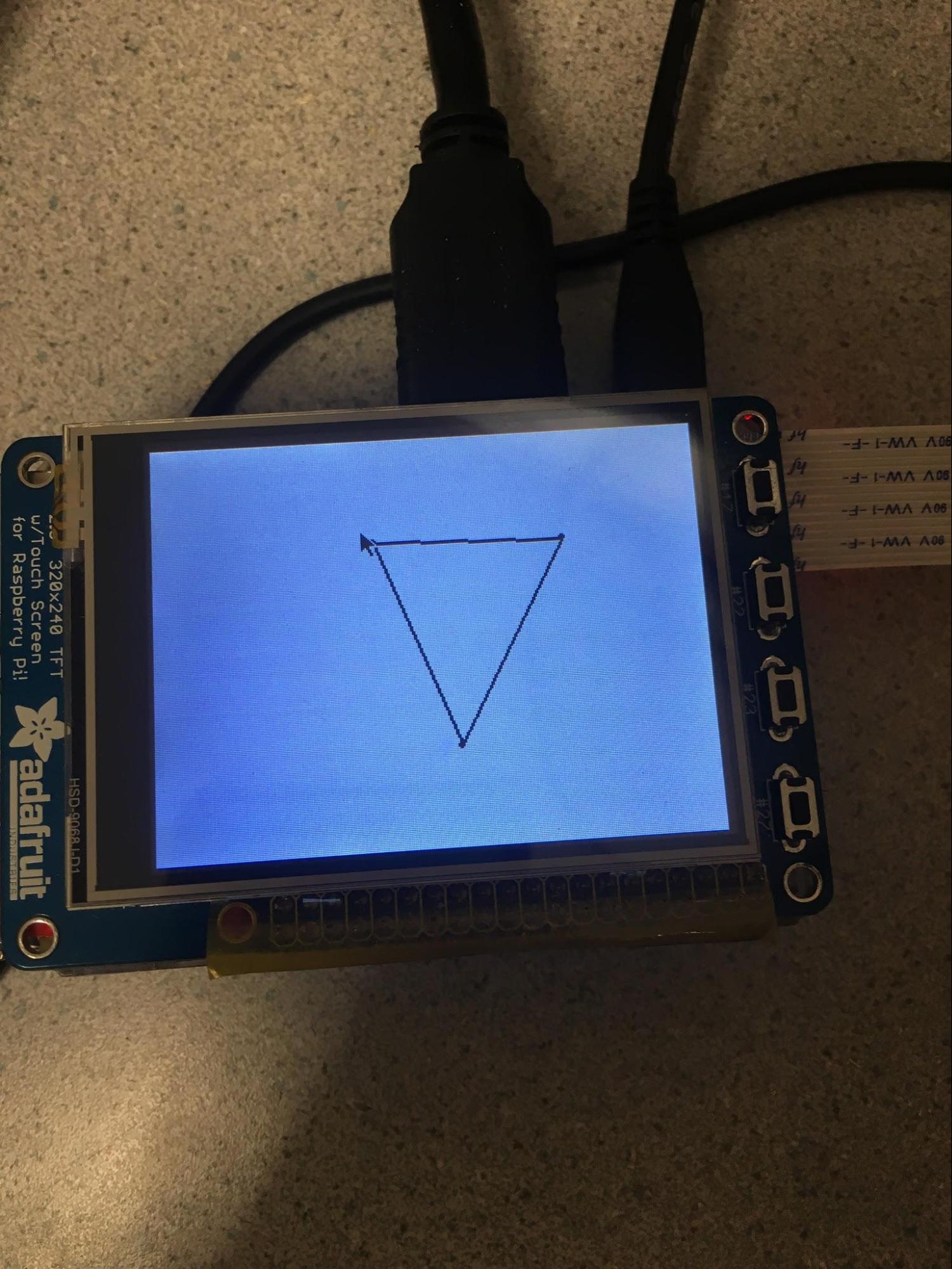
Figure 14: Side button text disappears after a few seconds of not pressing any buttons.


Results

Overall, our robot worked as expected: we were able to draw an image on the PiTFT, and have the robot draw a picture with fairly good accuracy, to within an inch of error. The completed robot is shown below:

Figure 15: Completed drawing robot.

Figure 16: Early sketches of the drawing bot.

Figure 17: Underside of the robot, showing the pen and rubber band.

A great deal of time was spent optimizing various components of the robot to increase accuracy. Some of these optimizations include decreasing the resolution of the screen so that more points could be mapped per second, decreasing the packet size from the original size of 1024 bytes to 50 bytes to decrease wireless latency, implementing an O(1) version of the perspective mapping after establishing the surface normal, and tweaking the robot settings such as the speed of the servos as well as applying software trim. Our improvements over time can be seen below:

Figure 18: drawing robot keep drawing straight line between two points. Lines on the right side are earliest lines. They gradually evolve to to the lines on the left side.

Figure 19: Drawing squares and lines. Accuracy was increased over time, as seen in the lighter square in the back vs the darker square in the front.

Figure 20: More testing, drawing a variety of shapes.

Our perspective mapping also worked as expected, as seen in a previous figure and worked fairly accurately, to within less than an inch of tolerance:

Figure 21: Perspective mapping a square.

Implementing the constant time solution greatly increased the granularity of movements for the robot and improved our controller substantially since it could detect slight movements. Additionally, we were able to sweep triangle distances and select the one with the smallest error. Below is a figure that shows the error as well as the two solutions that intersect the x-axis:

Figure 22: The y-axis represents the error in the triangles swept out by perspective mapping. As seen here, there are two solutions where the error is zero.

The final implementation of our image processor worked well, effectively ignoring environmental factors such as shadows and highlights, picking out the three colors, and producing binary images:

Figure 23: On the left is the original image and on the right is an HSV image encoded in RGB. Environmental factors cause highlights, and introduce extra colors such as blue hues in shadows and yellow hues on white surfaces. Red pixels can be seen in the centers of the three circles indicating that the image processor has correctly identified the centers of the circles.

Figure 24: The three binary images are shown here for yellow, blue, and green respectively.

Below is the final result of the bot. It can handle points that are close together fairly well as well as ones that are far apart. Both triangles begin and end at almost the same location (within less than an inch of tolerance).:

Figure 25: Some final drawings of the bot.


Conclusions

Overall, our robot worked as expected. We were able to reliably draw pictures with the camera setup and the user interface. I believe we did everything possible to optimize at the software level and our main limitations at the end were due to the hardware we used to build our robot. Our project mainly consisted of making small, incremental improvements to our software in each of the modules outlined above. For instance, for the bot module, we realized that using hardware PWM greatly improved the granularity in movement of the bot and for perspective mapping, figuring out the constant time solution to find the triangle improved granularity in the bot’s position and direction. If we were given this project for a second time, we would most likely try to research and invest in better components that would improve accuracy such as an encoder for the servos or camera with better lighting adjustment and resolution.


Future Work

The main bottleneck for our bot was the hardware we used. Our servos were very cheap and stopped moving when close to zero speed so much of the solutions we implemented was working around the hardware. Using better servos with a higher granularity of movement would greatly improve movement accuracy. Another limitation was the resolution of our camera. In order to do reduce the latency, we can change the pi camera to a better camera with a higher frame rate to higher resolution images which would allow us to more accurately determine the position and direction of the bot. The final bottleneck is the structure of our code. Changing to a multithreaded design may decrease latency and allow more frames to be processed per second. This is especially useful if we were to use higher resolution images.

Additionally, WiFi latency was fairly low but there were noticeable jitters when many people were on the network. Using Bluetooth for wireless connection instead of WiFi would possibly be a better solution, but we did not have the time to figure out how to use sockets using Bluetooth so we went with a WiFi connection. Another structural flaw was the mechanism to hold the pen in place. The rubber band that held the pen down would stretch out over the course of a day and start producing different results (e.g. the pen would draw faint lines). Given more time, we would have redesigned the structure to use a spring and move the pen up and down vertically rather than have it rotate down onto the paper like we did.


Parts List


References

PiCamera Document
Tower Pro Servo Datasheet
Pigpio Library
R-Pi GPIO Document

Code Appendix

  1
  2
  3
  4
  5
  6
  7
  8
  9
 10
 11
 12
 13
 14
 15
 16
 17
 18
 19
 20
 21
 22
 23
 24
 25
 26
 27
 28
 29
 30
 31
 32
 33
 34
 35
 36
 37
 38
 39
 40
 41
 42
 43
 44
 45
 46
 47
 48
 49
 50
 51
 52
 53
 54
 55
 56
 57
 58
 59
 60
 61
 62
 63
 64
 65
 66
 67
 68
 69
 70
 71
 72
 73
 74
 75
 76
 77
 78
 79
 80
 81
 82
 83
 84
 85
 86
 87
 88
 89
 90
 91
 92
 93
 94
 95
 96
 97
 98
 99
100
101
102
103
104
105
106
107
108
109
110
111
112
113
114
115
116
117
118
119
120
121
122
123
124
125
126
127
128
129
130
131
132
133
134
135
136
137
138
139
140
141
142
143
144
145
146
147
148
149
150
151
152
153
154
155
# pmath.py
#
# Provides vector math functions for perspective mapping

class Vec3(object):
  def __init__(self, x, y, z):
    self.x = float(x)
    self.y = float(y)
    self.z = float(z)

  def clone(self):
    return Vec3(self.x, self.y, self.z)

  def cross(self, other):
    ax, ay, az = self.x, self.y, self.z
    bx, by, bz = other.x, other.y, other.z
    return Vec3(ay*bz - az*by, az*bx - ax*bz, ax*by - ay*bx)

  def mag(self):
    return (self.x ** 2 + self.y ** 2 + self.z ** 2) ** .5

  def normalize(self):
    m = self.mag()
    self.x /= m
    self.y /= m
    self.z /= m
    return self

  def dist_to(self, other):
    return (self - other).mag()

  def vals(self):
    return (self.x, self.y, self.z)

  def __mul__(self, other):
    if type(other) == Vec3:
      return self.x * other.x + self.y * other.y + self.z * other.z
    return Vec3(self.x * other, self.y * other, self.z * other)

  def __div__(self, other):
    return Vec3(self.x / other, self.y / other, self.z / other)

  def __add__(self, other):
    assert type(other) == Vec3
    return Vec3(self.x + other.x, self.y + other.y, self.z + other.z)

  def __sub__(self, other):
    assert type(other) == Vec3
    return Vec3(self.x - other.x, self.y - other.y, self.z - other.z)

  def __rsub__(self, other):
    assert type(other) == Vec3
    return Vec3(other.x - self.x, other.y - self.y, other.z - self.z)

  __rmul__ = __mul__
  __radd__ = __add__

  def __str__(self):
    return "<%f, %f, %f>" % (self.x, self.y, self.z)

class Vec2(object):
  def __init__(self, x, y):
    self.x = float(x)
    self.y = float(y)

  def clone(self):
    return Vec2(self.x, self.y)

  def cross(self, other):
    return self.x * other.y - other.x * self.y

  def mag(self):
    return (self.x ** 2 + self.y ** 2) ** .5

  def normalize(self):
    m = self.mag()
    self.x /= m
    self.y /= m
    return self

  def dist_to(self, other):
    return (self - other).mag()

  def vals(self):
    return (self.x, self.y)

  def __mul__(self, other):
    if type(other) == Vec2:
      return self.x * other.x + self.y * other.y
    return Vec2(self.x * other, self.y * other)

  def __div__(self, other):
    return Vec2(self.x / other, self.y / other)

  def __add__(self, other):
    assert type(other) == Vec2
    return Vec2(self.x + other.x, self.y + other.y)

  def __sub__(self, other):
    assert type(other) == Vec2
    return Vec2(self.x - other.x, self.y - other.y)

  def __rsub__(self, other):
    assert type(other) == Vec2
    return Vec2(other.x - self.x, other.y - self.y)

  __rmul__ = __mul__
  __radd__ = __add__

  def __str__(self):
    return "<%f, %f>" % (self.x, self.y)

class PFunction(object):
  def __init__(self, f, eps):
    self.f = f
    self.eps = eps

  def __call__(self, x):
    return self.f(x)

  # Finds the slope of the function at a certain point.
  def slope(self, x):
    prev = self.f(x)
    nxt = self.f(x - self.eps)
    if None in [prev, nxt]:
      return None
    return (self.f(x) - self.f(x - self.eps)) / self.eps

  # Finds the end of the function in a certain range and return 
  # the input value.
  def findEnd(self, a, b):
    left, right = a, b
    while right - left > self.eps:
      middle = (left + right) / 2
      if self.f(middle) == None:
        right = middle
      else:
        left = middle
    return left

  # Finds the minimum of a function given a domain interval and
  # returns the input value for which the function is minimum. Works
  # only for unimodal functions.
  def findMin(self, a, b):
    left, right = a, b
    while right - left > self.eps:
      middle = (left + right) / 2
      smiddle = self.slope(middle)
      if smiddle == None:
        return None
      if smiddle > 0:
        right = middle
      else:
        left = middle
    return (left + right) / 2
  1
  2
  3
  4
  5
  6
  7
  8
  9
 10
 11
 12
 13
 14
 15
 16
 17
 18
 19
 20
 21
 22
 23
 24
 25
 26
 27
 28
 29
 30
 31
 32
 33
 34
 35
 36
 37
 38
 39
 40
 41
 42
 43
 44
 45
 46
 47
 48
 49
 50
 51
 52
 53
 54
 55
 56
 57
 58
 59
 60
 61
 62
 63
 64
 65
 66
 67
 68
 69
 70
 71
 72
 73
 74
 75
 76
 77
 78
 79
 80
 81
 82
 83
 84
 85
 86
 87
 88
 89
 90
 91
 92
 93
 94
 95
 96
 97
 98
 99
100
101
102
103
104
105
106
107
108
109
110
111
112
113
114
115
116
117
118
119
120
121
122
123
124
125
126
127
128
129
130
131
132
133
134
135
136
137
138
139
140
141
142
143
144
145
146
147
148
149
150
151
152
153
154
155
156
157
158
159
160
161
162
163
164
165
166
167
168
169
170
171
172
173
174
175
176
177
178
179
180
181
182
183
184
185
186
187
188
189
190
191
192
193
194
195
196
197
198
199
200
201
202
203
204
205
206
207
208
209
210
211
212
213
214
215
216
217
218
219
220
221
222
223
224
225
226
227
228
229
230
231
232
233
234
235
236
237
238
239
240
241
242
243
244
245
246
247
248
249
250
251
252
253
254
255
256
257
258
259
260
261
262
263
264
265
266
267
268
269
270
271
272
273
274
275
276
277
278
279
280
281
282
283
284
285
286
287
288
289
290
291
292
293
294
295
296
297
298
299
300
301
302
303
304
305
306
307
308
309
310
311
312
313
314
315
316
317
318
319
320
321
322
323
324
325
326
327
328
329
330
331
332
333
334
335
336
337
338
339
340
341
342
343
344
345
346
347
348
349
350
351
352
# pmap.py
#
# Perspective mapping from screen coordinates to surface coordinates

from pmath import *
import numpy as np
from numpy.linalg import inv

# constants
TRIANGLE_UNITS  = 1.0
DISTANCE_TO_CAM = 14.625
P2U             = 15.0 / 361.411
DISTANCE_MAX    = 100.0
IMG_WIDTH       = 416
IMG_HEIGHT      = 320
PIC_WIDTH       = 320
PIC_HEIGHT      = 240

class Triangle(object):
  def __init__(self, r, g, b):
    self.r = r
    self.g = g
    self.b = b
    self.center = (r + g + b) / 3.0
    self.normal = (b - r).cross(g - r).normalize()
    self.direction = (g - (r + b) / 2).normalize()
  
  def __str__(self):
    return "[%s, %s]" % (str(self.center), str(self.normal))

# This class provides the functions necessary to convert screen space 
# coordinates (e.g. pixel coordinates) into coordinates in the 3D world as well as
# 2D coordinates on paper space (e.g. the plane on which the robot travels).
#
# Note: before perspective mapping can be utilized, the surface normal
# must be calibrated. This is done by:
#  self.addCalibration -> ... -> self.addCalibration -> self.calibrateSurfaceNormal -> self.initSurface
class PMap(object):
  def __init__(self, epsx, epsy):
    # Epsilon values
    self.epsx = epsx
    self.epsy = epsy

    # Direction vectors
    self.ra = None
    self.rb = None
    self.rc = None

    # Surface variables
    self.calibrate = []
    self.start = None #Vec3(-4.001322, -1.373553, 10.475298)#None
    self.surfaceNormal = None #Vec3(0.105336, 0.112570, -0.983134)#None
    self.surfaceX = None #Vec3(-0.994370, 0.016962, -0.104598)#None
    self.surfaceY = None #Vec3(0.004925, 0.993437, 0.114278)#None
    self.framex = 0.15
    self.framey = 0.15

  # Input vectors in pixel coordinates
  def setPoints(self, p1, p2, p3):
    p1x, p1y = p1
    p2x, p2y = p2
    p3x, p3y = p3

    # Transform pixel coordinates to be centered at the origin
    p1x, p1y = p1x - float(IMG_WIDTH / 2), float(IMG_HEIGHT / 2) - p1y
    p2x, p2y = p2x - float(IMG_WIDTH / 2), float(IMG_HEIGHT / 2) - p2y
    p3x, p3y = p3x - float(IMG_WIDTH / 2), float(IMG_HEIGHT / 2) - p3y

    # Convert pixels to units and set z coordinate
    p1 = P2U * Vec3(p1x, p1y, 0.0)
    p2 = P2U * Vec3(p2x, p2y, 0.0)
    p3 = P2U * Vec3(p3x, p3y, 0.0)
    p1.z = DISTANCE_TO_CAM
    p2.z = DISTANCE_TO_CAM
    p3.z = DISTANCE_TO_CAM

    # Normalize and use as direction vectors
    self.ra = p1.normalize()
    self.rb = p2.normalize()
    self.rc = p3.normalize()

  # Traces out a triangle for a given ta value and returns
  # the path that it took.
  def generateDiff(self, t):
    def genHelper(t, i, path):
      if i == 3:
        return [path + [t]]
      if t == None:
        return genHelper(None, i + 1, path + [None]) + genHelper(None, i + 1, path + [None])

      rab = self.ra * self.rb
      rcb = self.rc * self.rb
      rac = self.ra * self.rc
      arr = [rab, rcb, rac]
      left = t * arr[i]
      right = t * t * (arr[i] * arr[i] - 1) + 1

      if right < 0:
        return genHelper(None, i + 1, path + [None]) + genHelper(None, i + 1, path + [None])

      plus = left + right ** .5
      minus = left - right ** .5
      return genHelper(plus, i + 1, path + [t]) + genHelper(minus, i + 1, path + [t])
    return genHelper(t, 0, [])

  # Returns a function that traces a specific triangle path and returns 
  # an array containing the path that it took.
  def makeTraceFunc(self, path):
    f = lambda t: self.generateDiff(t)[path]
    return PFunction(f, self.epsx)

  # Returns a function that traces a specific triangle path for a given
  # ta and returns abs(ta - looped around ta)
  def makeDiffFunc(self, path):
    def f(t):
      res = self.generateDiff(t)[path]
      if res[-1] == None:
        return None
      return abs(res[0] - res[-1])
    return PFunction(f, self.epsx)

  # Returns a function that traces a specific triangle path for a given
  # ta and returns ta - looped around ta
  def makeSDiffFunc(self, path):
    def f(t):
      res = self.generateDiff(t)[path]
      if res[-1] == None:
        return None
      return res[0] - res[-1]
    return PFunction(f, self.epsx)

  # Sweeps all diff function paths with a certain step size and prints out
  # the resulting values. Can copy/paste into excel to graph. 
  def sweepTriangles(self, step):
    funcs = []
    for i in range(8):
      funcs += [self.makeSDiffFunc(i)]
    
    i = 0
    s = ""
    while i < (1 - (self.ra * self.rb) ** 2) ** -.5:
      s2 = ""
      for f in funcs:
        res = f(i)
        s2 += str(' ' if res == None else res) + '\t'
      s += s2 + '\n'
      i += step
    print s

  # Finds possible triangles within an epsilon value and
  # returns array of corresponding ta, tb, and tc.
  def findTriangles(self):
    mins = []
    for i in range(8):
      f = self.makeDiffFunc(i)
      trace = self.makeTraceFunc(i)
      end = f.findEnd(0.0, DISTANCE_MAX)
      m = f.findMin(0.0, end)
      if m == None:
        continue
      if None in trace(m):
        continue
      mins += [(f(m), trace(m))]

    mins = filter(lambda x: x[0] < self.epsy, mins)
    mins = map(lambda x: x[1], mins)
    triangles = []
    for tri in mins:
      r, g, b, _ = tri
      r, g, b = self.ra * r, self.rb * g, self.rc * b
      triangles += [Triangle(r, g, b)]
    return triangles

  # Finds triangle whose normal is closest to the established
  # surface normal.
  def getClosestTriangle(self, arr):
    return min(arr, key=lambda t: t.normal.dist_to(self.surfaceNormal))

  # Adds possible triangles to the calibration
  def addCalibration(self, p1, p2, p3):
    self.setPoints(p1, p2, p3)
    triangles = self.findTriangles()
    self.calibrate += triangles

  # Given a list of triangles, finds the surface normal that is 
  # closest to all triangle normals.
  def calibrateSurfaceNormal(self):
    bin1norm = None
    bin1pts = []
    bin2norm = None
    bin2pts = []
    for i in self.calibrate:
      if bin1norm == bin2norm == None:
        bin1norm = i.normal
        bin1pts += [i.center]
      elif bin2norm == None:
        bin2norm = i.normal
        bin2pts += [i.center]
      else:
        one = bin1norm.dist_to(i.normal)
        two = bin2norm.dist_to(i.normal)
        if one < two:
          bin1norm = (bin1norm + i.normal) / 2
          bin1pts += [i.center]
        else:
          bin2norm = (bin2norm + i.normal) / 2
          bin2pts += [i.center]

    bin1 = 0
    for i in range(len(bin1pts) - 1):
      bin1 += abs((bin1pts[i] - bin1pts[i + 1]) * bin1norm)
    bin2 = 0
    for i in range(len(bin2pts) - 1):
      bin2 += abs((bin2pts[i] - bin2pts[i + 1]) * bin2norm)

    self.surfaceNormal = bin1norm if bin1 < bin2 else bin2norm

  # Sets starting position in 3D space
  def initSurface(self, p1, p2, p3):
    triangle = self.perspectiveMap(p1, p2, p3)
    self.start = triangle.center
    self.surfaceX = triangle.direction.cross(self.surfaceNormal).normalize()
    self.surfaceY = self.surfaceNormal.cross(self.surfaceX).normalize()

  # Resets calibration array
  def resetCalibration(self):
    self.calibrate = []

  # Finds triangle in 3D space relative to the camera.
  def perspectiveMap(self, p1, p2, p3):
    self.setPoints(p1, p2, p3)
    ts = self.findTriangles()
    return self.getClosestTriangle(ts)

  # Finds position on the surface plane relative to the starting position
  # and returns 2D coordinates and the direction vector.
  def surfaceMap(self, p1, p2, p3):
    triangle = self.perspectiveMap(p1, p2, p3)
    p = triangle.center - self.start
    position = Vec2(self.surfaceX * p, self.surfaceY * p)
    d = triangle.direction
    direction = Vec2(self.surfaceX * d, self.surfaceY * d).normalize()
    return (position, direction)
  
  # Does the same thing as surfaceMap in O(1) time.
  def surfaceMapFast(self, p1, p2, p3):
    self.setPoints(p1, p2, p3)
    ramat = np.matrix([
      [self.surfaceX.x, self.surfaceY.x, -self.ra.x],
      [self.surfaceX.y, self.surfaceY.y, -self.ra.y],
      [self.surfaceX.z, self.surfaceY.z, -self.ra.z]
    ])
    rbmat = np.matrix([
      [self.surfaceX.x, self.surfaceY.x, -self.rb.x],
      [self.surfaceX.y, self.surfaceY.y, -self.rb.y],
      [self.surfaceX.z, self.surfaceY.z, -self.rb.z]
    ])
    rcmat = np.matrix([
      [self.surfaceX.x, self.surfaceY.x, -self.rc.x],
      [self.surfaceX.y, self.surfaceY.y, -self.rc.y],
      [self.surfaceX.z, self.surfaceY.z, -self.rc.z]
    ])
    o = np.array([[self.start.x], [self.start.y], [self.start.z]])
    ra = ramat.I * o
    rb = rbmat.I * o
    rc = rcmat.I * o
    ra = Vec2(ra[0], ra[1])
    rb = Vec2(rb[0], rb[1])
    rc = Vec2(rc[0], rc[1])
    position = (ra + rb + rc) / 3
    direction = (rb - (ra + rc) / 2).normalize()
    return (position, direction)

  def surfaceMapSingle(self, p):
    px, py = p

    # Transform pixel coordinates to be centered at the origin
    px, py = px - float(IMG_WIDTH / 2), float(IMG_HEIGHT / 2) - py

    # Convert pixels to units and set z coordinate
    p = P2U * Vec3(px, py, 0.0)
    p.z = DISTANCE_TO_CAM

    # Normalize and use as direction vectors
    r = p.normalize()

    # Intersect with surface
    rmat = np.matrix([
      [self.surfaceX.x, self.surfaceY.x, -r.x],
      [self.surfaceX.y, self.surfaceY.y, -r.y],
      [self.surfaceX.z, self.surfaceY.z, -r.z]
    ])
    o = np.array([[self.start.x], [self.start.y], [self.start.z]])
    r = rmat.I * o
    return Vec2(r[0], r[1])

  def findBounds(self):
    # Get 2D coordinates of edges of the screen
    points = [
      (        0, IMG_HEIGHT),
      (        0,          0),
      (IMG_WIDTH,          0),
      (IMG_WIDTH, IMG_HEIGHT)
    ]
    points = map(self.surfaceMapSingle, points)
    bl, tl, tr, br = points

    print "bl", bl
    print "tl", tl
    print "tr", tr
    print "br", br
    print

    # Find bounds and adjust
    bl.x = max(bl.x, tl.x)
    tl.x = max(bl.x, tl.x)
    tr.x = min(tr.x, br.x)
    br.x = min(tr.x, br.x)
    tl.y = max(tl.y, tr.y)
    tr.y = max(tl.y, tr.y)
    bl.y = min(bl.y, br.y)
    br.y = min(bl.y, br.y)

    xoffset = self.framex * abs(bl.x - br.x)
    yoffset = self.framey * abs(bl.y - tl.y)
    bloffset = Vec2(xoffset, -yoffset)
    troffset = Vec2(-xoffset, yoffset)

    return bl + bloffset, tr + troffset

  def mapPicture(self, points):
    # Fit picture space into the bounds of the surface
    bl, tr = self.findBounds()
    width, height = abs(bl.x - tr.x), abs(bl.y - tr.y)
    if float(width) / height > float(PIC_WIDTH) / PIC_HEIGHT:
      width = height * (float(PIC_WIDTH) / PIC_HEIGHT)
    else:
      height = width * (float(PIC_HEIGHT) / PIC_WIDTH)

    print PIC_WIDTH, PIC_HEIGHT
    print width, height
    tr = bl + Vec2(width, -height)

    print "bl:", bl
    print "tr:", tr
    # Convert pixel points into surface coordinates
    for i in range(len(points)):
      x, y = points[i]
      x, y = bl.x + x * width / PIC_WIDTH, bl.y - (PIC_HEIGHT - y) * height / PIC_HEIGHT
      points[i] = Vec2(x, y)

    return points
  1
  2
  3
  4
  5
  6
  7
  8
  9
 10
 11
 12
 13
 14
 15
 16
 17
 18
 19
 20
 21
 22
 23
 24
 25
 26
 27
 28
 29
 30
 31
 32
 33
 34
 35
 36
 37
 38
 39
 40
 41
 42
 43
 44
 45
 46
 47
 48
 49
 50
 51
 52
 53
 54
 55
 56
 57
 58
 59
 60
 61
 62
 63
 64
 65
 66
 67
 68
 69
 70
 71
 72
 73
 74
 75
 76
 77
 78
 79
 80
 81
 82
 83
 84
 85
 86
 87
 88
 89
 90
 91
 92
 93
 94
 95
 96
 97
 98
 99
100
101
102
103
104
105
106
107
108
109
110
111
112
113
114
115
116
117
118
119
120
121
122
123
124
125
126
127
128
129
130
131
132
133
134
135
136
137
# imageprocessor.py
#
# Image processing to determine location of three circles on the screen
# in pixel coordinates.

import cv2
import numpy as np
from picamera.array import PiRGBArray
from picamera import PiCamera
import imutils

# Image thresholding constants
YMIN, YMAX   =  23,  40
GMIN, GMAX   =  45,  80
BMIN, BMAX   = 100, 120
SYMIN, SYMAX =  70, 255
SGMIN, SGMAX =  30, 255
SBMIN, SBMAX =  70, 255
VYMIN, VYMAX =  60, 255
VGMIN, VGMAX =   0, 255
VBMIN, VBMAX =   0, 255
SIZEMIN      =  20 * 15 / 4.0
SIZEMAX      =  70 * 60

# Camera constants
RES          = 416, 320
FRAMERATE    =       30

# This class handles all image processing including taking a picture
# with the Raspberry Pi camera as well as performing the image processing 
# necessary to locate the centers of the yellow, green, and blue circles.
class ImageProcessor(object):
  def __init__(self):
    self.cam = PiCamera()
    self.cam.resolution = RES
    self.cam.framerate = FRAMERATE
    self.raw = PiRGBArray(self.cam, size=RES)
    self.write = False
    
    self.counter = 0

  # Takes an image and returns it as a numpy array.
  def getImage(self):
    self.cam.capture(self.raw, format='bgr', use_video_port=True)
    arr = self.raw.array
    self.raw.truncate(0)
    return arr

  # Returns number of pixels in the contour.
  def checkSize(self, c):
    return SIZEMAX > cv2.moments(c)['m00'] > SIZEMIN and self.getShape(c) < 0.5

  # Returns how close to a circle the contour is, with 0 being
  # a perfect circle.
  def getShape(self, c):
    m = cv2.moments(c)
    shapex = m['nu20']
    shapey = m['nu02']
    return shapex + shapey

  # Returns pixel coordinates of the center of the contour.
  def getCenter(self, c):
    m = cv2.moments(c)
    cx = int(m['m10']/m['m00'])
    cy = int(m['m01']/m['m00'])
    return (cx, cy)
  
  def pixelDistance(self, a, b):
    return ((float(a[0]) - b[0]) ** 2 + (float(a[1]) - b[1]) ** 2) ** .5

  # Takes a picture and returns the pixel coordinates of the yellow, 
  # green, and blue circles respectively. Returns None if it is unable 
  # to find one or more of the circles.
  def getPoints(self):
    # read in image and threshold to get binary images
    imagergb = self.getImage()
    image = cv2.cvtColor(imagergb, cv2.COLOR_BGR2HSV)
    masky = cv2.inRange(image, np.array([YMIN,SYMIN,VYMIN]),np.array([YMAX,SYMAX,VYMAX]))
    maskg = cv2.inRange(image, np.array([GMIN,SGMIN,VGMIN]),np.array([GMAX,SGMAX,VGMAX]))
    maskb = cv2.inRange(image, np.array([BMIN,SBMIN,VBMIN]),np.array([BMAX,SBMAX,VBMAX]))

    # image processing to find center of yellow, green, and blue circles
    cntsy = cv2.findContours(masky.copy(), cv2.RETR_EXTERNAL, cv2.CHAIN_APPROX_SIMPLE)
    cntsy = cntsy[0] if imutils.is_cv2() else cntsy[1]
    cntsy = filter(self.checkSize, cntsy)
    if cntsy == []:
      return None
    cntsy = sorted(cntsy, key=self.getShape)

    cntsg = cv2.findContours(maskg.copy(), cv2.RETR_EXTERNAL, cv2.CHAIN_APPROX_SIMPLE)
    cntsg = cntsg[0] if imutils.is_cv2() else cntsg[1]
    cntsg = filter(self.checkSize, cntsg)
    if cntsg == []:
      return None
    cntsg = sorted(cntsg, key=self.getShape)

    cntsb = cv2.findContours(maskb.copy(), cv2.RETR_EXTERNAL, cv2.CHAIN_APPROX_SIMPLE)
    cntsb = cntsb[0] if imutils.is_cv2() else cntsb[1]
    cntsb = filter(self.checkSize, cntsb)
    if cntsb == []:
      return None
    cntsb = sorted(cntsb, key=self.getShape)
    
    if len(cntsy) == 0 or len(cntsg) == 0 or len(cntsb) == 0:
      return None

    # Compare distances
    m = 2 * self.pixelDistance((0, 0), RES)
    triple = None
    for i in cntsy[:3]:
      for j in cntsg[:3]:
        for k in cntsb[:3]:
          ic = self.getCenter(i)
          jc = self.getCenter(j)
          kc = self.getCenter(k)
          ij = self.pixelDistance(ic, jc)
          jk = self.pixelDistance(jc, kc)
          ki = self.pixelDistance(kc, ic)
          if ij + jk + ki < m:
            m = ij + jk + ki
            triple = (ic, jc, kc)

    # Write to file if self.write is true
    y, g, b = triple
    if self.write:
      imagergb = imagergb.copy()
      imagergb[y[1]][y[0]] = [0, 0, 255]
      imagergb[g[1]][g[0]] = [0, 0, 255]
      imagergb[b[1]][b[0]] = [0, 0, 255]
      cv2.imwrite("../data/imagergb%i.jpg" % self.counter,imagergb)
      cv2.imwrite("../data/image%i.jpg" % self.counter,image)
      cv2.imwrite("../data/masky%i.jpg" % self.counter,masky)
      cv2.imwrite("../data/maskg%i.jpg" % self.counter,maskg)
      cv2.imwrite("../data/maskb%i.jpg" % self.counter,maskb)
      self.counter += 1

    return triple
  1
  2
  3
  4
  5
  6
  7
  8
  9
 10
 11
 12
 13
 14
 15
 16
 17
 18
 19
 20
 21
 22
 23
 24
 25
 26
 27
 28
 29
 30
 31
 32
 33
 34
 35
 36
 37
 38
 39
 40
 41
 42
 43
 44
 45
 46
 47
 48
 49
 50
 51
 52
 53
 54
 55
 56
 57
 58
 59
 60
 61
 62
 63
 64
 65
 66
 67
 68
 69
 70
 71
 72
 73
 74
 75
 76
 77
 78
 79
 80
 81
 82
 83
 84
 85
 86
 87
 88
 89
 90
 91
 92
 93
 94
 95
 96
 97
 98
 99
100
101
102
103
104
105
106
107
108
109
110
111
112
113
114
115
116
117
118
119
120
121
122
123
124
125
126
127
128
129
130
131
132
133
134
135
136
137
138
139
140
141
142
143
144
145
146
147
148
149
150
151
152
153
154
155
# wireless.py
#
# Wireless interface for the bot.

import socket
from bot import *
import sys

# Commands
BOT_FORWARD        = 0
BOT_ROTATE         = 1
BOT_STOP           = 2
BOT_ADJUST         = 3
BOT_PENUP          = 4
BOT_PENDOWN        = 5
BOT_ROTATE_ADJUST  = 6
BOT_FORWARD_ADJUST = 7
BOT_TRIM_LEFT      = 8
BOT_TRIM_RIGHT     = 9
BOT_PU_SLEEP       = 10
BOT_PD_SLEEP       = 11

# Comm constants
PACKET_SIZE        = 50
IP_ADDR            = '192.168.43.28'
PORT               = 5005

class VirtualBotTX(object):
  def __init__(self, ip=IP_ADDR, port=PORT):
    self.pen = False
    self.s = socket.socket(socket.AF_INET, socket.SOCK_STREAM)
    self.s.setsockopt(socket.SOL_SOCKET, socket.SO_REUSEADDR, 1)
    self.s.setsockopt(socket.IPPROTO_TCP, socket.TCP_NODELAY, 1)
    self.s.bind((ip, port))
    self.s.listen(1)
    self.conn, self.addr = self.s.accept()
    print "Connected to bot!"

  def close(self):
    self.conn.close()

  def sendCommand(self, cmd, arg):
    # Build and send packet
    packet = "%i %f" % (cmd, arg)
    packet += " " * (PACKET_SIZE - 1 - len(packet)) + '\n'
    self.conn.send(packet)

  def rotate(self, i):
    self.sendCommand(BOT_ROTATE, i)
  
  def rotateAdjust(self, i):
    self.sendCommand(BOT_ROTATE_ADJUST, i)
    time.sleep(0.25)

  def forward(self, i):
    self.sendCommand(BOT_FORWARD, i)
  
  def forwardAdjust(self, i):
    self.sendCommand(BOT_FORWARD_ADJUST, i)
    time.sleep(0.25)

  def adjust(self, dx):
    self.sendCommand(BOT_ADJUST, dx)

  def penDown(self, i):
    self.sendCommand(BOT_PENDOWN, i)
    self.pen = True
    time.sleep(2)

  def penUp(self, i):
    self.sendCommand(BOT_PENUP, i)
    self.pen = False
    time.sleep(2)

  def penDownSleep(self, i):
    self.sendCommand(BOT_PD_SLEEP, i)

  def penUpSleep(self, i):
    self.sendCommand(BOT_PU_SLEEP, i)

  def trimLeft(self, i):
    self.sendCommand(BOT_TRIM_LEFT, i)

  def trimRight(self, i):
    self.sendCommand(BOT_TRIM_RIGHT, i)

  def stop(self):
    self.sendCommand(BOT_STOP, 0)

class VirtualBotRX(object):
  def __init__(self, ip=IP_ADDR, port=PORT):
    self.s = None
    self.ip = ip
    self.port = port
    self.bot = Bot()
    print 'Connected to Pi!'

  def connect(self):
    self.s = socket.socket(socket.AF_INET, socket.SOCK_STREAM)
    self.s.connect((self.ip, self.port))

  def getCommand(self):
    line = self.s.recv(50)
    if line == '':
      return None
    cmd, arg = line.split()
    return int(cmd), float(arg)

  def execute(self, cmd):
    cmd, arg = cmd
    if cmd == BOT_FORWARD:
      print "BOT_FORWARD:", arg
      self.bot.forward(arg)
    elif cmd == BOT_ROTATE:
      print "BOT_ROTATE:", arg
      self.bot.rotate(arg)
    elif cmd == BOT_STOP:
      print "BOT_STOP:", arg
      self.bot.stop()
    elif cmd == BOT_ADJUST:
      print "BOT_ADJUST:", arg
      self.bot.adjust(arg)
    elif cmd == BOT_PENUP:
      print "BOT_PENUP:", arg
      self.bot.penUp(arg)
    elif cmd == BOT_PENDOWN:
      print "BOT_PENDOWN:", arg
      self.bot.penDown(arg)
    elif cmd == BOT_ROTATE_ADJUST:
      print "BOT_ROTATE_ADJUST:", arg
      self.bot.rotateAdjust(arg)
    elif cmd == BOT_FORWARD_ADJUST:
      print "BOT_FORWARD_ADJUST:", arg
      self.bot.forwardAdjust(arg)
    elif cmd == BOT_TRIM_LEFT:
      print "BOT_TRIM_LEFT:", arg
      self.bot.trimLeft(arg)
    elif cmd == BOT_TRIM_RIGHT:
      print "BOT_TRIM_RIGHT:", arg
      self.bot.trimRight(arg)
    elif cmd == BOT_PD_SLEEP:
      print "BOT_PD_SLEEP:", arg
      self.bot.penDownSleep(arg)
    elif cmd == BOT_PU_SLEEP:
      print "BOT_PU_SLEEP", arg
      self.bot.penUpSleep(arg)

  def run(self):
    while True:
      cmd = self.getCommand()
      if cmd == None:
        self.bot.stop()
        print "Connection closed..."
        return
      self.execute(cmd)
  1
  2
  3
  4
  5
  6
  7
  8
  9
 10
 11
 12
 13
 14
 15
 16
 17
 18
 19
 20
 21
 22
 23
 24
 25
 26
 27
 28
 29
 30
 31
 32
 33
 34
 35
 36
 37
 38
 39
 40
 41
 42
 43
 44
 45
 46
 47
 48
 49
 50
 51
 52
 53
 54
 55
 56
 57
 58
 59
 60
 61
 62
 63
 64
 65
 66
 67
 68
 69
 70
 71
 72
 73
 74
 75
 76
 77
 78
 79
 80
 81
 82
 83
 84
 85
 86
 87
 88
 89
 90
 91
 92
 93
 94
 95
 96
 97
 98
 99
100
101
102
103
104
105
106
107
108
109
110
111
112
113
114
115
116
117
# bot.py
#
# Handles controlling all bot movement.

import pigpio
import RPi.GPIO as GPIO
import time

# Pin assignments
PIN_LEFT_SERVO  = 12
PIN_RIGHT_SERVO = 13
PIN_PEN_SERVO   = 21

class Servo(object):
  def __init__(self, pi, pin, dir='cw', trim=0, hw=True):
    self.pin = pin
    self.maxspd = 0.002
    self.minspd = 0.001
    self.period = 0.020
    self.dir = 1 if dir == 'cw' else -1
    self.trim = trim
    self.duty = 0
    self.hw = hw
    if not hw:
      GPIO.setup(self.pin, GPIO.OUT)
      self.pwm = GPIO.PWM(self.pin, 1 / self.period)
      self.pwm.start(0)
      return

    self.pi = pi
    self.pi.set_mode(self.pin, pigpio.OUTPUT)
    self.pi.hardware_PWM(self.pin, 1 / self.period, 0.0)

  def turn(self, i):
    i += self.trim
    i *= self.dir
    i = (i + 1) / 2.0
    duty = 1000000 * (self.minspd + i * (self.maxspd - self.minspd)) / self.period
    duty = min(max(0, duty), 1000000)
    self.duty = duty

    if not self.hw:
      self.pwm.ChangeDutyCycle(0.0001 * self.duty)
      return
    self.pi.hardware_PWM(self.pin, 1 / self.period, duty)

  def adjustDuty(self, dx):
    if not self.hw:
      return
    dx *= self.dir
    duty = min(max(0, self.duty + dx), 1000000)
    self.pi.hardware_PWM(self.pin, 1 / self.period, duty)

  def stop(self):
    if not self.hw:
      self.pwm.ChangeDutyCycle(0)
      return
    self.pi.hardware_PWM(self.pin, 0.0, 0.0)

class Bot(object):
  def __init__(self):
    # initialize servos
    GPIO.setmode(GPIO.BCM)
    pi_hw = pigpio.pi()
    self.leftServo = Servo(pi_hw, PIN_LEFT_SERVO, 'cw')
    self.rightServo = Servo(pi_hw, PIN_RIGHT_SERVO, 'ccw')
    self.penServo = Servo(pi_hw, PIN_PEN_SERVO, 'cw', hw=False)
    self.pdsleep = 0.0
    self.pusleep = 0.0

  def rotate(self, i):
    self.leftServo.turn(i)
    self.rightServo.turn(-i)

  def rotateAdjust(self, i):
    self.rotate(i)
    time.sleep(0.01)
    self.stop()

  def forward(self, i):
    self.leftServo.turn(i)
    self.rightServo.turn(i)

  def forwardAdjust(self, i):
    self.forward(i)
    time.sleep(0.01)
    self.stop()

  def adjust(self, dx):
    self.leftServo.adjustDuty(dx / 2)
    self.rightServo.adjustDuty(-dx / 2)

  def penDown(self, i):
    self.penServo.turn(i)
    time.sleep(self.pdsleep)
    self.penServo.stop()

  def penUp(self, i):
    self.penServo.turn(i)
    time.sleep(self.pusleep)
    self.penServo.stop()

  def penDownSleep(self, i):
    self.pdsleep = i

  def penUpSleep(self, i):
    self.pusleep = i

  def trimLeft(self, i):
    self.leftServo.trim = i

  def trimRight(self, i):
    self.rightServo.trim = i

  def stop(self):
    self.leftServo.stop()
    self.rightServo.stop()
  1
  2
  3
  4
  5
  6
  7
  8
  9
 10
 11
 12
 13
 14
 15
 16
 17
 18
 19
 20
 21
 22
 23
 24
 25
 26
 27
 28
 29
 30
 31
 32
 33
 34
 35
 36
 37
 38
 39
 40
 41
 42
 43
 44
 45
 46
 47
 48
 49
 50
 51
 52
 53
 54
 55
 56
 57
 58
 59
 60
 61
 62
 63
 64
 65
 66
 67
 68
 69
 70
 71
 72
 73
 74
 75
 76
 77
 78
 79
 80
 81
 82
 83
 84
 85
 86
 87
 88
 89
 90
 91
 92
 93
 94
 95
 96
 97
 98
 99
100
101
102
103
104
105
106
107
108
109
110
111
112
113
114
115
116
117
118
119
120
121
122
123
124
125
126
127
128
129
130
131
132
133
134
135
136
137
138
139
140
141
142
143
144
145
146
147
148
149
150
151
152
153
154
155
156
157
158
159
160
161
162
163
164
165
166
167
168
169
170
171
172
173
174
175
176
177
178
179
180
181
182
183
184
185
186
187
188
189
190
191
192
193
194
195
196
197
198
199
200
201
202
203
204
205
206
207
208
209
210
211
212
213
214
215
216
217
218
219
220
221
222
223
224
225
226
227
228
229
230
231
232
233
234
235
236
237
238
239
240
241
242
243
244
245
246
247
248
249
250
251
252
253
254
255
256
257
258
259
260
261
262
263
264
265
266
267
268
269
270
271
272
273
274
275
276
277
278
279
280
281
282
# controller.py
#
# Main controller that uses the image processor and perspective
# mapping to control the bot via the wireless module.

import pmap
from pmap import *
import wireless
import imageprocessor
import time
import math

# This class provides high level actions of the robot, primarily 
# going towards a target point. It uses the image processor in
# conjunction with the pmap class to find the robot's location 
# and control the robot accordingly. It also performs the 
# calibrations necessary to configure the pmap surface normal.
class Controller(object):
  def __init__(self):
    # Main components
    self.imageprocessor = imageprocessor.ImageProcessor()
    self.bot = wireless.VirtualBotTX()
    self.pmap = pmap.PMap(epsx=0.0001, epsy=0.01)

    # Position fields
    self.position = None
    self.direction = None
    self.epsxy = 1.75
    self.epst = 45 * (2 * 3.141592 / 360)
    self.epss = 0.03

    # Calibrate fields
    self.framex = 0.20
    self.framey = 0.20
    self.calibrated = False
    self.P = 49200

    # Bot parameters
    self.rspeed = -0.2
    self.raspeed = -0.35
    self.fspeed = 0.35
    self.pspeed = 0.1
    self.upspeed = 0.2
    self.dnspeed = -0.2
    self.rtrim = -0.02
    self.ltrim = 0
    self.pdsleep = 0.4
    self.pusleep = 1
    self.setupBot()

  # Sets initial parameters of the bot
  def setupBot(self):
    self.bot.trimRight(self.rtrim)
    self.bot.trimLeft(self.ltrim)
    self.bot.penDownSleep(self.pdsleep)
    self.bot.penUpSleep(self.pusleep)
    self.bot.penDown(self.dnspeed)
    self.bot.penUp(self.upspeed)
  
  def calibrateRoutine(self):
    if self.calibrated:
      print "Skipping calibration."
      return

    print "Establishing start position..."
    start = self.imageprocessor.getPoints()
    while start == None:
      start = self.imageprocessor.getPoints()
    p1i, p2i, p3i = start
    print start

    # Calibrate surface normal
    print "Calibrating surface normal..."
    
    # move in a box
    for i in range(8):
      self.bot.forward(self.fspeed)
      starttime = time.time()
      while time.time() - starttime < 1.1:
        points = self.imageprocessor.getPoints()
        if points != None:
          p1, p2, p3 = points
          self.pmap.addCalibration(p1, p2, p3)

      self.bot.rotate(-self.rspeed)
      time.sleep(0.8)
    self.bot.stop()

    # Set surface normal
    self.pmap.calibrateSurfaceNormal()
    self.pmap.initSurface(p1i, p2i, p3i)
    print self.pmap.surfaceNormal

    # Set starting position
    self.position, self.direction = self.pmap.surfaceMap(p1i, p2i, p3i)
    self.calibrated = True

  # Determines the plane of the paper in 3D space
  def calibrate(self):
    if self.calibrated:
      print "Skipping calibration."
      return

    print "Establishing start position..."
    start = self.imageprocessor.getPoints()
    while start == None:
      start = self.imageprocessor.getPoints()
    p1i, p2i, p3i = start
    print start

    # Calibrate surface normal
    print "Calibrating surface normal..."
    
    def inBoundary(points):
      x, y = points[1]
      framex, framey = self.framex, self.framey
      top = y > framey * pmap.IMG_HEIGHT
      bottom = y < (1 - framey) * pmap.IMG_HEIGHT
      left = x > framex * pmap.IMG_WIDTH
      right = x < (1 - framex) * pmap.IMG_WIDTH
      return top and bottom and left and right

    # Hit the boundary 5 times
    hit = 0
    while hit < 5:

      # Get points
      points = self.imageprocessor.getPoints()
      while points == None:
        points = self.imageprocessor.getPoints()

      # Keep going forward until a boundary is hit
      self.bot.forward(self.fspeed)
      starttime = time.time()
      while time.time() - starttime < 0.9 or inBoundary(points):
        p1, p2, p3 = points
        self.pmap.addCalibration(p1, p2, p3)
        points = self.imageprocessor.getPoints()
        while points == None:
          points = self.imageprocessor.getPoints()

      # Rotate for some time
      self.bot.rotate(-self.rspeed)
      starttime = time.time()
      while time.time() - starttime < 1:
        p1, p2, p3 = points
        self.pmap.addCalibration(p1, p2, p3)
        points = self.imageprocessor.getPoints()
        while points == None:
          points = self.imageprocessor.getPoints()

      hit += 1

    self.bot.stop()

    # Set surface normal
    self.pmap.calibrateSurfaceNormal()
    self.pmap.initSurface(p1i, p2i, p3i)
    print self.pmap.surfaceNormal

    # Set starting position
    self.position, self.direction = self.pmap.surfaceMap(p1i, p2i, p3i)
    self.calibrated = True

    print "Finished!"

  # Sets up the PMap module by determining the surface normal
  # and sets the initial position and direction of the bot.
  # Calibrate without the bot.
  def calibrateManual(self):
    if self.calibrated:
      print "Skipping calibration."
      return

    # Get start position
    start = self.imageprocessor.getPoints()
    while start == None:
      start = self.imageprocessor.getPoints()
    p1i, p2i, p3i = start

    # Calibrate PMap by providing a sample of coordinates
    ts = time.time()
    while time.time() - ts < 10:
      pos = self.imageprocessor.getPoints()
      if pos == None:
        continue
      p1, p2, p3 = pos
      self.pmap.addCalibration(p1, p2, p3)
      
    # Set surface normal
    self.pmap.calibrateSurfaceNormal()
    self.pmap.initSurface(p1i, p2i, p3i)

    # Set position and direction of the bot
    self.position, self.direction = self.pmap.surfaceMap(p1i, p2i, p3i)
    self.calibrated = True

  # Continually prints out the 2D position of the bot on the surface.
  def printVector(self):
    while True:
      points = self.imageprocessor.getPoints()
      if points == None:
        continue
      p1, p2, p3 = points
      pos, d = self.pmap.surfaceMapFast(p1, p2, p3)
      print "(%f, %f)" % (pos.x, pos.y), "(%f, %f)" % (d.x, d.y)

  # Sets the 2D position and direction of the robot.
  def setVector(self):
    start = self.imageprocessor.getPoints()
    while start == None:
      start = self.imageprocessor.getPoints()
    p1i, p2i, p3i = start
    self.position, self.direction = self.pmap.surfaceMapFast(p1i, p2i, p3i)

  # Moves the bot to a certain target coordinate.
  def gotoTarget(self, target, draw=False):
    # Rotate bot towards the target
    self.setVector()
    targetDirection = (target - self.position).normalize()
    while math.acos(self.direction * targetDirection) > self.epst or targetDirection.cross(self.direction) < 0:
      self.bot.rotate(self.rspeed)
      self.setVector()
      targetDirection = (target - self.position).normalize()

    # Rotate in small steps until just passed
    while targetDirection.cross(self.direction) > self.epss:
      self.bot.rotateAdjust(self.raspeed)
      self.setVector()
      targetDirection = (target - self.position).normalize()
      print "Rotation error:", targetDirection.cross(self.direction)

    # Put pen down or up
    if draw and not self.bot.pen:
      self.bot.penDown(self.dnspeed)
    elif not draw and self.bot.pen:
      self.bot.penUp(self.upspeed)

    # Move towards target point
    flag = False
    while self.position.dist_to(target) > self.epsxy:
      if not flag:
        self.bot.forward(self.fspeed)
        flag = True

      # Get direction vector to target
      self.setVector()
      targetDirection = (target - self.position).normalize()
      
      # Calculate error
      angle = math.acos(targetDirection * self.direction)
      sign = 1 if targetDirection.cross(self.direction) < 0 else -1
      scale = self.P
      att = self.position.dist_to(target)

      # Adjust trajectory based on error
      self.bot.adjust(sign * scale * angle)

    # Move towards target in small increments until just passed
    while targetDirection * self.direction > 0:
      self.bot.forwardAdjust(self.fspeed)
      self.setVector()
      targetDirection = (target - self.position).normalize()
      print "Position error:", targetDirection * self.direction
    
    self.bot.stop()

  def drawPoints(self, points):
    # Calibrate pmap for the surface normal
    self.calibrateRoutine()
    
    # Convert points
    points = self.pmap.mapPicture(points)

    # Draw points one by one
    self.gotoTarget(points[0])
    self.gotoTarget(points[0])
    for i in range(1, len(points)):
      self.gotoTarget(points[i], draw=True)
    
    # Put the pen back up
    self.bot.penUp(self.upspeed)
  1
  2
  3
  4
  5
  6
  7
  8
  9
 10
 11
 12
 13
 14
 15
 16
 17
 18
 19
 20
 21
 22
 23
 24
 25
 26
 27
 28
 29
 30
 31
 32
 33
 34
 35
 36
 37
 38
 39
 40
 41
 42
 43
 44
 45
 46
 47
 48
 49
 50
 51
 52
 53
 54
 55
 56
 57
 58
 59
 60
 61
 62
 63
 64
 65
 66
 67
 68
 69
 70
 71
 72
 73
 74
 75
 76
 77
 78
 79
 80
 81
 82
 83
 84
 85
 86
 87
 88
 89
 90
 91
 92
 93
 94
 95
 96
 97
 98
 99
100
101
102
103
104
105
106
107
108
109
110
111
112
113
114
115
116
117
118
119
120
121
122
123
124
125
126
127
128
129
130
131
132
133
134
135
136
137
138
139
# ui.py
#
# Draws the ui on the screen and handles user input
# as well as outputing an array of screen coordinates.

import sys, time, pygame
import math
import os
import RPi.GPIO as GPIO
from controller import *

# setup environment variables
os.putenv('SDL_VIDEODRIVER', 'fbcon') # Display on piTFT
os.putenv('SDL_FBDEV', '/dev/fb1')
os.putenv('SDL_MOUSEDRV', 'TSLIB')    # Track mouse clicks
os.putenv('SDL_MOUSEDEV', '/dev/input/touchscreen')

# initialize GPIO pins
GPIO.setmode(GPIO.BCM)
GPIO.setup(17, GPIO.IN, pull_up_down=GPIO.PUD_UP)
GPIO.setup(22, GPIO.IN, pull_up_down=GPIO.PUD_UP)
GPIO.setup(23, GPIO.IN, pull_up_down=GPIO.PUD_UP)
GPIO.setup(27, GPIO.IN, pull_up_down=GPIO.PUD_UP)

# initialize pygame
pygame.init()
pygame.mouse.set_visible(True)

size = width, height = 320, 240
black = 0, 0, 0
white = 255, 255, 255

screen = pygame.display.set_mode(size)
my_font = pygame.font.Font(None, 25)

distance = 62

# clear button
sqr_surface = my_font.render("Clear", True, black)
sqr_pos = sqr_x, left_y = 290, 40
sqr_rect = sqr_surface.get_rect(center=sqr_pos)

# quit button
sq_surface = my_font.render("Quit", True, black)
sq_rect = sq_surface.get_rect(center=sqr_pos)

# done button
done_surface = my_font.render("Done", True, black)
done_pos = done_x, done_y = 290, 40 + distance
done_rect = done_surface.get_rect(center=done_pos)

# undo button
undo_surface = my_font.render("Undo", True, black)
undo_pos = undo_x, undo_y = 290, 40 + 2*distance
undo_rect = undo_surface.get_rect(center=undo_pos)

# redo button
redo_surface = my_font.render("Redo", True, black)
redo_pos = redo_x, redo_y = 290, 40 + 3*distance
redo_rect = redo_surface.get_rect(center=redo_pos)

# main loop
show_buttons = True 
points = []
pointsredo = []
start = time.time()
c = Controller()
timer = 0
while True:
  # clear/quit button
  if not GPIO.input(17):
    if points == []:
      break
    points = []
    pointsredo = []
    time.sleep(0.2)

  # done button
  if not GPIO.input(22):
    c.drawPoints(points[::-1])

  # undo button
  if not GPIO.input(23):
    if points != []:
      pointsredo = [points[0]] + pointsredo
      del points[0]
    time.sleep(0.2)

  # redo button
  if not GPIO.input(27):
    if pointsredo != []:
      points = [pointsredo[0]] + points
      del pointsredo[0]
    time.sleep(0.2)

  # drawing points
  for event in pygame.event.get():
    if event.type == pygame.QUIT:
      sys.exit()
    if event.type == pygame.MOUSEBUTTONUP:
      show_buttons = False
      timer = 100
      x, y = pygame.mouse.get_pos()
      dist = 20
      for i in points:
        xi, yi = i
        if ((xi - x)**2 + (yi - y)**2)**.5 < dist:
          x, y = xi, yi
          break
      points = [(x, y)] + points
      pointsredo = []
      print x, y
  
  if not show_buttons:
    if timer == 0:
      show_buttons = True
    timer -= 1

  # draw the screen
  screen.fill(white)
  for i in points:
    pygame.draw.circle(screen, black, i, 2)
  if len(points) > 1:
    pygame.draw.lines(screen, black, False, points, 2)
    
  if show_buttons:
    if points == []:
      screen.blit(sq_surface, sq_rect)
    else:
      screen.blit(sqr_surface, sqr_rect)
    screen.blit(done_surface, done_rect)
    screen.blit(undo_surface, undo_rect)
    screen.blit(redo_surface, redo_rect)
  pygame.display.flip()

  time.sleep(0.01)

GPIO.cleanup()
sys.exit()
 1
 2
 3
 4
 5
 6
 7
 8
 9
10
11
12
13
14
15
16
17
# mainrx.py
#
# Main module that runs on the bot that continually
# tries to connect. Once connected, it executes 
# any received commands.

from wireless import *
import time

bot = VirtualBotRX()
while True:
  time.sleep(3)
  try:
    bot.connect()
    bot.run()
  except socket.error:
    print 'Trying to connect...'