FetchBot
The Autonomous Retriever Robot
Bryan H. Zhao (bhz5), Jun Ko (kk938)
Objective
The industry and interest in autonomous robotics is rapidly growing and gaining precedence. The ability to create a robot or device that is able to autonomously perform a task will help reduce the time spent on such tasks by people, allowing for more free time to do other activities. This project aims to design an autonomous robot that will retrieve a green tennis ball and deliver it to a designated location. This robot concept and design could be applied to tennis courts where this robot could retrieve tennis balls for the users, saving a tremendous amount of time and effort. With simple modifications, different target objects can be retrieved as long as the object is light and small enough for the robot to hold.
Introduction
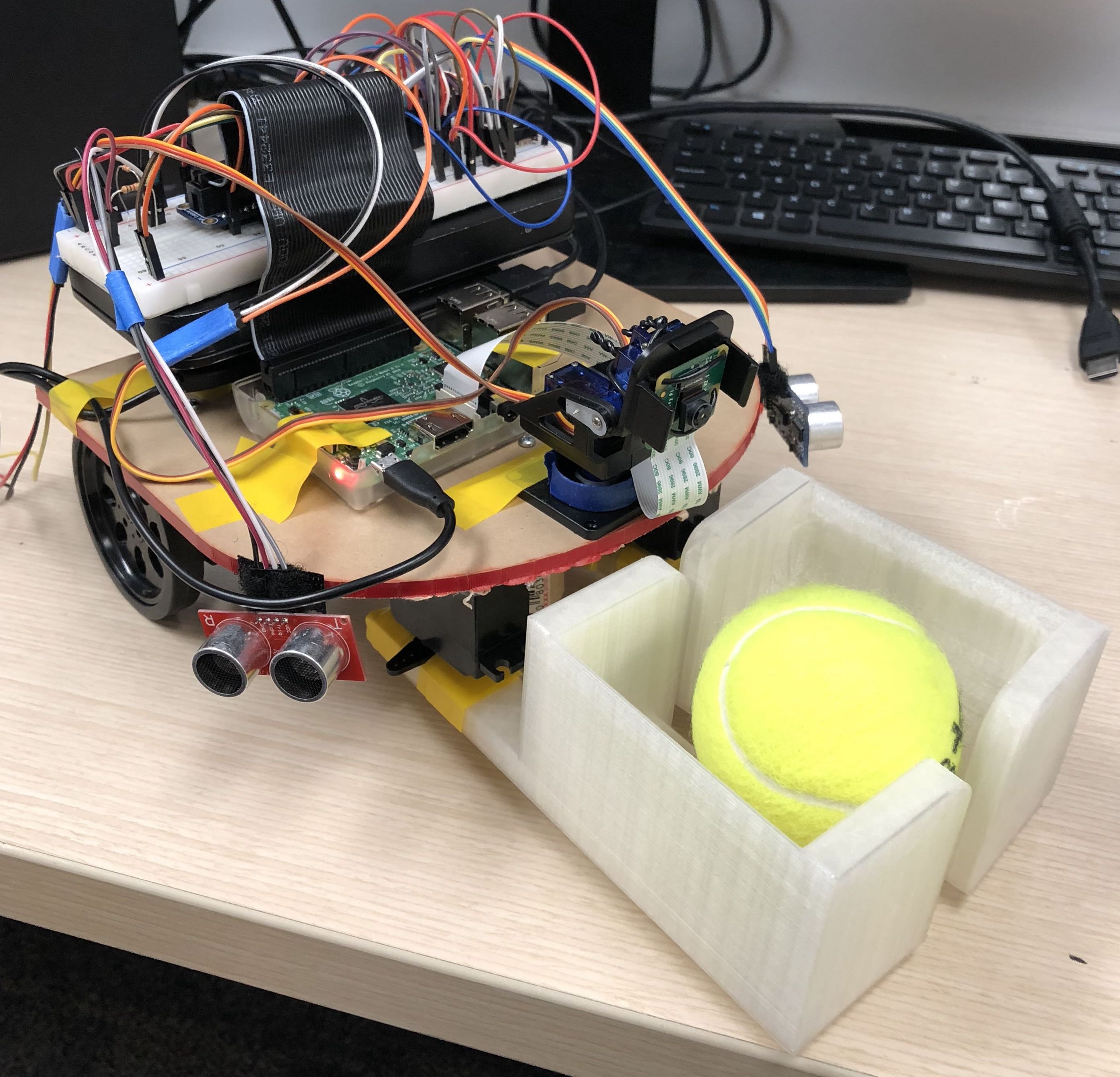
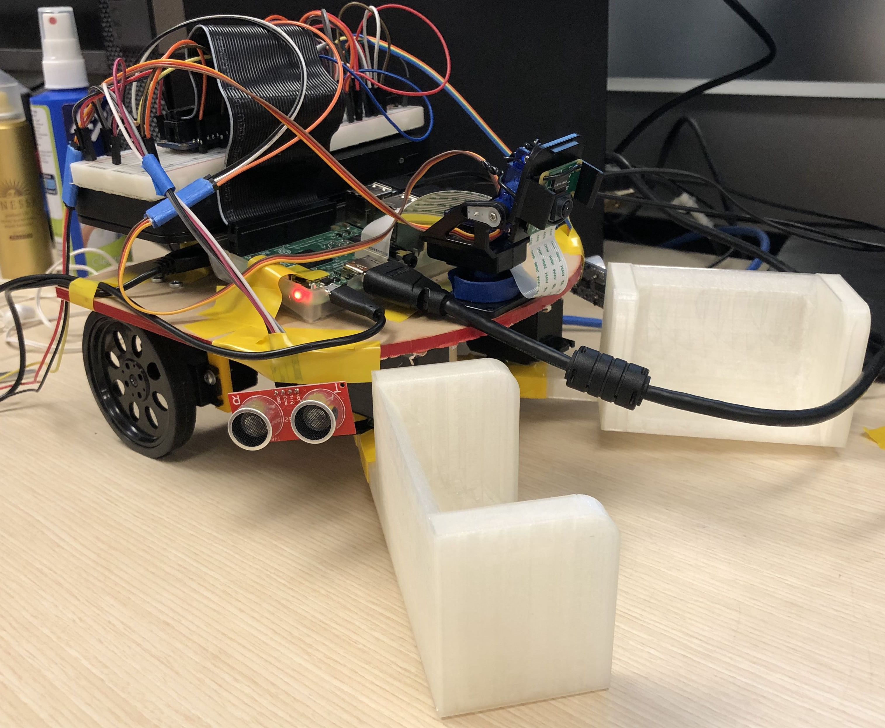
Figure 1. Assembled FetchBot
The robot we designed and built is an autonomous retrieval robot that runs on the Raspberry Pi ver. 3B (RPi) which integrates image processing software with GPIO I/O regulation. The robot was programed to retrieve a green tennis ball and deliver it to the marked drop off location. The initial foundation of this robot concept was based off of the robot developed in Lab 3 in ECE 5725: Design with Embedded Operating Systems.
The RPi served as the brain for the entire system which controlled all the other components on the robot. The hardware for this project included two continuous servo motors that were used for the wheels and two continuous servo motors that were used for the arms. Two 3D printed mechanical arms were used for the retrieval of the target tennis ball. One standard servo was used to operate the camera gimbal at the front of the robot which served to adjust the camera module based on different situations. The camera module used for this robot was the PiCamera Module V2 which allowed for easy integration with the RPi. The collision detection system utilized two ultrasonic sensors, HC-SR04, that detected approximate distance to the closest object.
The entire system was programmed and developed in Python 3.5. By developing our robot in Python on a RPi, we were able to take advantage of the wide variety of packages available to integrate the robot software into one platform that did not require any higher level OS or lower level microcontrollers. The primary packages that served as the foundation for this project are OpenCV and RPi.GPIO. The OpenCV was used to operate the camera module and perform all of the image processing tasks required to detect the green tennis ball object as well as the drop off location marker. The OpenCV package is an all inclusive package that allows for a wide variety of different types of image processing techniques to be utilized. The RPi.GPIO package in Python was used control the I/O ports on the RPi so that communication can be established between the hardware (e.g. servo motors, ping sensors) and the software.
Design and Testing
The overall design and testing for this project was divided into four phases. The image processing and camera module design/testing phase, the mechanical arm retrieval design/testing phase, the collision detection design/testing phase, and the integration and overall system assembly/testing phase. By dividing up the development and design of this robot into four separate phases, we would be able to verify that each component and system was working properly before moving onto the next section.
Image Processing Design
The object detection system utilized several different packages in Python with a PiCamera module that was integrated through the RPi. Inside of our software, the camera module served to capture a “frame” every iteration of the overall while-loop, perform image processing on this single frame, and then retrieve the location of the tennis ball in reference to the screen dimensions. This location data is then passed along to the next phase of the software to determine how the robot should move next.
Inside the infinite while-loop, the image processing algorithm first reads in a frame extracted from the camera module. This frame then serves as the image that the algorithm will work in this iteration. The frame is then converted into the HSV color space so that a ‘mask’ can be created that extracts only the target colored objects from the image. This can be seen this portion of code below.
frame = vs.read()
frame = imutils.resize(frame, width=600)
hsv = cv2.cvtColor(frame, cv2.COLOR_BGR2HSV)
mask = cv2.inRange(hsv, GcolorLower, GcolorUpper)
The mask is created through the cv2.inRange function that extracts only the pixels that are within the ‘upper’ and ‘lower’ range. During the initial object detection phase since we will be trying to retrieve a green tennis ball, we chose the bounds to represent a green object . These specific values are GcolorLower = (29, 86, 6), GcolorUpper = (64, 255, 255). In phase two, once we pick up the tennis ball, we switch our object color detection to yellow, these specific values are YcolorLower = (20, 100, 100), YcolorUpper = (30, 255, 255). This will detect a yellow circular object (e.g. yellow tape roll) instead of a green circular object.
Once the frame has been preprocessed, we then perform erosion and dilation on the mask frame in order to remove general noise. It is important to note that performing more iterations of erosion and dilation will remove more noise, but it will also ‘damage’ the target object in the frame, which may reduce detection sensitive. Next, the software then finds the contours inside of the remaining mask frame. If any contours are found in the object, the software then utilizes cv2.minEnclosingCircle() function to extract that circles x and y position and its estimated radius. Using moments we can then find an approximate center for the ‘object’. This can seen in the code below.
c = max(cnts, key=cv2.contourArea)
((x, y), radius) = cv2.minEnclosingCircle(c)
M = cv2.moments(c)
center = (int(M["m10"] / M["m00"]), int(M["m01"] / M["m00"]))
The software then checks if the radius is larger than a certain value (we chose 2 for our final demo) to help filter out small circles (noise). If the detected circular object is indeed larger, then we determine that the green tennis ball has been found. The software then proceeds into the next phase where our servo motors that control our wheel respond depending on the location of the object in the frame. We can see from the image below that by testing our object recognition algorithm, the software successfully detects the correct object without any issues.
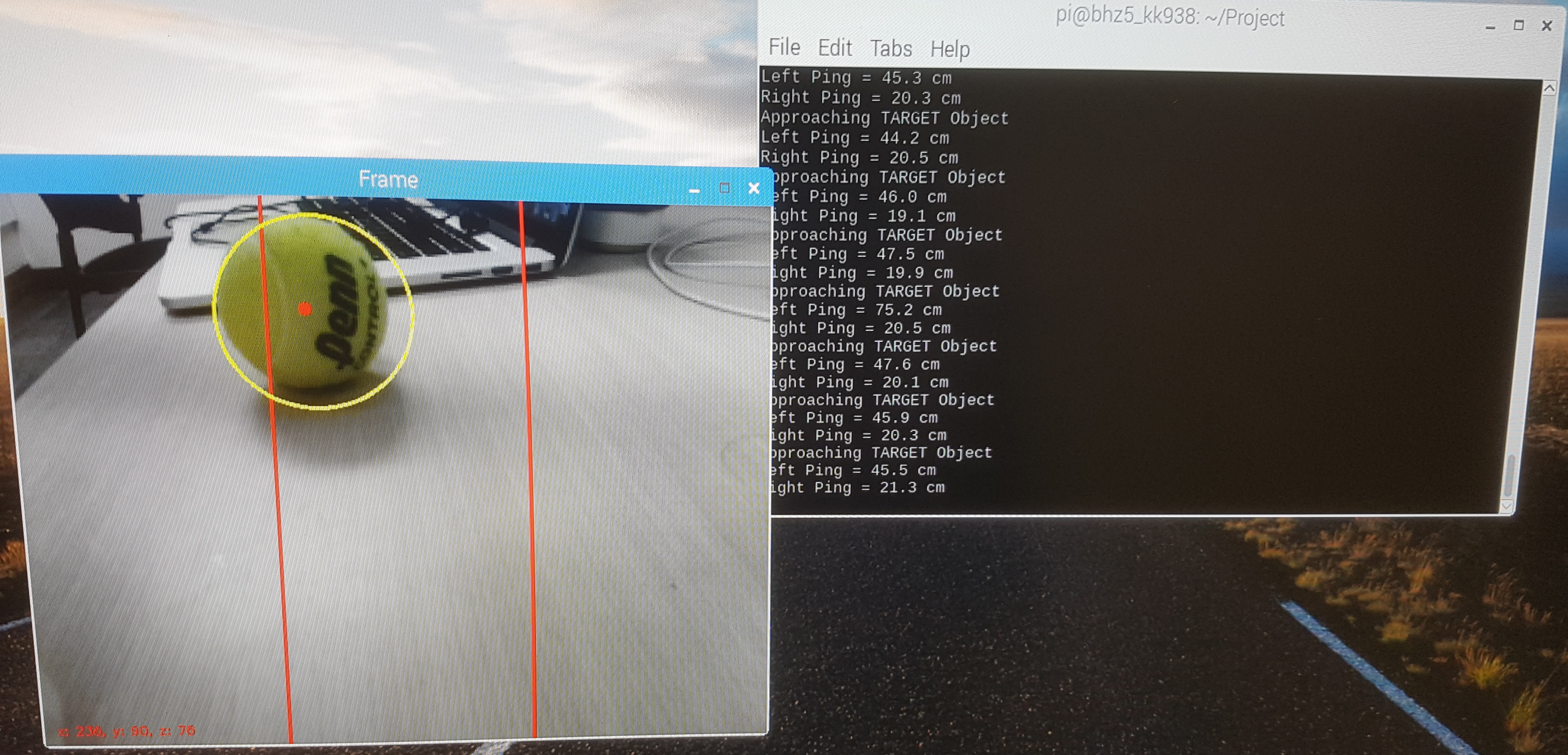
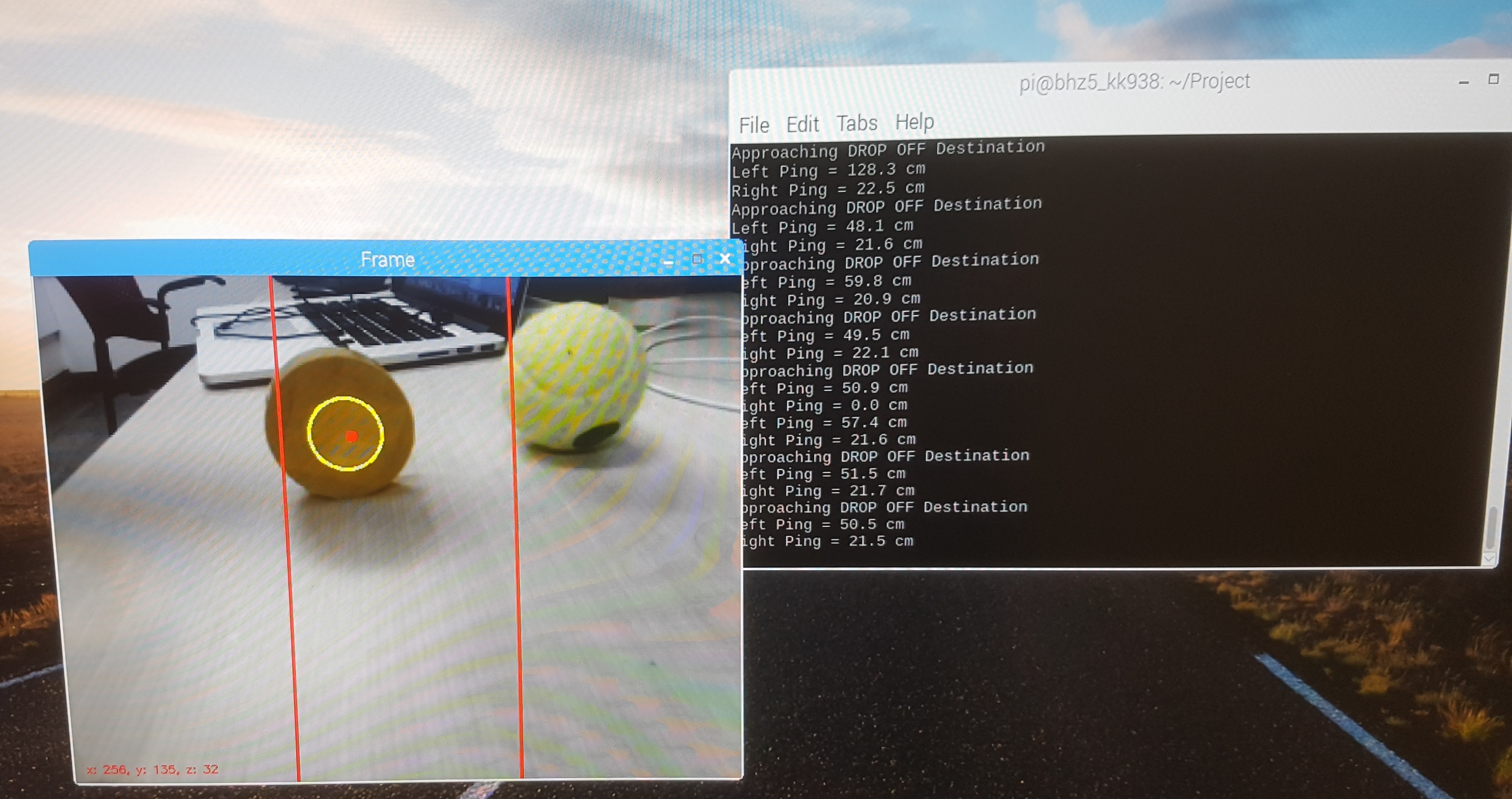
Figure 2. Object Detection Algorithm on Tennis Ball and Tape
Retrieval System Design
The robot grabs and releases the target object using two mechanical arms. The arms were created on a CAD software and were made large enough so that it can scoop up a tennis ball. The CAD files were 3D printed from the Rapid Prototyping Lab (RPL). By having relatively large arms compared to the size of the actual robot, the arms ended up being dragged on the floor. We solved this issue by adding height to the pivot and lifting the whole front area of the robot.
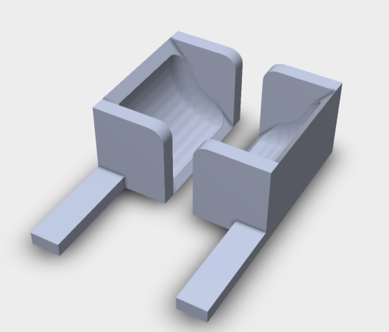
Figure 3. CAD Design of Retrieval Arms
The arms were connected to two continuous parallax servos just like the wheels. The two servo motors were connected to GPIO pins 26 and 20 with fixed frequency of 46.511Hz. Software PWM was used to control the two motors as they do not require a great deal of precision. The servo motors were connected to a separate 5V power source from 4 AA batteries placed underneath the FetchBot and ground was shared with the RPi.
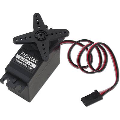
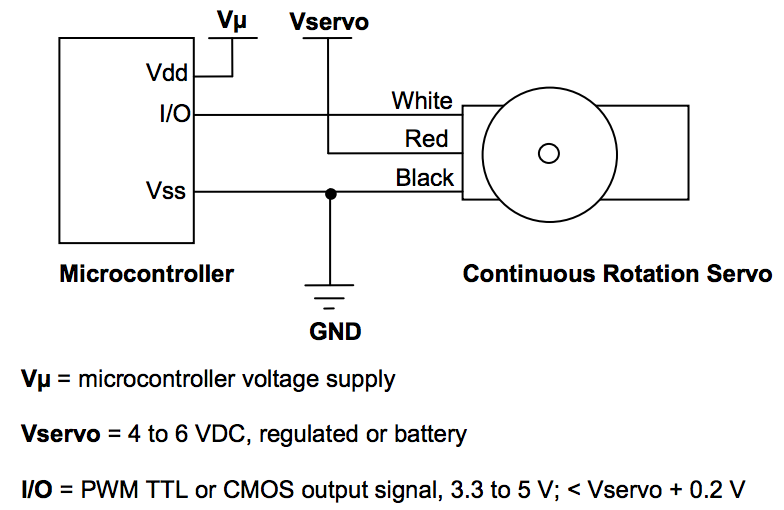
Figure 4. Parallax Continuous Servo Motors
A simple mechanism was implemented to retrieve the ball. We set the two arm motors off until the robot was directly in front of the object. Then we activated the two motors for a short fixed amount of time just enough to close the two arms. After grabbing the object, the servos would turn off again until the drop-off point was reached. Lastly, the motors would be reactivated, run in the opposite direction for a brief moment to release the object.
Collision Detection Design
To avoid our robot from colliding with other objects or walls, we used two ping sensors (HRC-SR04) on the front-left, front-right corner of the robot. The ping sensors are connected to the RPi through the GPIO pins and are continuously polling to see if any object is close by. The ping sensor continuously outputs distance measurements in centimeters and we created a threshold value of 16cm, where the robot will steer away from once there is a reading of 16cm or under. These sensors are relatively accurate to about ~10cm, below which it will become inaccurate.
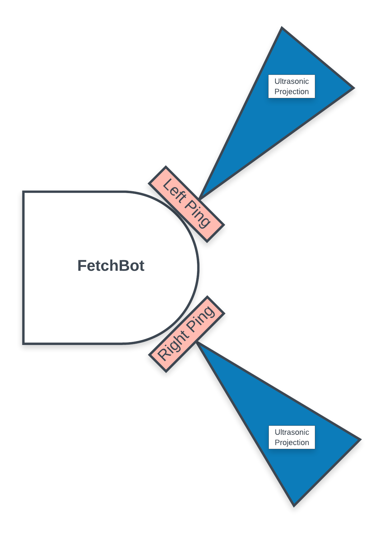
Figure 5. Collision System Design
The ping sensors require 4 pins, VCC, TRIG, ECHO, and GND. VCC was connected to 3.3V supply from the RPi and GND was connected to RPi ground. The two ECHO pins were connected to GPIO #5 and #6 and the TRIG pins of both sensors were connected to GPIO #19. Since the code read the measurements from the ping sensors in series, the TRIG pins were able to be shared.
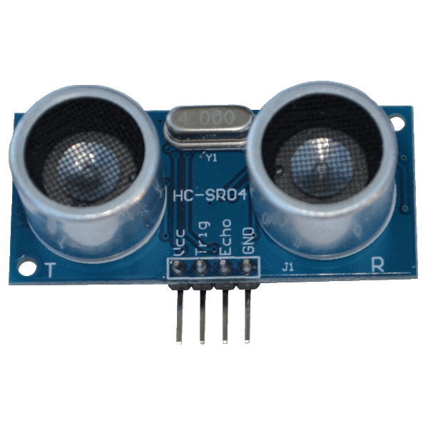
Figure 6. HC-SR04 Ultrasonic Sensors
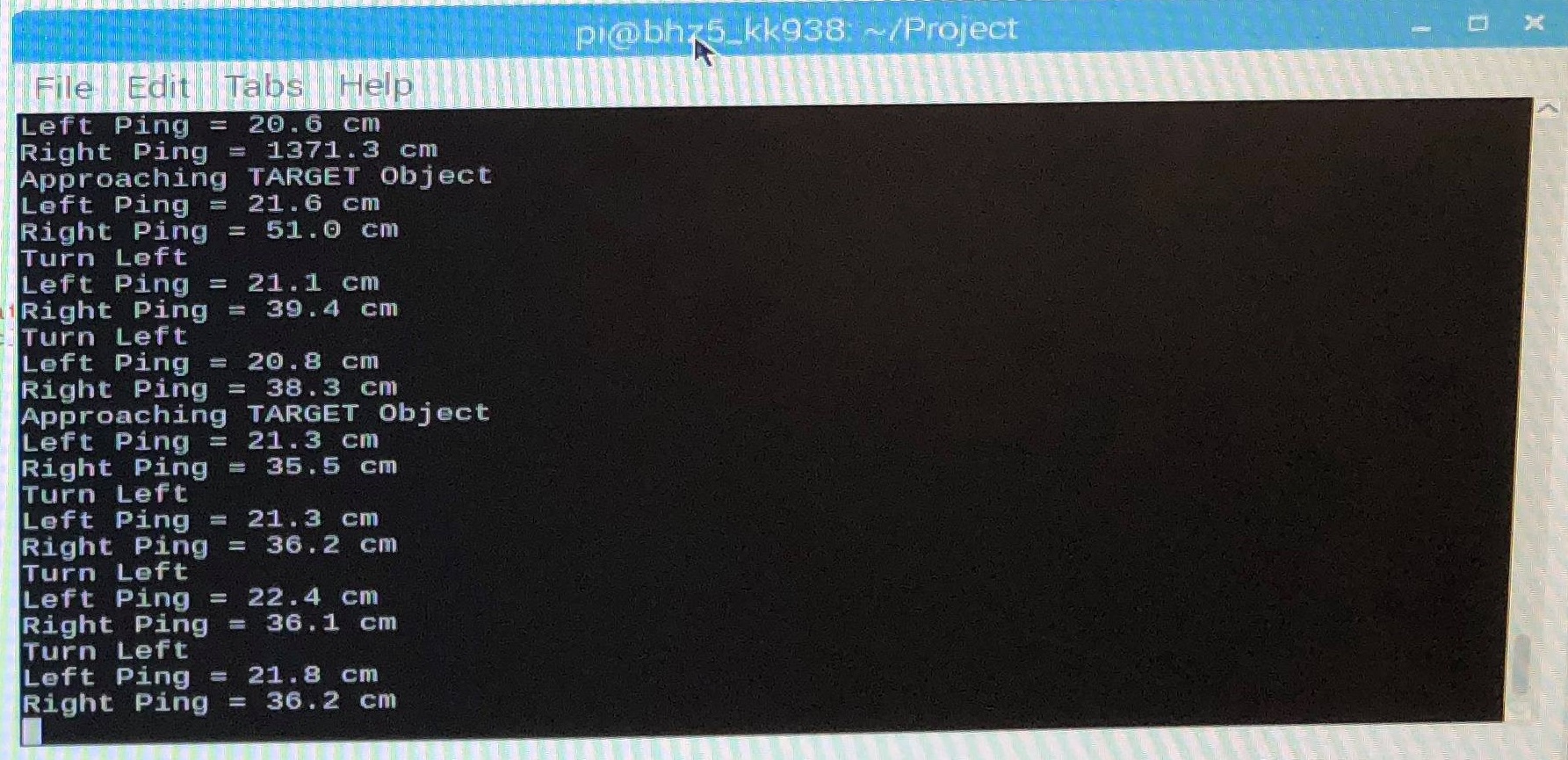
Figure 7. Ultrasonic Sensor Readings
When the left ping sensor goes off, we steer right to avoid collision. When the right ping sensor goes off, we steer left. We also wanted the ping sensors to have higher priority than object detection since the robot can search for the object on its own. Therefore, when the ping sensors detect a close object, we forced a turn left or right for a fixed amount of time and disregarded all the frame reads from the camera.
Overall System Integration
The overall operation of the FetchBot works first by searching for the target object by turning right, moving forward, and turning left in order for a fixed amount of time. When the target object is detected, the robot tries to move left or right to position itself directly towards the object. When the object is aligned with the robot’s direction, the robot starts to move forward. The robot continuously corrects its course of movement to go directly towards the object until it reaches the object. All of these operations take place while the robot is continuously monitoring the distance measurements from the ping sensors. If the ping sensors detect something close, the robot will steer away first, and then search and align itself towards the object.
As the target object gets closer and closer, the robot loses sight of the object because it lies below the viewing angle of the camera. So after the robot gets close enough, the camera tilts down using a standard servo controlled gimbal so that the FetchBot can get a better view of the object. Then, the robot moves closer to the object until a certain threshold value is met so that the robot can grab the object.
The robot pauses its movement and activates its arms to grab the target object. Once the target object is obtained, the camera moves back up so that the robot can search for its drop-off point. The robot searches for the drop-off point in the same manner as it looked for the target object. After the FetchBot reaches its drop-off point, it drops off the object and moves back for a short amount of time.
The overall hardware wiring schematic for the entire system can be seen below. The wiring integrates two continuous servos that control the two wheels, two continuous servos that control the two arms, one standard servo that controls the camera gimbal, and two ultrasonic sensors all with the RPi.
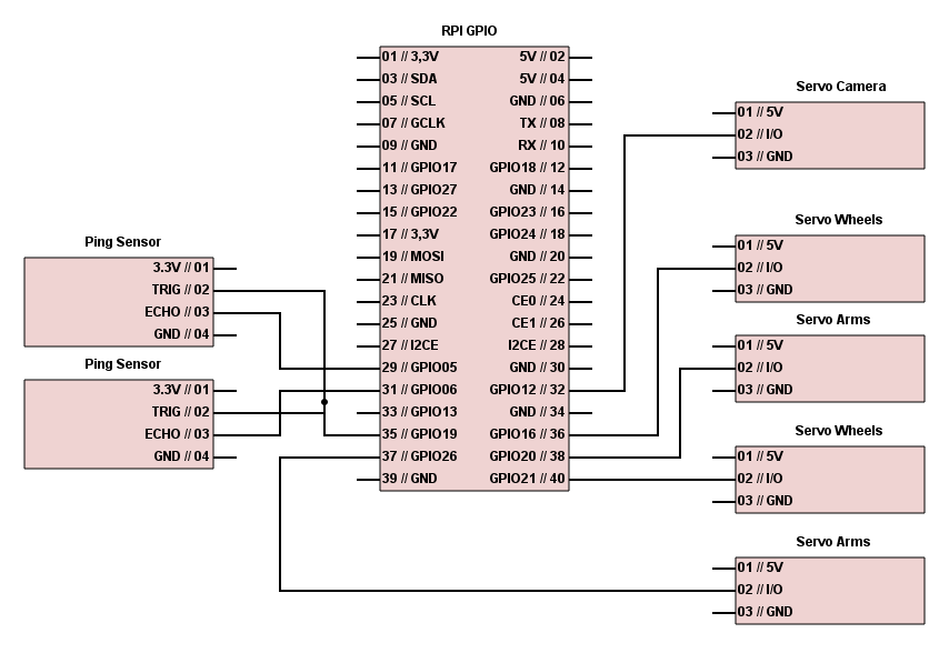
Figure 8. Schematic of Overall System GPIO I/O Pins
Results
Our robot performed as planned and met the goals we expected. It performed perfectly in controlled environments with good lighting, no dark or black objects, and no other objects similar to a tennis ball. In a well defined environment, there was almost no noise and the FetchBot successfully fetched the target object without colliding into walls. The robot was able to distinguish the tennis ball from the yellow tape that we used as our drop-off point.
The robot took a relatively long time to find the target object when the object was too far for the image processing algorithm to capture. In this case the robot blindly moved around (turn right, move forward, turn left) until the object came into view. Still, the robot was able to track down the target object and deliver the ball to the drop-off point eventually.
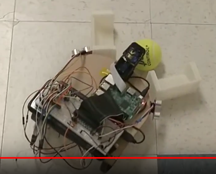
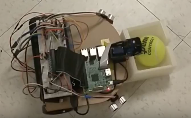
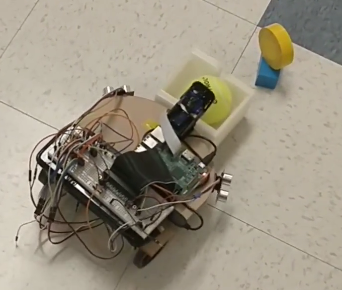
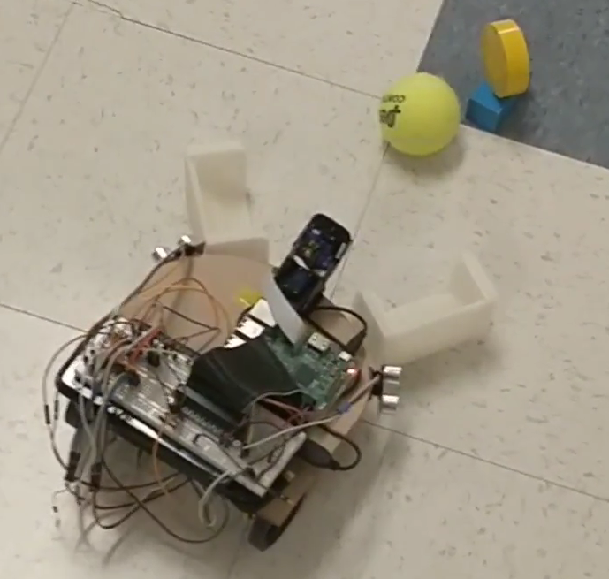
Figure 9. FetchBot Demonstration
FetchBot Video Demonstration
Conclusion
The overall final design, development, and demonstration was a success for our FetchBot. The robot was able to navigate in an open environment and detect the initial tennis ball target, approach it, and retrieve it successfully. The robot was then able to deliver the tennis ball back to the marked drop off location without any issues. We were able to successfully implement a circular colored object detection algorithm based in OpenCV with the RPi in order to detect both the target pick up object as well the final drop off marker. The robot is able to search indefinitely until the target object is found. The robot is able to detect objects up to 2 meters away without any issues. FetchBot also integrates two ultrasonic proximity sensors into the front sides in order to avoid collision with walls and other objects. FetchBot integrates these two ultrasonic sensors with its camera module and object tracking algorithm to successfully create a robust retriever robot that is able perform its task fully autonomously.
During the initial design and testing phase where we tested the object tracking and ultrasonic sensor systems, there were no issues and everything worked as expected. However, during the overall system assembly and testing phase, several problems started to arise once we tried to put the system together. The first issue was that the object tracking algorithm picked up a large amount of noise in the real world environment (e.g. ECE5725 Lab) such as false object detections. In order to solve this problem we utilized the camera gimbal to tilt the camera down towards the ground, thus reducing its field of view but decreasing noise. We combined this with more erosion and dilation filtering on a software image processing level in order to further reduce noise, this again decreases the detection sensitivity of the system but greatly reduces noise detection. The second issue was that the motors would sometimes suddenly stop moving even though the code was still running correctly. This issue took a tremendous amount of time to debug, however, eventually we were able to fix it once we realized that the speed of our program was looping too slow. Initially, we used a rising/falling edge method to read ultrasonic sensor values, this slowed down the program significantly. We eventually switched to a polling method that timeouts after a certain amount of time, speeding up the loop cycling and thus preventing the motors from freezing up. The third issue we ran into involved reading incorrect ultrasonic sensor values. We eventually solved this issue by testing out other sensors and realizing that one of our ultrasonic sensors was dead. In conclusion, we were able to eventually solve all of our issues and successfully integrated our entire robot system to perform its tennis ball retrieval function.
Future Work
The are several different possible future improvements that we foresee would greatly improve the functionality of this FetchBot. The ultrasonic distance sensors on this robot can be replaced with much more accurate, reliable, and efficient infrared proximity sensors to better suit the collision detection system. In future iterations of this robot, we can also increase the number of proximity sensors around the robot so that it has less ‘blind spots’, e.g directly in front of the robot and directly behind the robot.
In future iterations of the image detection software, a better balance can be achieved between object detection and noise filtering. This can be done by doing some trial and error testing with different erosion and dilation cycles while also adjusting the camera angle on the gimbal to achieve the best balance. The current PiCamera V2 module could also be swapped for a more suitable camera that is more suited for actual object detection. For example, a focused fish lens camera can be utilized to increase its horizontal viewing area while increase the ‘depth’ of viewing as well thus increasing the effectiveness of the object detection algorithm tremendously.
The retrieval system of the robot can also be improved by modifying the 3D printed arm design to fit different object types that an individual wants to retrieve as well as increase the carrying capacity of robot. The retrieval system can also be integrated with additional servos enabling it to be able to lift the payload off the ground directly, this would also help increase the carrying capacity of the retrieval system.
Appendix
Code
# Authors: Bryan H. Zhao (bhz5), Jun Ko (kk938)
# ECE 5725 Final Project: FetchBot
# FetchBot_tennisball.py
# Date: 05/16/2018
# Autonomous robot that retrieves a tennis ball and then delivers it to a marked location.

# Import packages here.
import cv2
import time
import RPi.GPIO as GPIO
from imutils.video import VideoStream
import imutils
import sys
import pigpio

def distance_left():
	new_reading = False
	counter = 0
	# set Trigger to HIGH
	GPIO.output(GPIO_TRIGGER, True)

	# set Trigger after 0.01ms to LOW
	time.sleep(0.00001)
	GPIO.output(GPIO_TRIGGER, False)

	StartTime = time.time()
	StopTime = time.time()

	# save StartTime
	while GPIO.input(GPIO_ECHO) == 0:
		pass
		counter += 1
		if counter == 5000:
			new_reading = True
			break
	StartTime = time.time()

	if new_reading:
		return False

	# save time of arrival
	while GPIO.input(GPIO_ECHO) == 1:
		pass
	StopTime = time.time()

	# time difference between start and arrival
	TimeElapsed = StopTime - StartTime
	# multiply with the sonic speed (34300 cm/s)
	# and divide by 2, because there and back
	distance = (TimeElapsed * 34300) / 2

	return distance

def distance_right():
	new_reading = False
	counter = 0
	# set Trigger to HIGH
	GPIO.output(GPIO_TRIGGER2, True)

	# set Trigger after 0.01ms to LOW
	time.sleep(0.00001)
	GPIO.output(GPIO_TRIGGER2, False)

	StartTime2 = time.time()
	StopTime2 = time.time()

	# save StartTime
	while GPIO.input(GPIO_ECHO2) == 0:
		pass
		counter += 1
		if counter == 5000:
			new_reading = True
			break
	StartTime2 = time.time()

	if new_reading:
		return False

	# save time of arrival
	while GPIO.input(GPIO_ECHO2) == 1:
		pass
	StopTime2 = time.time()

	# time difference between start and arrival
	TimeElapsed2 = StopTime2 - StartTime2
	# multiply with the sonic speed (34300 cm/s)
	# and divide by 2, because there and back
	distanceblue = (TimeElapsed2 * 34300) / 2

	return distanceblue

def servo_speed(number, direction):

	global p1
	global p2

	if (number == 1):

		if (direction == 'Clkwise'): # Turn servo 1 clockwise.

			on = 1.45
			off = 20
			p1.ChangeFrequency(1000/(on + off))
			p1.ChangeDutyCycle(on/(on + off)*100)

		elif (direction == 'Counter-Clk'): # Turn servo 1 counter clockwise.

			on = 1.55
			off = 20

			p1.ChangeFrequency(1000/(on + off))
			p1.ChangeDutyCycle(on/(on + off)*100)

		elif (direction == 'Stop'): # Stop servo 1 motion.

			p1.ChangeDutyCycle(0)

	elif (number == 2):

		if (direction == 'Clkwise'): # Turn servo 2 clockwise.

			on = 1.45
			off = 20
			p2.ChangeFrequency(1000/(on + off))
			p2.ChangeDutyCycle(on/(on + off)*100)

		elif (direction == 'Counter-Clk'): # Turn servo 2 counter clockwise.

			on = 1.55
			off = 20
			p2.ChangeFrequency(1000/(on + off))
			p2.ChangeDutyCycle(on/(on + off)*100)

		elif (direction == 'Stop'): # Stop servo 2 motion.

			p2.ChangeDutyCycle(0)

	return

def pick_up():

	global pArmLeft
	global pArmRight

	# Control the two servos for the two mechanical arms to "close" simultaneously to pick up the object.

	on = 1.55
	off = 20
	pArmLeft.ChangeFrequency(1000/(on + off))
	pArmLeft.ChangeDutyCycle(on/(on + off)*100)


	on2 = 1.44
	off2 = 20
	pArmRight.ChangeFrequency(1000/(on2 + off2))
	pArmRight.ChangeDutyCycle(on2/(on2 + off2)*100)

	time.sleep(0.7)

	pArmLeft.ChangeDutyCycle(0)
	pArmRight.ChangeDutyCycle(0)

	return

def drop_off():

	global pArmLeft
	global pArmRight

	# Control the two servos for the two mechanical arms to "open" simultaneously to drop off the object.

	on = 1.4
	off = 20
	pArmLeft.ChangeFrequency(1000/(on + off))
	pArmLeft.ChangeDutyCycle(on/(on + off)*100)

	on2 = 1.6
	off2 = 20
	pArmRight.ChangeFrequency(1000/(on2 + off2))
	pArmRight.ChangeDutyCycle(on2/(on2 + off2)*100)

	time.sleep(0.1)

	pArmLeft.ChangeDutyCycle(0)
	pArmRight.ChangeDutyCycle(0)

	return

# Start the PiCamera module and instantiate it as vs.
vs = VideoStream(usePiCamera=1).start()

#GPIO Mode (BOARD / BCM)
GPIO.setmode(GPIO.BCM)

# GPIO Pins for 2 ping sensors.
GPIO_TRIGGER = 19
GPIO_ECHO = 6

GPIO_TRIGGER2 = 19
GPIO_ECHO2 = 5

GPIO.setup(GPIO_TRIGGER, GPIO.OUT)
GPIO.setup(GPIO_ECHO, GPIO.IN)

GPIO.setup(GPIO_TRIGGER2, GPIO.OUT)
GPIO.setup(GPIO_ECHO2, GPIO.IN)

# GPIO Pins for 2 WHEEL motors.
GPIO.setup(16, GPIO.OUT)
GPIO.setup(21, GPIO.OUT)

p1 = GPIO.PWM(16, 46.511)
p2 = GPIO.PWM(21, 46.511)

# Hardware GPIO setup for camera gimbal.
pi_hw = pigpio.pi()
pi_hw.hardware_PWM(12, 50, 76000)
time.sleep(1)
pi_hw.hardware_PWM(12, 50, 0)
time.sleep(0.1)

time.sleep(1)

p1.start(0)
p2.start(0)

# GPIO Pins for 2 ARM motors.
GPIO.setup(26, GPIO.OUT)
GPIO.setup(20, GPIO.OUT)

pArmLeft = GPIO.PWM(26, 46.511)
pArmRight = GPIO.PWM(20, 46.511)

time.sleep(1)

pArmLeft.start(0)
pArmRight.start(0)

#Establish lower and upper boundaries for green (tennis ball) and yellwo (drop off location) in the HSV color space.

GcolorLower = (29, 86, 6) # For Green
GcolorUpper = (64, 255, 255)

YcolorLower = (20, 100, 100) # For Yellow
YcolorUpper = (30, 255, 255)

# Set up different flag variables to indicate different phases and situations in the enviornment.

counter = 0

search_time_current = 0

destination_holdtime_current = 0

phase_2_flag = 0

look_down = 0

search_LeftRight = "R"

while True:

	# PING sensor distance calculations

	left_dist = distance_left()
	print ("Left Ping = %.1f cm" % left_dist)
	time.sleep(0.02)

	right_dist = distance_right()
	print ("Right Ping = %.1f cm" % right_dist)
	time.sleep(0.2)

	# Servo motors will prioritize turning away from objects (either left or right) base on each ping sensor reading.
	if (left_dist <= 16) or (right_dist <= 16):

		# About to collide
		servo_speed(1, 'Stop')
		servo_speed(2, 'Stop')

		if (left_dist <= 16) and (right_dist <= 16):

			# Wall in front.
			# Turn 180 degrees
			servo_speed(1, 'Counter-Clk')
			servo_speed(2, 'Counter-Clk')
			continue

		elif (left_dist <= 16):

			# Turn Right
			servo_speed(1, 'Counter-Clk')
			servo_speed(2, 'Counter-Clk')
			search_LeftRight = "R"

			continue

		elif (right_dist <= 16):

			# Turn Left
			servo_speed(1, 'Clkwise')
			servo_speed(2, 'Clkwise')
			search_LeftRight = "L"

			continue

	# Read the current frame from the camera module.
	frame = vs.read()

	# Resize the frame, blur it, and convert it to the HSV color space.
	frame = imutils.resize(frame, width=600)

	hsv = cv2.cvtColor(frame, cv2.COLOR_BGR2HSV)

	# Construct a mask for "green" and "yellow" based on either the pick up phase or the drop off phase.
	if (phase_2_flag == 0):

		mask = cv2.inRange(hsv, GcolorLower, GcolorUpper)

	if (phase_2_flag == 1):

		mask = cv2.inRange(hsv, YcolorLower, YcolorUpper)

	# Perform a series of dilations and erosions to remove any small blobs/noise left in the mask.
	# Higher iterations will remove more noise but reduce object detection senitivity.
	mask = cv2.erode(mask, None, iterations=4)
	mask = cv2.dilate(mask, None, iterations=4)

	#Find contours in the mask and initialize the current (x, y) center of the ball.
	cnts = cv2.findContours(mask.copy(), cv2.RETR_EXTERNAL,
		cv2.CHAIN_APPROX_SIMPLE)[-2]
	center = None

	# Draw two reference lines on the image to indicate where the system will turn left, right, or go straight.
	cv2.line(frame, (200,0), (200,450), (0, 0, 255), 2)
	cv2.line(frame, (400,0), (400,450), (0, 0, 255), 2)

	#Proceed only if at least one contour was found
	if len(cnts) > 0:

		# Find the largest contour in the mask, then use it to compute the minimum enclosing circle and centroid.
		c = max(cnts, key=cv2.contourArea)
		((x, y), radius) = cv2.minEnclosingCircle(c)

		# Utilizing moments, the center of mass of any object can be estimated.
		M = cv2.moments(c)
		center = (int(M["m10"] / M["m00"]), int(M["m01"] / M["m00"]))

		# Proceed only if the radius meets a minimum size.

		if radius > 2:

			# OBJECT IS FOUND.

			cv2.circle(frame, (int(x), int(y)), int(radius),
				(0, 255, 255), 2)
			cv2.circle(frame, center, 5, (0, 0, 255), -1)

			# calculate the int radius, int x, int y
			rad = int(round(radius))
			xAxis = int(round(x))
			yAxis = int(round(y))

			# If target object is close, turn the camera angle down to adjust for close range field of view.
			if ( rad >= 120 ) and (look_down == 0) and (phase_2_flag == 0):

				servo_speed(1, 'Stop')
				servo_speed(2, 'Stop')

				pi_hw.hardware_PWM(12, 50, 87500) # 50Hz, 8.75% duty cycle
				time.sleep(1)

				pi_hw.hardware_PWM(12, 50, 0)
				time.sleep(0.1)

				look_down = 1

				continue

			# If target object gets farther away, turn the camera angle back up to adjust for far range field of view.
			if ( rad < 100 ) and (look_down == 1) and (phase_2_flag == 0):

				servo_speed(1, 'Stop')
				servo_speed(2, 'Stop')

				pi_hw.hardware_PWM(12, 50, 76000)
				time.sleep(1)

				pi_hw.hardware_PWM(12, 50, 0)
				time.sleep(0.1)

				look_down = 0

				continue

			###########################################################################################################################
			# Approaching the target tennis ball.

			if (xAxis > 200) and (xAxis < 400) and (rad >= 190) and (phase_2_flag == 0):

				servo_speed(1, 'Stop')
				servo_speed(2, 'Stop')
				print ("Target Object reached")

				destination_holdtime_start = time.time()
				destination_holdtime_end = time.time()
				destination_holdtime_current = destination_holdtime_current + (destination_holdtime_end - destination_holdtime_start)

				if (destination_holdtime_current > 0.0001):

					destination_holdtime_current = 0

					# PICK UP THE OBJECT.
					pick_up()

					time.sleep(3)

					pi_hw.hardware_PWM(12, 50, 76000)
					time.sleep(1)

					pi_hw.hardware_PWM(12, 50, 0)
					time.sleep(0.1)

					look_down = 0

					phase_2_flag = 1

			elif (xAxis > 200) and (xAxis < 400) and (rad < 190) and (phase_2_flag == 0):

				destination_holdtime_current = 0

				servo_speed(1, 'Counter-Clk')
				servo_speed(2, 'Clkwise')
				print ("Approaching TARGET Object")

			###########################################################################################################################
			# Approaching the target drop off point.

			elif (xAxis > 200) and (xAxis < 400) and (rad >= 95) and (phase_2_flag == 1):

				servo_speed(1, 'Stop')
				servo_speed(2, 'Stop')
				print ("DROP OFF Destination reached")

				destination_holdtime_start = time.time()
				destination_holdtime_end = time.time()
				destination_holdtime_current = destination_holdtime_current + (destination_holdtime_end - destination_holdtime_start)

				if (destination_holdtime_current > 0.0001):

					destination_holdtime_current = 0

					# DROP OFF THE OBJECT.
					drop_off()

					time.sleep(1)

					# Back up a little bit.
					servo_speed(1, 'Clkwise')
					servo_speed(2, 'Counter-Clk')

					time.sleep(2)

					# Clean up and stop all connections.

					p1.stop()
					p2.stop()

					pArmLeft.stop()
					pArmRight.stop()

					pi_hw.stop()

					GPIO.cleanup()
					cv2.destroyAllWindows()
					vs.stop()

					sys.exit()

			elif (xAxis > 200) and (xAxis < 400) and (rad < 95) and (phase_2_flag == 1):

				destination_holdtime_current = 0

				servo_speed(1, 'Counter-Clk')
				servo_speed(2, 'Clkwise')
				print ("Approaching DROP OFF Destination")

			###########################################################################################################################

			elif (xAxis <= 200): # Turn Left

				destination_holdtime_current = 0

				servo_speed(1, 'Stop') #Stop
				servo_speed(2, 'Clkwise')
				print ("Turn Left")

			elif (xAxis >= 400): # Turn Right

				destination_holdtime_current = 0

				servo_speed(1, 'Counter-Clk')
				servo_speed(2, 'Stop') #Stop
				print ("Turn Right")

			# Place direction info on screen
			cv2.putText(frame, "x: {}, y: {}, z: {}".format(xAxis, yAxis, rad),
				(10, frame.shape[0] - 10), cv2.FONT_HERSHEY_SIMPLEX,
				0.35, (0, 0, 255), 1)

	else:

		# SEARCH FOR OBJECT.

		# Rotate in a circle to search for object.

		search_time_start = time.time()
		search_time_end = time.time()
		search_time_current = search_time_current + (search_time_end - search_time_start)

		# Rotate in circle
		if (search_time_current < 0.00015):

			if (search_LeftRight == "R"):

				# Rotate RIGHT to look around robot if ping sensor on left triggered.
				servo_speed(1, 'Counter-Clk')
				servo_speed(2, 'Stop') #Stop
				print ("Searching - Rotating Right")

			if (search_LeftRight == "L"):

				# Rotate LEFT to look around robot if ping sensor on right triggered.
				servo_speed(1, 'Stop') #Stop
				servo_speed(2, 'Clkwise')
				print ("Searching - Rotating Left")

		elif (search_time_current >= 0.00015) and (search_time_current < 0.00025):

			# Move forward a little bit.
			servo_speed(1, 'Counter-Clk')
			servo_speed(2, 'Clkwise')
			print ("Searching - Going Forward")


		elif (search_time_current >= 0.00025):

			search_time_current = 0

	cv2.imshow("Frame", frame)
	key = cv2.waitKey(1) & 0xFF
	counter += 1

	# Break the loop if "q" is pressed.
	if key == ord("q"):

		break

# Clean up and stop all connections.

p1.stop()
p2.stop()

pArmLeft.stop()
pArmRight.stop()

pi_hw.stop()

GPIO.cleanup()
cv2.destroyAllWindows()
vs.stop()
sys.exit()
Bill of Materials
| Parts | Cost/Unit | Units | Total Cost |
|---|---|---|---|
| Raspberry Pi Model 3B | $35 | 1 | $35 (Not Included) |
| PiCamera Module V2 | $25 | 1 | $25 |
| Parallax Continuous Servo Motor | $13 | 4 | $52 |
| Standard Servo Motor | $10 | 1 | $10 |
| Ultrasonic Sesnsors (HC-SR04) | $2 | 2 | $4 |
| 3D Printed Mechanical Arms | $0 | 2 | $0 |
| Robot Frame (e.g. wheels) | $0 | 1 | $0 |
| Battery Pack | $0 | 1 | $0 |
| Total Cost: | $91 |
Member Contributions
The overall work involved the collaboration of both Bryan H. Zhao and Jun Ko. Bryan was mainly responsible for the software development and design portion of this project. He integrated the image processing algorithm with the servo motor controls and set up the communication between the RPi and the hardware components. Jun was mainly responsible for the hardware development and design portion of this project. He wired all the connections for the RPi with all of the other hardware components such as the servo motors, the camera module, and the ping sensors. The final overall system assembly and debugging required the combined efforts of both Bryan and Jun to try and understand if the errors in the system were caused by a software or hardware issue or both.
References
PyImageSearch Tennis Ball Tracking Algorithm ECE 5725 Final Project: FindBot by Alberto Gutiérrez, Boling Hu Ultrasonic Range Sensors (HC-SR04) Python Code Ultrasonic Range Sensors (HC-SR04) Data Sheet Parallax Continuous Rotation Servo Data Sheet
Acknowledgements
We would like to thank Professor Joe Skovira for helping us acquire all the necessary hardware parts, tips to debug issues, and support for successful completion of our project. We would also like to thank the TAs, Brendon and Joyce for helping us out whenever we had questions. Joe has given us many insightful advice on both embedded systems and project design in general. He has created a class where we enjoyed the entire process, from theory in the lectures to hands on application in the labs.