Software
server.py
Aboard the plotter is a Raspberry Pi which runs the Debian Operating System
“Jessie,” a form of embedded Linux. This microcontroller acts as a server which
accepts a connection from the canvas over TCP. The server implements a series of
methods which perform motor controls to move the plotter head. The server runs a
main thread, move_dispatch, which queries a custom queue data structure for motor
movements. This data structure, move_queue, stores delta x and y values as tuples
(dx, dy) which are used to independently move the two stepper motors attached
to the mechanical belt system. In particular, when a new movement is read in from
the move_queue, the next element is popped off the queue and a thread is spawned
which calls upon a stepper_worker to tick each motor in either the forward or
reverse direction for the specified number of deltas.
A second important method, move, is invoked via Remote Procedure Calls (RPC) from
the client device. This method fills the move_queue data structure by dispatching a
thread to push the received delta x and y values to the move_queue as tuples. Based
on the RPC system, the move method must terminate before the client is allowed to
resume execution. Therefore, we found it necessary to dispatch a thread in this
method which would independently push a new tuple to the queue. This permits
the client to resume as quickly as possible while allowing the server to arbitrate
the shared queue resource.
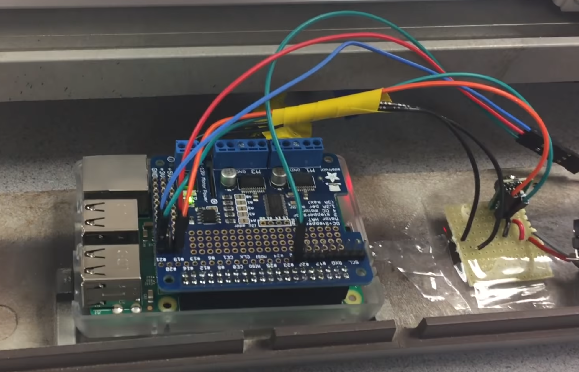 Figure 10: Raspberry Pi with Stepper Motor Hat on Plotter
client.py
The handheld device consists of a second Raspberry Pi which runs a program that reads
in user interaction via a TFT touch-screen. Using the PyGame API, the program displays
a number of buttons on the touch screen and detects particular motions to invoke
appropriate procedures on the server. The Graphical User Interface (GUI) has several
buttons that allow the user to:
- Quit the program and close the server
- Clear the TFT screen of any drawings
- Pause the plotter while it’s in motion and resume the plotter from its position
- Change colors on the touch screen
- Manually move the plotter head up, down, left, or right
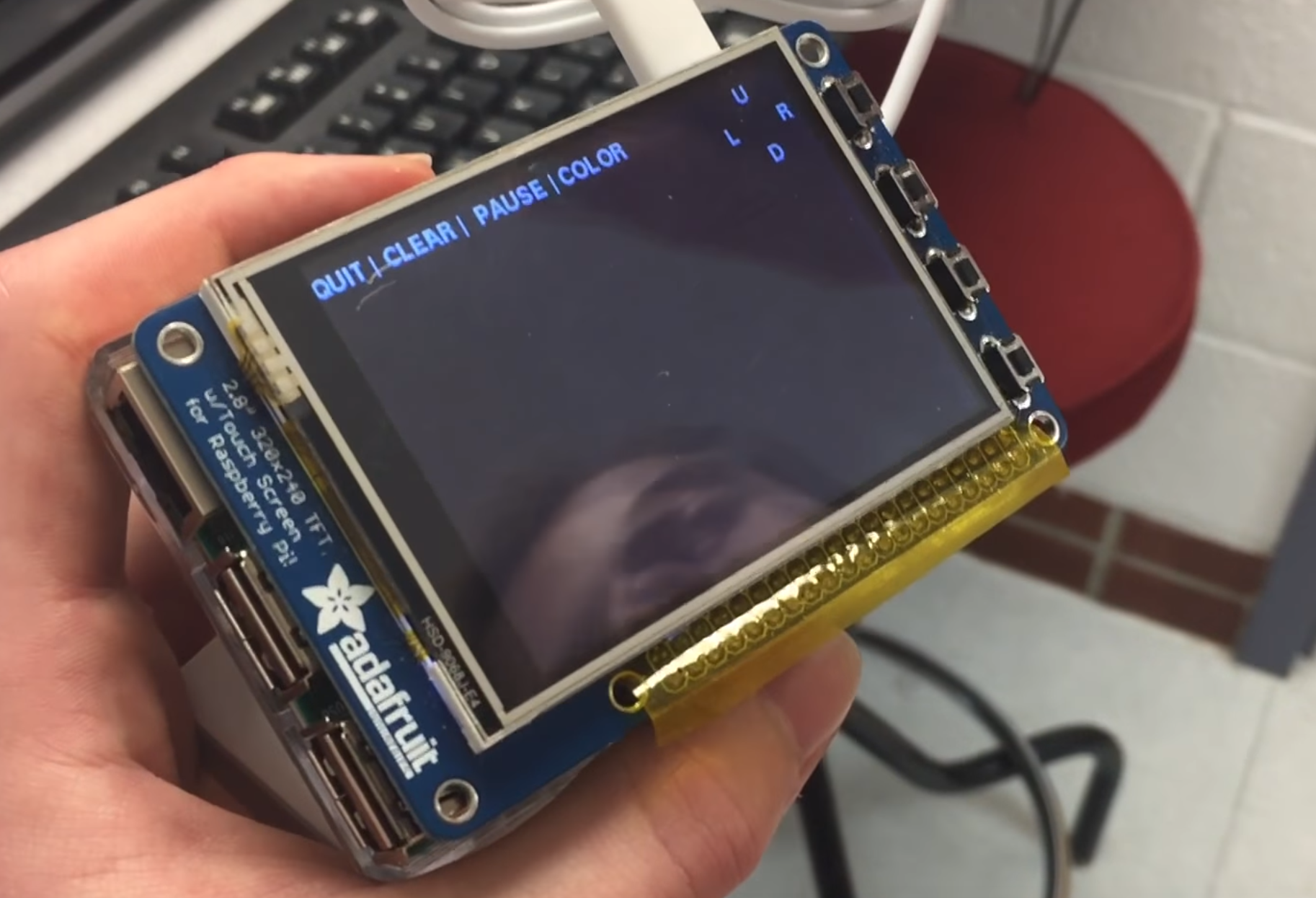 Figure 11: Handheld Raspberry Pi showing controls
The client program runs a main loop which polls for user ‘mouse clicks’ on the screen.
If a single click is detected, we determine that a button on the navbar must be
pressed, so an associated function is executed for each (listed above). In the case
that the user makes a brush stroke movement, the stroke is drawn to the screen and the
program invokes a remote procedure move on the server with the calculated dx and dy
values based on the difference between previous and current mouse positions.
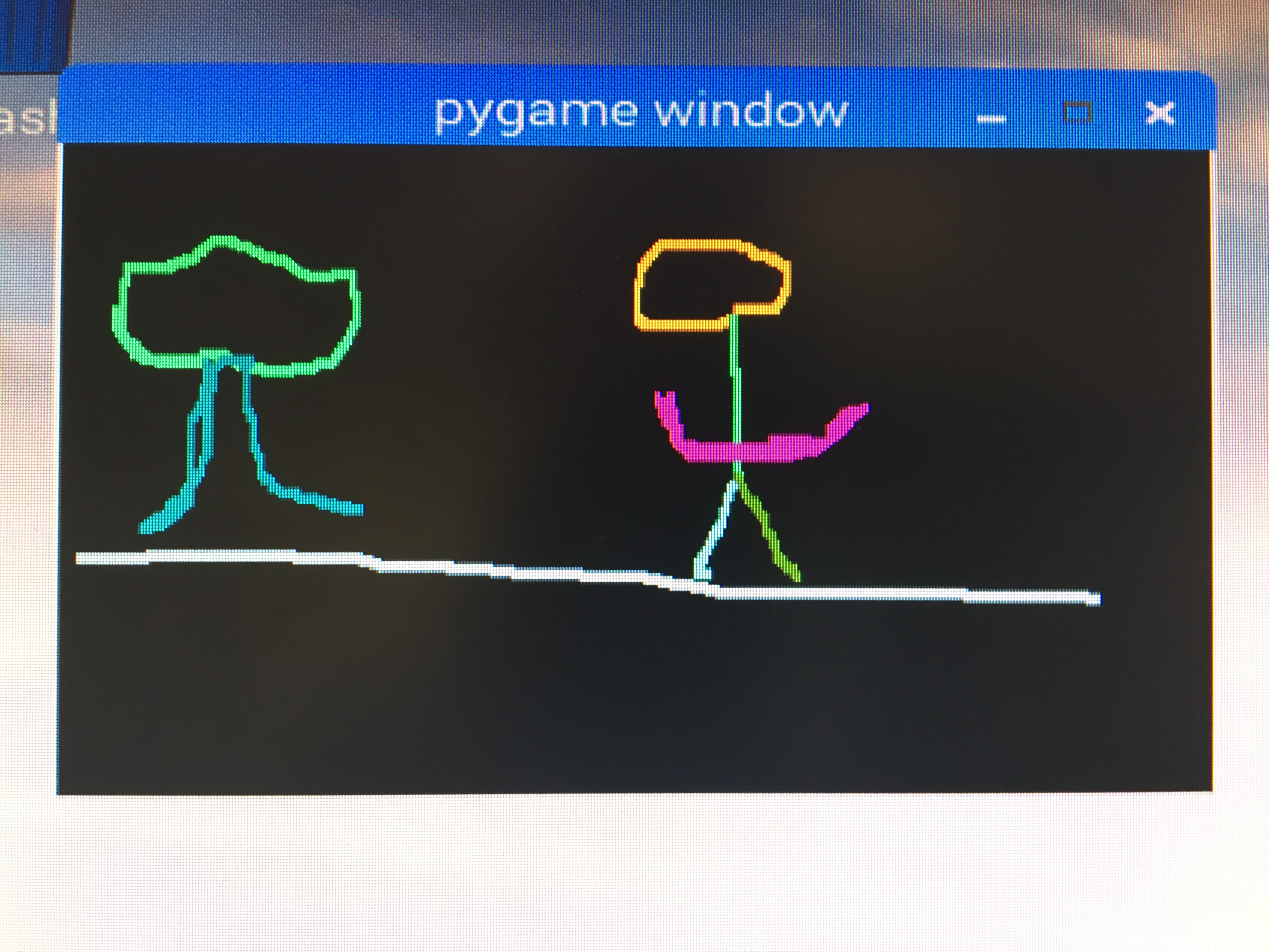 Figure 12: Some random scribbles on test screen
Interprocess Communication: Remote Procedure Calls
The communication protocol operates over TCP between the two host machines. To modularize
and streamline the operation of the motors, we used an API msgpack-rpc. MessagePack is a
communication protocol that uses binary serialization of JSON packets to communicate between
running processes. Through this process, by establishing a TCP connection between the server
and client, we are able to easily invoke processes between hosts without having to build our
own message decoding system. The Python API, msgpack-rpc, allows a user to invoke server-side
methods from the client by simply using the syntax ‘client.call(server_method_name,arg1,arg2,...).’
In our case, we used this communication method to call server method ‘move’ with dx and dy
values for the x and y stepper motors, respectively.
Issues Faced
Plenty of issues arose in both the mechanical construction and software design of this project.
Firstly, since we were working with an old plotter, there were rusty parts that made smooth
movement of the plotter head near impossible. A lot of WD-40 did the trick (somewhat). Secondly,
as far as the mechanical construction goes, the stepper motors we intended to install didn’t fit
the existing frame. We therefore machined custom L-brackets and modified the frame such that it
would fit our components. Lastly, for hardware constraints, it was difficult interfacing with the
on-board solenoid for lifting and placing down the plotter’s pen head. The solenoid had power
requirements that were out of the scope of our design. Given time constraints, we decided to
implement our own external servo for lifting the pen head. However, as fate would have it,
this also proved difficult to implement since the servo would not hold tension on the plotter
head. We eventually scrapped the idea for having control over lifting and placing the plotter
head for the time being.
As for software, there were issues in working to make the plotter operate in real-time given
speed constraints of the stepper motors. Since the user moves quicker than the motors could
operate, it was necessary to build a custom queue data structure to hold user movements such
that these could be executed by the plotter sequentially. Additionally, when trying to dispatch
multiple stepper workers to execute motor operations, there was significant jitter from multiple
threads trying to move the same motor at once. To resolve this, we added a busy-wait in the main
loop of the server which prevents a motor movement from being released on the move_queue until
each motor has completed its previous movement.
Testing Performed
Our first goal was to operate the stepper motors independently of the plotter frame. This involved
interfacing with the motor hat on the server-side alone. Once functions were written which performed
motor movements immediately upon invocation on the server, we worked to incorporate these into the
full system with the client. After making the GUI display to the user, we turned the system such that
the x and y motors would move independently according to the delta values from the user input. Once
the system was fully integrated, we began tuning the motor speeds and mechanical parts such that we
obtained the highest-fidelity image drawn to paper. This involved experimenting with different motor
speeds, scalar sizes, and stepper worker method calls. Once satisfied with the system, it was simply
a matter of setting up the Pis such that each obtained a unique IP address so that they could communicate
over the Cornell network.

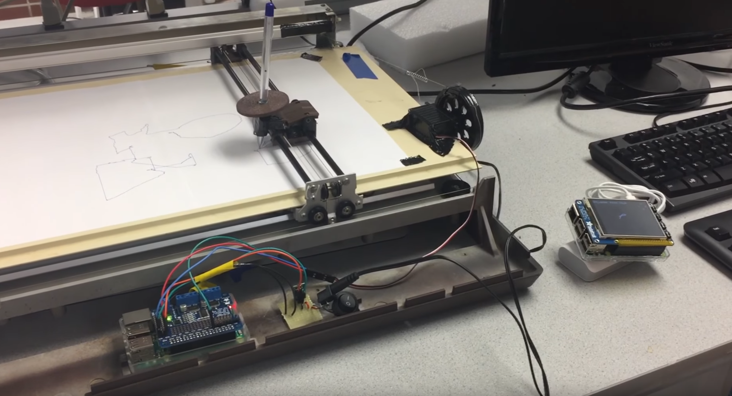 Figure 1: Final Design
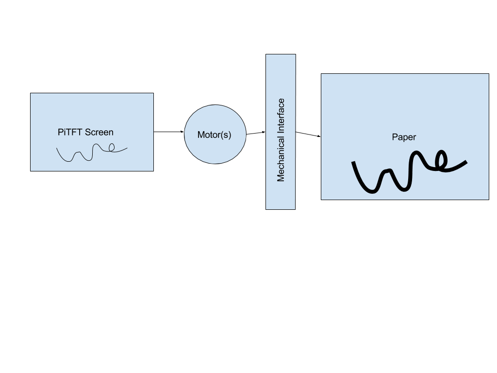 Figure 2: System Diagram
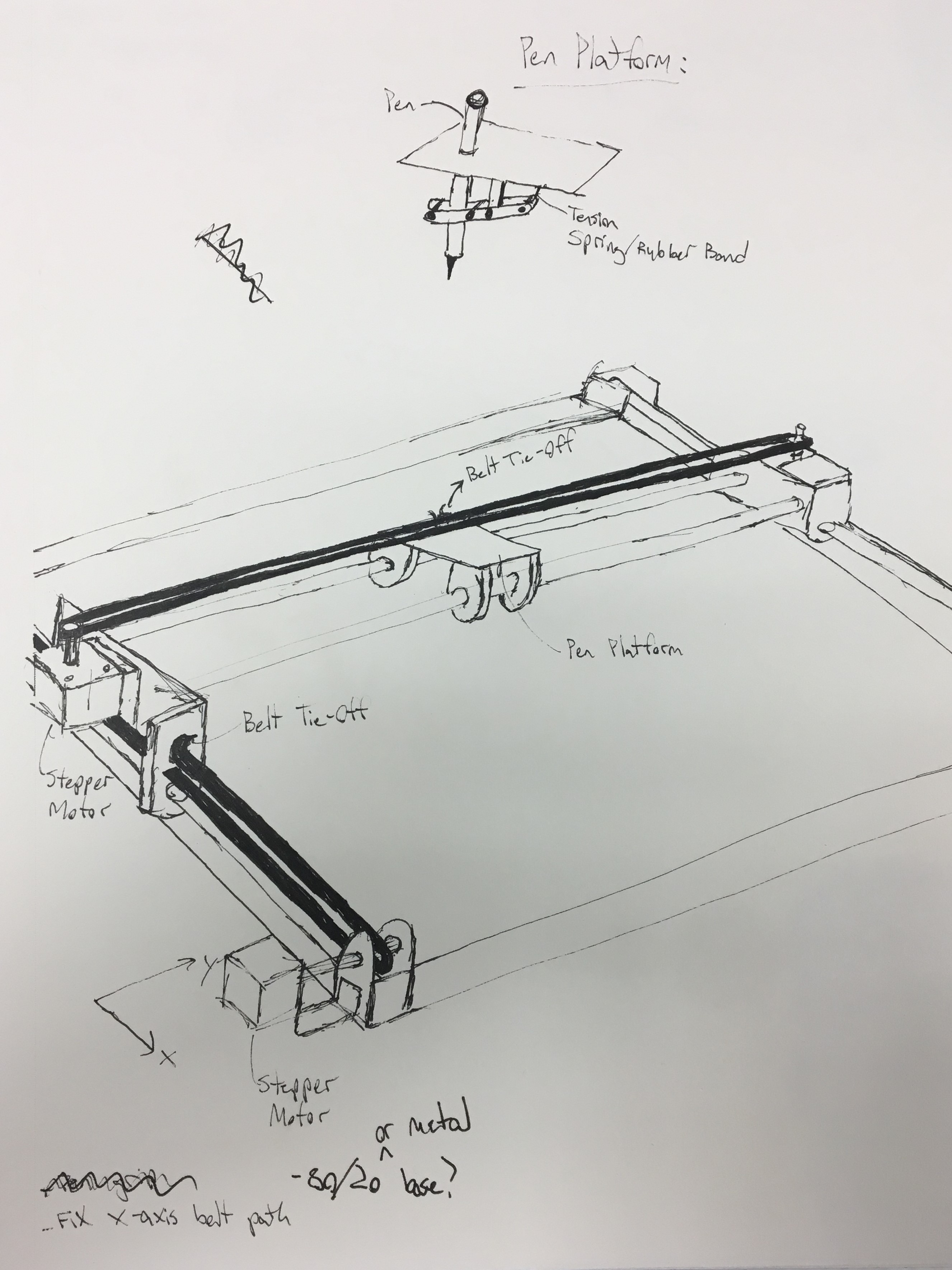 Figure 3: Hardware Design Ideation
We then realized that our system already reflected that of a standard 2D plotter. On search for
a similar device, we came across a plotter generously donated by Prof. Bruce Land.
Figure 3: Hardware Design Ideation
We then realized that our system already reflected that of a standard 2D plotter. On search for
a similar device, we came across a plotter generously donated by Prof. Bruce Land.
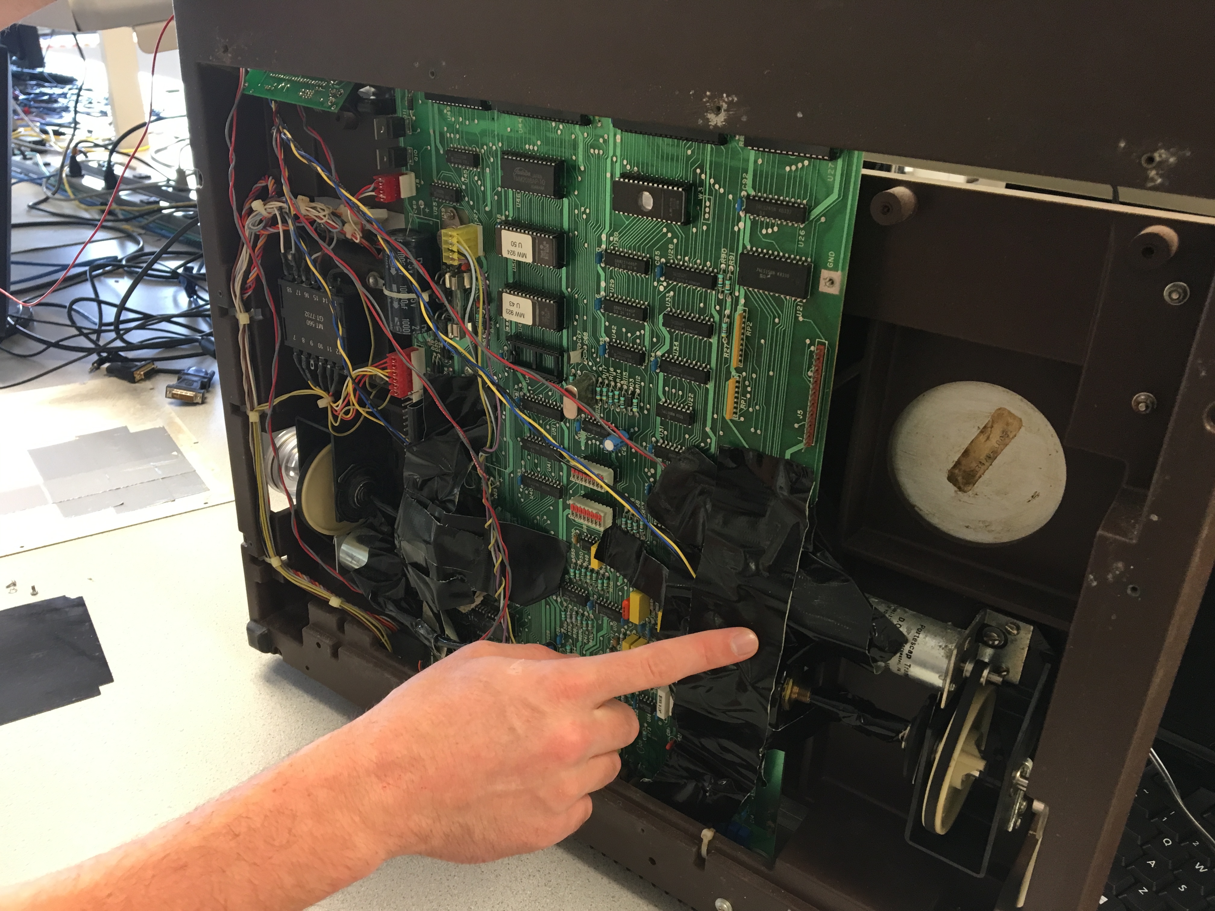 Figure 4: Old plotter before its gutting
The HIPLOT DMP-29 pen plotter undercarriage contained outdated electrical and mechanical components, which were removed.
The original servo motor and drive gearing is highlighted in figure 4.
Figure 4: Old plotter before its gutting
The HIPLOT DMP-29 pen plotter undercarriage contained outdated electrical and mechanical components, which were removed.
The original servo motor and drive gearing is highlighted in figure 4.
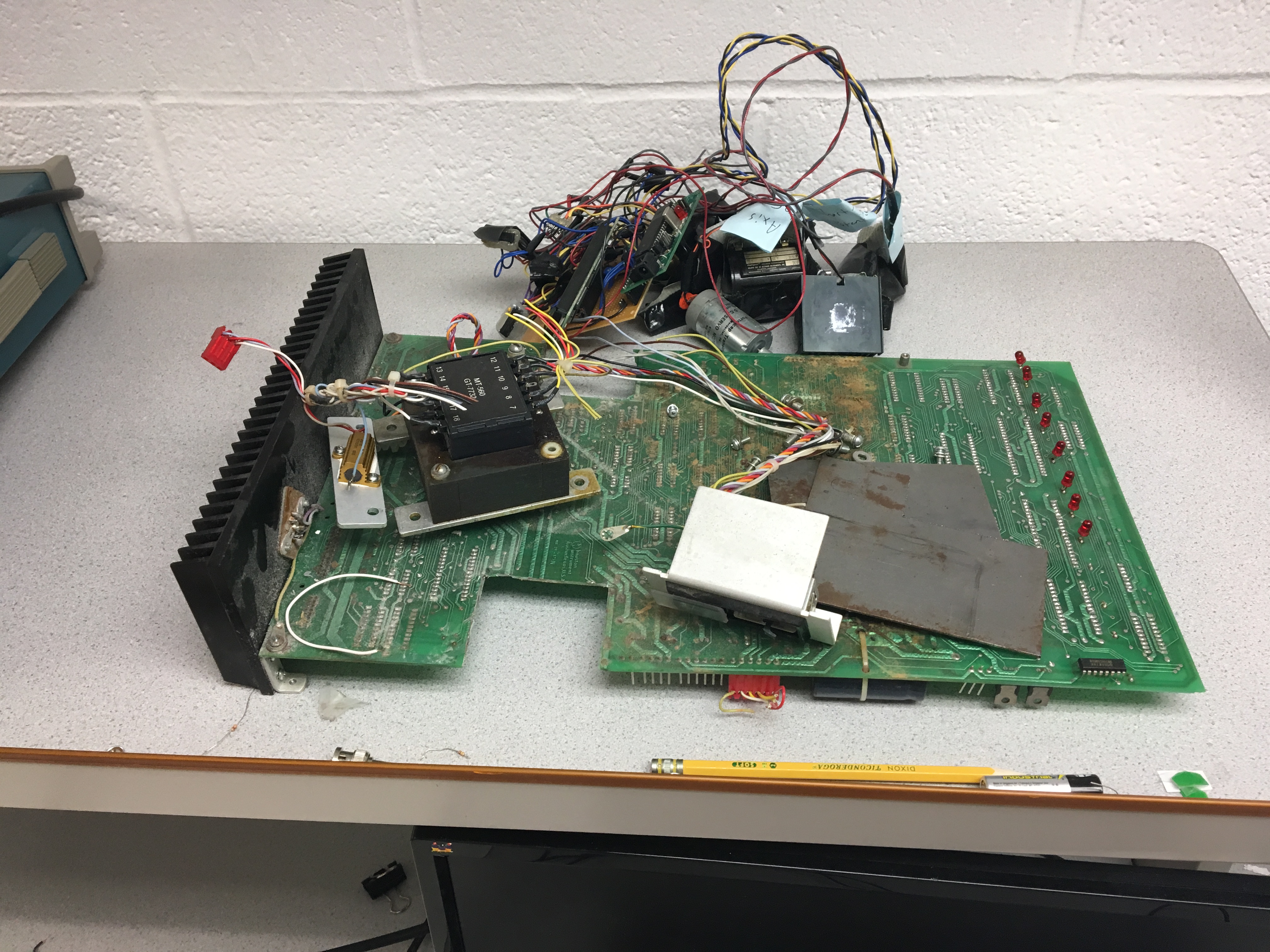 Figure 5: Gutted Components
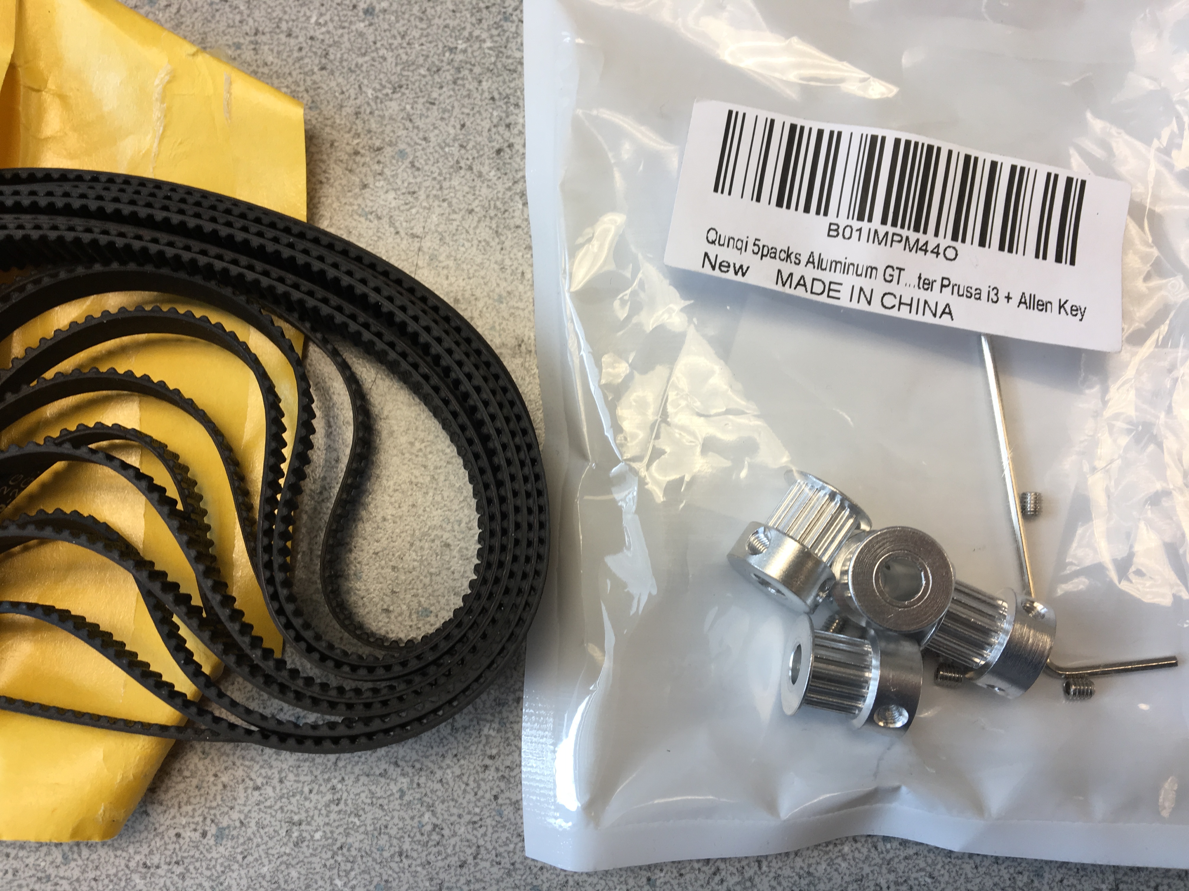 Figure 6: Custom geared belt and pulley components
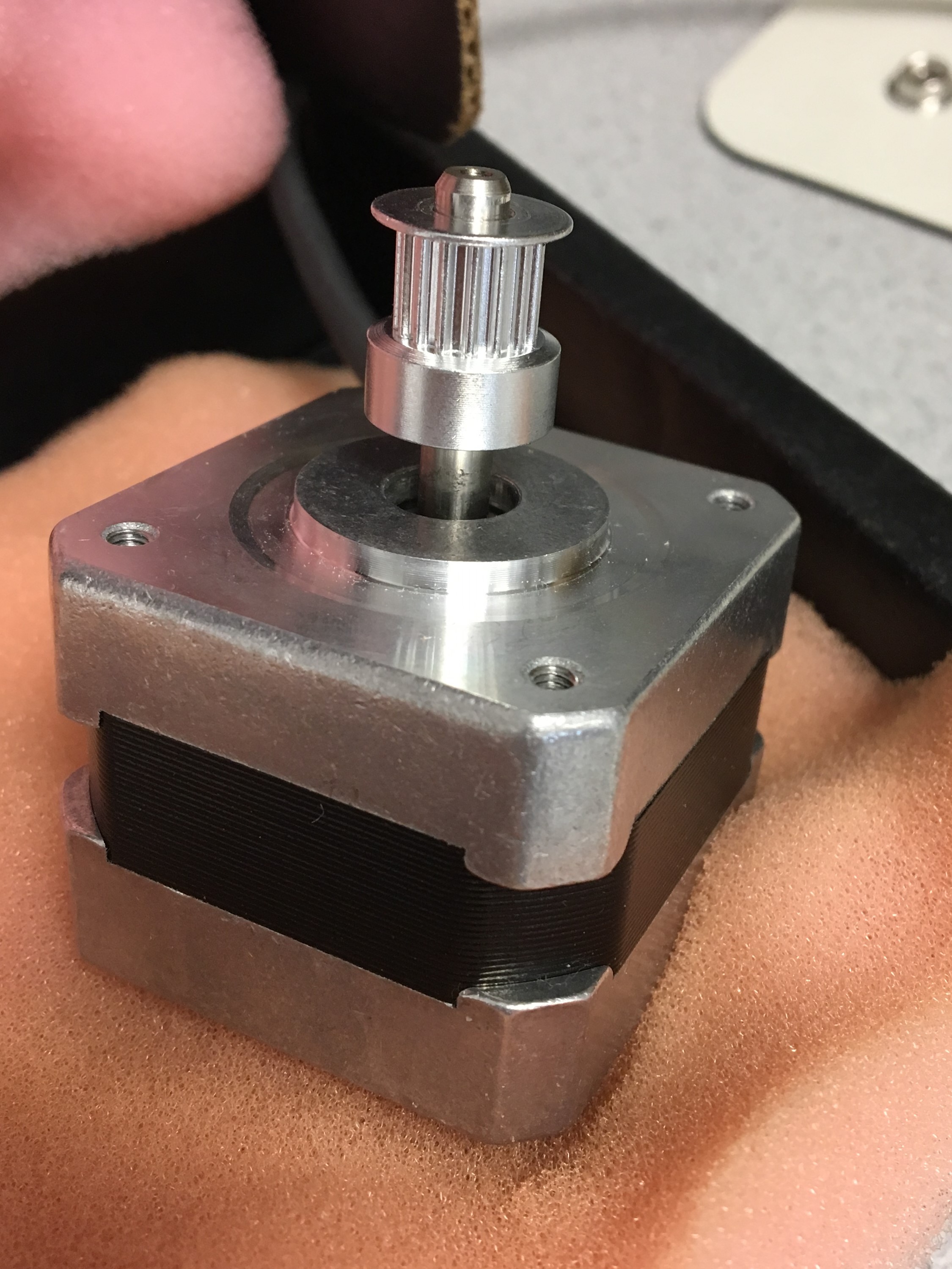 Figure 7: NEMA 17 stepper motor with gear attached
 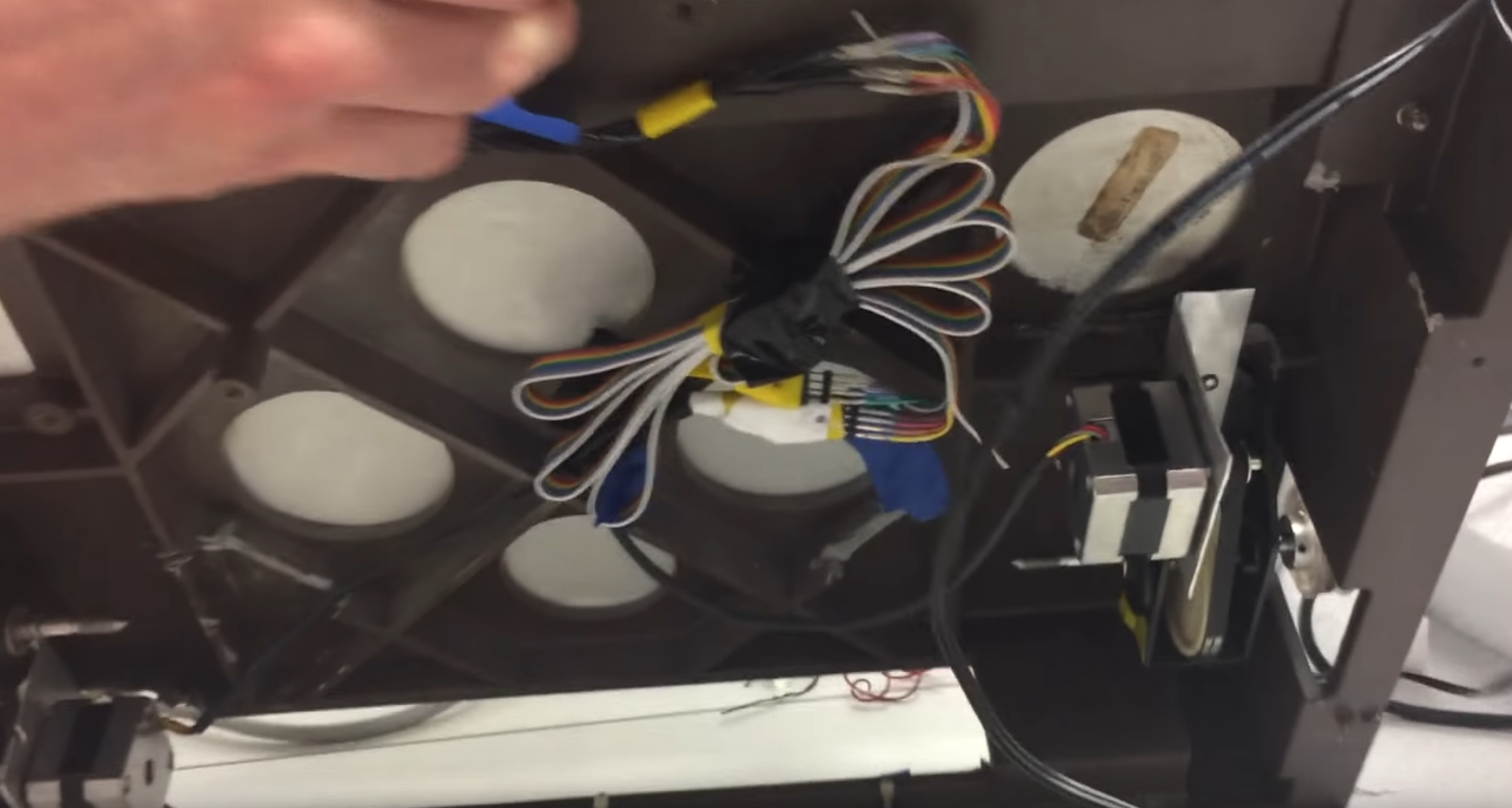 Figure 8: Final gutted undercarriage
 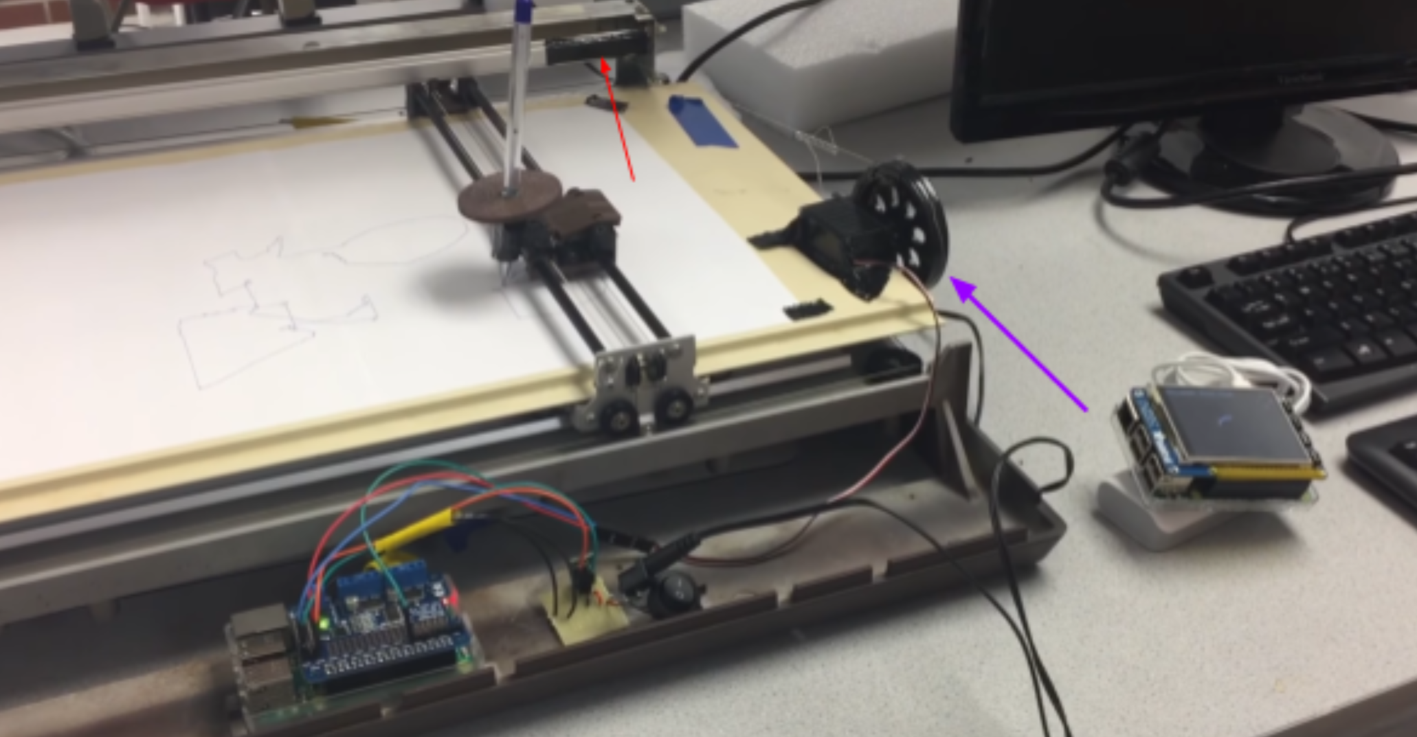 Figure 9: Attempt to install servo
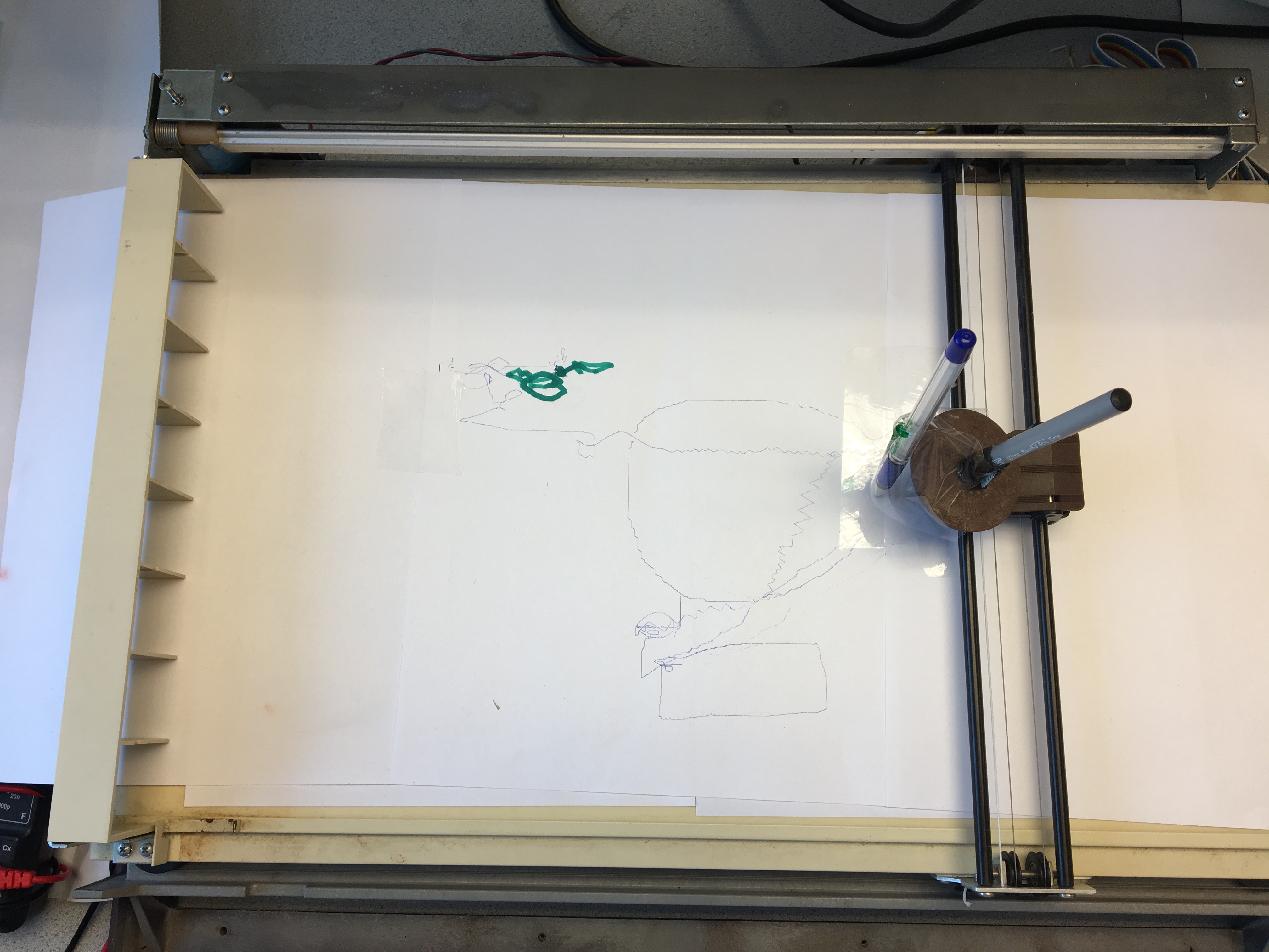 Figure 13: Some random scribbles on plotter