Video-Based Polyphonic Theremin
Video-Controlled Audio Synthesizer
Aaron Logan (apl86) & Shreyas Renganathan (sr2322)
Demonstration Video
Objective
The theremin is an icon of musical experimentation, used in avant-garde movie soundtracks, concertos, and even pop music through the ages. However, we feel its potential for wider use is limited by monophonic-only playback, specialized hardware, and poor configurability of control inputs. The goal of this project was to develop a polyphonic video-based system that preserves the theremin’s distinctive mode of interaction while utilizing polyphonic playback, off-the-shelf hardware, and audio control that is user-mappable to the three orthogonal spatial axes. Using simple cameras, speakers, and a Raspberry Pi, we were able to create a working proof-of-concept, paying homage to the legendary instrument while expanding the toolkit available to the theremin player.
Introduction
The theremin is a monophonic electronic instrument invented in 1920 by Russian physicist Leon Theremin. One plays the theremin by moving their two hands in relation to two fixed antennas, simultaneously controlling voice pitch (one antenna) and volume (other antenna). Our system, the Video-Based Polyphonic Theremin, uses a similar control schema to control a configurable set of audio playback parameters. The system achieves this by: tracking hand positions in 3D space via two video cameras with perpendicular fields of view, passing their Cartesian coordinates as numerical values to an audio synthesizer, and using those values to adjust parameters of a playing audio signal in (soft) realtime.
To enable a richer user experience with the instrument, a graphical user interface (GUI) was added. This provided the ability to map up to four hands to a selectable voice, and the ability to map motion along each orthogonal spatial axis to a selectable audio parameter, out of three choices: pitch, volume, and cutoff frequency of a low-pass filter.
Design and Testing
An early choice in this project was to pursue a modular design, to allow for development and validation of the various subsystems in parallel. Consequently, this project consists of four such subsystems:
We also dedicate a design and testing subsection to:
The overall design scheme uniting these subsystems is shown in Figure 1.

Figure 1. The design and design process of each subsystem is outlined in the following subsections.
Hand Tracking
The video input system was designed for two video cameras, with perpendicular fields of view, feeding into a computer vision algorithm. The algorithm then tracks the player's hands and determines each hand's location along three orthogonal axes. See Figure 2. The actual setup we used is shown in Figure 3.
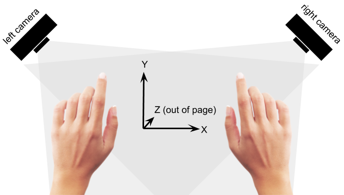
Figure 2. Concept of operation for playing the instrument: two video cameras with perpendicular fields of view track the player’s hands along three orthogonal axes of movement. Each hand controls one synthesizer voice, and movements along each axis modulates one parameter (e.g. pitch) of each voice.
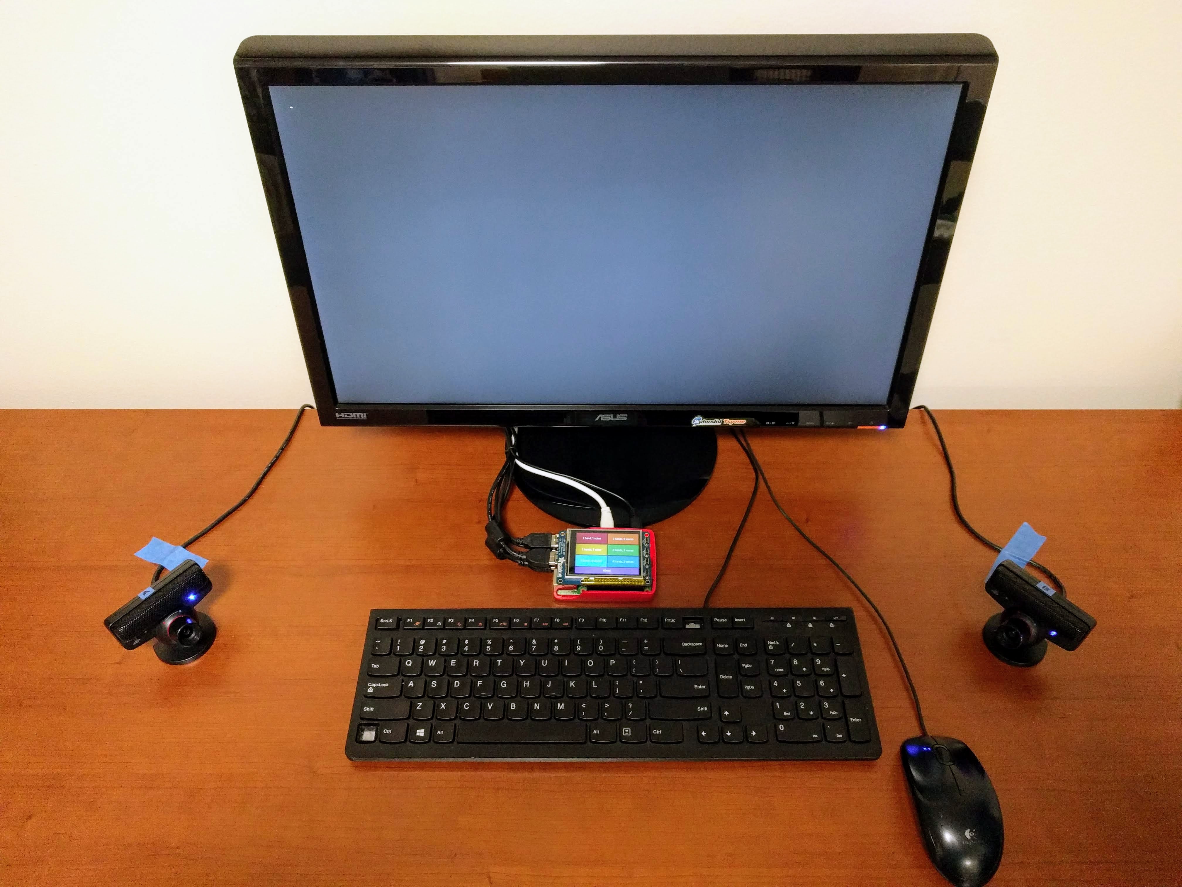
Figure 3. Physical setup we used for testing our theremin. The two PlayStation Eye cameras, on either side of the keyboard, are facing in roughly perpendicular directions, and are canted upwards from the desk in order to center on the space in which instrument play takes place. The Raspberry Pi is just behind the keyboard and is shown displaying (on the PiTFT display) the GUI’s main menu.
This particular arrangement of cameras was chosen so that movements along both the X- and Y-axes would be observed by both cameras. Additionally, having two cameras allows the positions to be averaged between the two video streams; the impact of an anomaly within one of the streams on the averaged measurement is therefore mitigated.
We decided early on to use OpenCV as our platform for video processing, due to Aaron’s prior experience with the software, its proven track record, stability, and power as a software platform, and the preponderance of documentation and usage examples available on the Web. We also decided before commencing with work to use the Python language bindings instead of C++. This would make development far easier and simplify integration with the GUI, which we’d already decided upfront to implement in Python. Although Python executes more slowly than compiled C++ code, the underlying implementation of OpenCV is compiled and therefore runs with the speed of C++.
Installation of OpenCV on the Raspberry Pi was simple once we discovered the right path (or, at least, one that worked for us!). Attempts to follow various installation tutorials online involving piecewise software installations with apt or apt-get resulted in dependency errors. Eventually we realized that installing with pip3 was all that was necessary. Although we didn’t specify a version number, this gave us version 4.1.1. With OpenCV installed in this manner, we initially encountered an error with import cv2 inside Python, wherein a shared object failed to load. A sufficient workaround was to create an alias for python3 in $HOME/.bashrc to first set LD_PRELOAD to the path of the appropriate shared object and then call python3 itself. Later, we realized that, because we were running our theremin program with sudo (for correct operation of PyGame on the PiTFT), cv2 could not be found upon import. This was because we had forgotten to call pip3 with sudo in the original installation, which resulted in the module being installed in the home directory, instead of /usr/local/lib. So we re-installed OpenCV with sudo pip3, and this solved the issue. Interestingly, this installation gave us version 4.4.0, as opposed to 4.1.1 from before.
The next step was to get our feet wet working with video cameras in OpenCV. By this point we had already obtained two PlayStation Eye USB cameras on loan from Professor Skovira. Thankfully, this camera model is one we had already identified pretty early on in our research as being popular for use with OpenCV, so we knew it would work. Initially, we wrote a simple program, live_feed.py, by lifting the video capture and display portions of Amar Prakash Pandey’s code [4] (more on that later), and expanding it to capture from two webcams “simultaneously”. (In actuality, pairs of video frames are grabbed sequentially, but the operation appears simultaneous to a human user.) The code uses the two file system paths of the webcams (needed to open the cameras when creating the video capture objects) and uses those to uniquely identify each camera by superimposing a “1” or “2” on the corresponding live feed.
On that note, we wanted a means by which to reliably identify the two cameras, such that one camera plugged into a particular USB port would always be identified as camera “1”, and likewise for camera “2”, regardless of the order in which they’re plugged in. Initially, we checked to see if the cameras had unique serial numbers that could be seen at system-level. Running lsusb to check devices plugged into the USB ports identified two identically named cameras. Next we queried the udev system by running udevadm info --attribute-walk /dev/bus/usb/001/004 | grep -i -e product -e serial | sort, where the USB bus number (001) and device number (003 or 004) came from running lsusb. The only serial we could find (0000:01:00.0) wasn’t particularly meaningful, and moreover was the same for the two cameras. Our conclusion was that the two cameras look exactly the same to the system and are only distinguishable by the USB port they’re plugged into. So we decided instead to focus on a mapping from USB port to camera number. The Video4Linux system sets up video device paths when cameras are plugged in, in /dev/v4l/. We initially tried setting up a udev rules file in /etc/udev/rules.d/ to add symlinks /dev/usbcam1 and /dev/usbcam2 to the specific device paths pointed to in /dev/v4l/. Unfortunately, this didn’t work: the symlinks were not created as expected. What ended up working was simply to add our own symlinks, locally within our project directory, to the paths under /dev/v4l/ which were clearly mapped to specific USB ports. This way, we could reliably plug our cameras into the upper and lower USB 3 ports and expect them to be identified as cameras “1” and “2” in software, respectively, regardless of the order of plugging in. These symlinks were used explicitly inside our project source code to refer to the two cameras.
Having verified we could gather video from two webcams, display the two feeds simultaneously, and uniquely identify the two cameras in software, we next needed to tackle the primary issue of hand-tracking software. For this, we decided to take an "off-the-shelf" approach in order to reduce development time and to take advantage of what is a well-studied and, to a certain extent, already-solved problem. We found and tried four different hand-tracking programs written in Python using OpenCV:
- Air Painter, by Albert Tsao and Stephanie Chang [1]
- Handy, hand detection with OpenCV, by Pierfrancesco Soffritti [2]
- Opencv Python Hand Detection and Tracking, by BhaskarP6 [3]
- Finger Detection and Tracking using OpenCV and Python, by Amar Prakash Pandey [4]
All of these pieces of software use similar approaches in their hand-tracking algorithms. There are two primary principles of operation for object detection. One is to gather a static background image as a reference, and to detect changes from that background to find moving objects ([1], for example, incorporates this approach). The other principle of operation is color-based object detection (used by, for example, [4]). This requires building a histogram of color data from pixels of interest in a video frame during an initialization/calibration procedure, and then using that histogram in the analysis of later video frames to determine whether pixels belong to objects of interest. All four of the above systems went to further effort to determine the outline of fingers in the video frames, but for the video-based theremin, in which we simply require a composite (X,Y,Z) coordinate for each hand, these extra processing steps could be jettisoned.
We tried the four hand tracking programs, and found that [1], [2], and [3] yielded fairly unreliable (jumpy, erratic) tracking results. (Granted, we had yet to experiment with lighting and background conditions to determine what was best.) Worse still, program [3] changed camera settings that rendered the camera basically useless until it was unplugged and plugged back in in order to restart its video driver. Only [4] showed immediate promise for our application. This program includes a step in which the user must hold their hand up to the video camera, such that their hand in the live video feed falls on several boxes overlaid on the display. After pressing a key on the keyboard, a color histogram is built from the pixels within those boxes, and hand tracking begins. This step forms the basis of the calibration procedure of our final product -- more on that later.
An important design consideration was that our theremin needs to track multiple hands, up to four in order to meet our original specifications. While [1] does address the issue of two-hand tracking, it is limited to tracking only two. Moreover, it relies on a technique wherein it has no ability to distinguish between the two hands if they are adjacent or overlapping in the video frames. With our theremin, we require that the software be able to distinguish hands and continue to identify them uniquely, even if they’re adjacent or even cross over one another. The remaining three programs do not have the native ability to track multiple hands. However, [4] showed particular promise because it uses color-based tracking. When we put on a colored glove (a latex household cleaning glove), we found that this program was particularly adept at tracking the hand, even as it passed in front of various other objects in the video frame. In particular, if we placed a glove of a different color on the other hand, then the program continued to track the first hand (used for calibration) quite robustly. We had actually foreseen the possibility of needing colored gloves for hand tracking during the proposal phase of the project; at this point it was clear that they’d be needed for proper operation of the software.
In the early stages of experimenting with the different possibilities for hand-tracking software, we found that lighting and background conditions could make a big difference in the ability of the software to track hands accurately. In particular, lighting from behind has the worst effect on all four programs we sampled. Working in a mostly darkroom with a table lamp also yielded poor results. But even as we moved forward in our development with the [4] software and moved to using ambient, overhead lighting, we found that an inconsistent, visually noisy background was still resulting in glitchy hand tracking. Instead of going the difficult (and time-expensive) route of researching video background subtraction, we decided to simply hang a white curtain in the background to provide a neutral backdrop that would make it easier for the software. After one of us built a blanket fort behind our office desk (see Figure 4) we found that the hand tracking was now far more reliable.
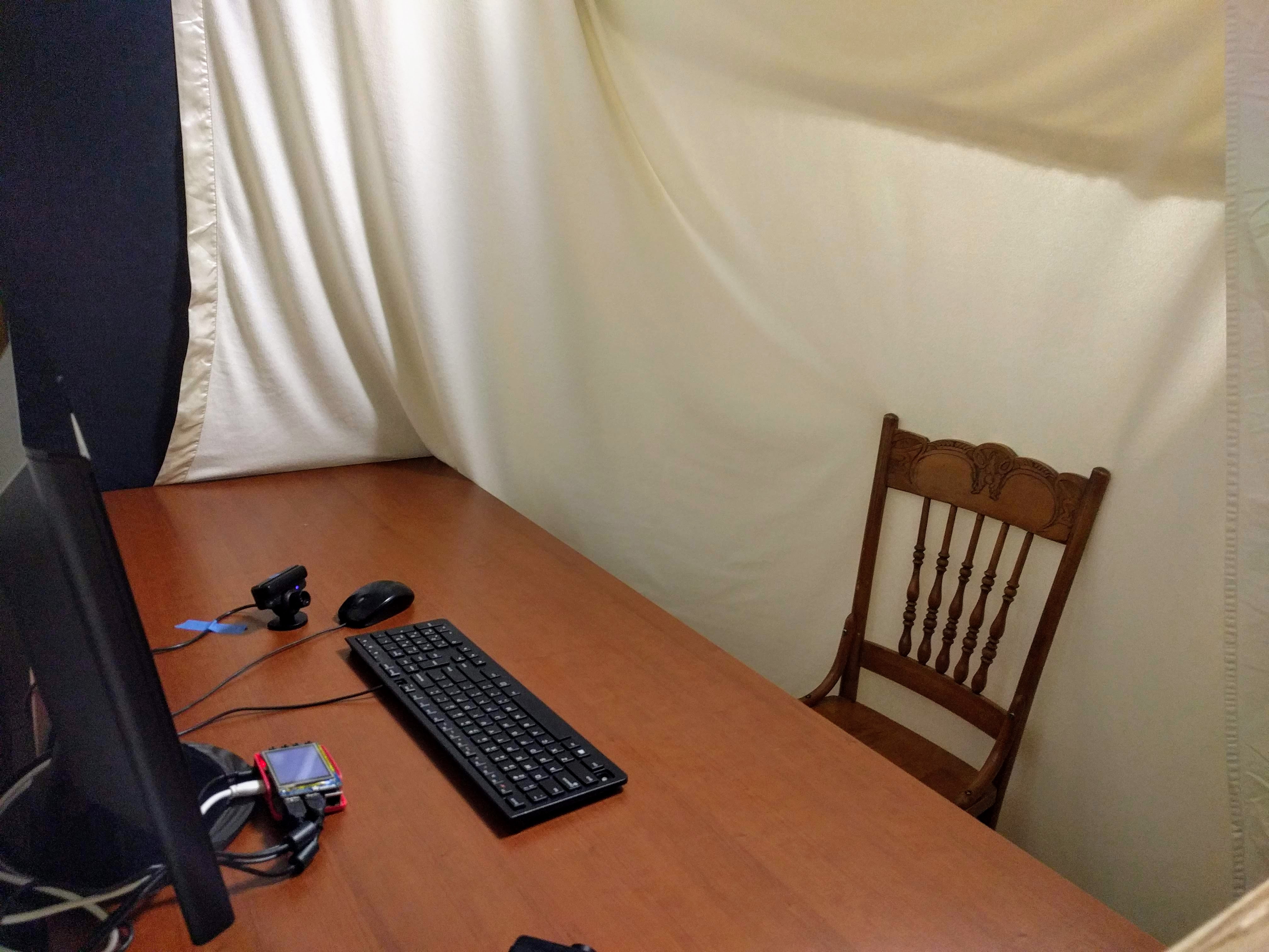
Figure 4. A white blanket was hung behind the theremin playing station to provide a neutral background for the hand-tracking software.
At this point, we had all the pieces necessary for implementing a hand-tracking algorithm. All that remained to do was to adapt the [4] software into something that would suit our needs. The first major adaptation was expanding that software to use video feeds from two webcams. A python class, DualWebcamVideoStream, was written to serve this purpose. This drew on what was learned in writing live_feed.py and was motivated by the findings of Tsao and Chang, who used the imutils package’s WebcamVideoStream class to speed up their video processing pipeline [1], [5]. The idea behind WebcamVideoStream is that a background thread constantly grabs new video frames from the webcam in a loop. Then, an external thread can access the most recent video frame by calling the read() method. DualWebcamVideoStream is almost a direct copy of WebcamVideoStream, but expanded to grab frames from two webcams. Beyond that, DualWebcamVideoStream has another important modification, prompted by the OpenCV documentation:
The primary use of cv2.VideoCapture.grab() is in multi-camera environments, especially when the cameras do not have hardware synchronization. That is, you call cv2.VideoCapture.grab() for each camera and after that call the slower method cv2.VideoCapture.retrieve() to decode and get frames from each camera. This way the overhead on demosaicing or motion jpeg decompression etc. is eliminated and the retrieved frames from different cameras will be closer in time.
So, DualWebcamVideoStream does precisely this for grabbing and retrieving frames from the two webcams.
Later, as development continued and we tested the integrated system, we observed randomly occurring segfaults that would crash our program, typically at the completion of the calibration procedure. We suspect this may be related to the handling of threads in DualWebcamVideoStream, but maybe not. Sometimes we’d see terse, inscrutable error messages relating to video capture printed to the terminal before the segfault. Perhaps these error messages are being issued from within OpenCV, or perhaps from within the video driver -- it is difficult to tell without lots more digging. Fortunately, these segfaults were rare enough not to significantly impede development progress.
The next adaptation of the [4] software was to build color histograms for each hand tracked, and for each camera. This is a one-time step that must be performed before hand tracking can begin; we call this step the “calibration procedure”. The reason different histograms are constructed for each camera for a given hand is that the lighting conditions seen by each camera might be different, resulting in a different color profile for the same hand, even when the two cameras are the same model.
In the calibration procedure, each histogram is built sequentially. To do this, a live video feed from the camera of interest is displayed on the main monitor, and a grid of boxes is overlaid on that video display. The user holds up their hand to the camera such that the overlay boxes fall on top of the hand in the video display; the user then presses enter. The histogram is then built by the software by sampling the pixel values within those boxes. After that, the video display shows hand tracking for that (hand,camera) combination only, by overlaying an outline of the hand (as detected) and its centroid in the camera's video display. The user is given the opportunity to redo the histogram build (by pressing ‘N’ for No) or else accept it (by pressing ‘Y’ for Yes). This procedure then continues for building a histogram for the same hand as seen by the second camera. After that, the procedure continues for building histograms for any other hands to be tracked, for both cameras. After all histograms have been built, the software then shows the tracking for all hands in both cameras, by displaying outlines and centroids for each hand in the video displays for both cameras. If there are any tracking errors, the user can restart the procedure all over (by pressing ‘N’ for No); otherwise, the results are accepted (by pressing ‘Y’ for Yes) and the calibration procedure is complete.
The histograms are themselves just arrays held in memory and are written to file with NumPy’s savetxt() function for later recall by loadtxt() when the theremin begins playing mode [13]. Each histogram file is saved in the current user’s home directory (/root when running with sudo) in a subdirectory called .vbp_theremin. The files themselves are named hist_hand_X_cam_Y.txt, where X and Y give the hand number (1, 2, 3, or 4) and camera number (1 or 2), respectively.
For building these histograms, the original [4] software samples pixels in 9 separate 10×10 pixel regions of interest. This results in histograms being built for 900 pixels. In an effort to speed up the hand tracking, we reduced this to just 4 separate 10×10 pixel regions of interest. While this does not seem to degrade the software’s hand-tracking ability (likely thanks to our use of brightly colored gloves), it is unclear whether, or to what extent, it improves the speed of the hand tracking algorithm. We didn't have time to objectively measure the impact of this change.
The goal of hand-tracking is to produce X, Y, and Z coordinates of each hand from what is seen by two cameras. As already mentioned, the [4] software computes a “centroid” for each hand relative to the video frame. For video frame i (where i is 1 or 2 for the left and right cameras, respectively), each centroid is some ordered pair (xi,yi), where xi ranges from 0 to wi (the width of the video frame, in pixels), and where yi ranges from 0 to hi (the height of the video frame, in pixels). In this coordinate system, (0,0) and (wi,hi) correspond to the top-left and bottom-right of the video frame, respectively. Before computing the X, Y, and Z coordinates for a hand, the centroids are first transformed as follows:
- ui = 2xi / wi - 1
- vi = 1 - 2yi / hi
This means that ui ranges from -1 (left side of video frame) to +1 (right side of video frame) and vi ranges from -1 (bottom of video frame) to +1 (top of video frame), with (ui,vi) = (0,0) corresponding to the center of the video frame.
Next, the transformed centroids for each hand are then combined as follows to compute the overall hand position:
- X = (u1 + u2) / 2
- Y = (u1 - u2) / 2
- Z = (v1 + v2) / 2
This mapping from centroids to hand positions results in X, Y, and Z ranging from -1 to +1. This mapping also corresponds to the axes shown in Figure 2. Specifically:
- When a hand moves in the positive X direction, its centroids in both video frames move to the right (u1 and u2 both increase).
- When a hand moves in the positive Y direction, its centroid in frame 1 (from the left camera) moves right (u1 increases) while its centroid in the frame 2 (from the right camera) moves left (u2 decreases).
- When a hand moves in the positive Z direction, its centroids in both video frames move upward (v1 and v2 both increase).
While this mapping from centroids to hand position is a bit crude, we found it to be rather effective for our proof-of-concept video-based theremin. However, initial experience with this mapping did show that it was difficult to exercise the entire playable range of our instrument. For example, when X was mapped to instrument pitch, we found it was necessary to move one's hand quite far to the left to get low pitches and vice versa for high pitches. Therefore, we decided to apply one final tweak to the mapping: a sigmoid function. The idea is to have a slope greater than one close to the origin, so that movements about the origin on any axis would result in greater changes in the corresponding audio effect. The benefit of a sigmoid is that it asymptotically approaches +1 to the left of the origin and -1 to the right of the origin, allowing us to maintain the -1 to +1 range for X, Y, and Z. We decided to use the error function (erf(·)) as our sigmoid (Figure 5). After considering different compression factors, we decided to go with 1.8 as it yields a good slope close to the origin (covering 80% of the playable dynamic range in only 50% of the physical playing distance along a given axis), and has negligible error from ±1 at the outer extents. We found that this made the instrument significantly easier to play, in terms of being able to exercise the entire playable range for any given audio effect.
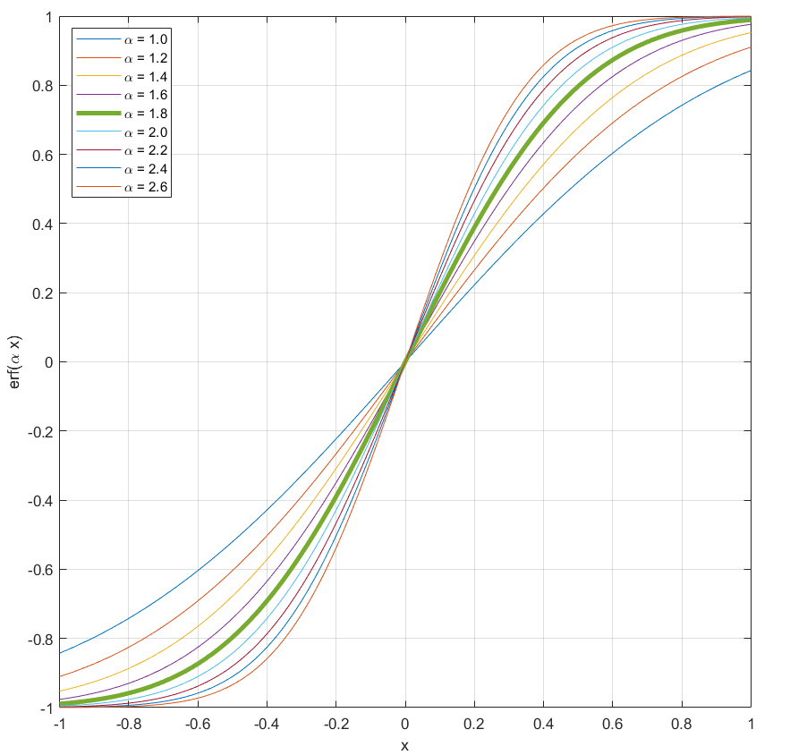
Figure 5. The error function with different horizontal compression factors (α), plotted from -1 to +1. We used α = 1.8 (the thick green curve) to improve the playability of our instrument.
Now that we had a working hand-tracking algorithm, the question is, how responsive is it? Our system is intended to be just like any other musical instrument, where playing motion is met with immediate audio response from the instrument. Experience with testing the final, integrated system showed it to be rather laggy (between hand movements and audio response), with an obvious quantization of hand tracking (as displayed in the X, Y, Z readouts in the GUI). The following test results capture performance of the hand-tracking software (Figure 6). These test results were captured with the software running by itself, without the audio synthe sis subsystem running. The position reporting rates were recorded without video displays running, as would be the case when playing theremin. The statistics were gathered by initializing a time stamp, incrementing a counter variable every time a spot in a loop was reached (one for the video capture loop, the other for the position reporting loop), and printing out a rate every time at least a second had elapsed since the last time stamp. After printing out the rate, the time stamp was updated, and the counter was reset. 75 rate printouts were gathered and averaged for each metric in this table. Also, the average time between printouts is given.
| Dual Webcam Frame Rate |
Hand Tracking: Position Reporting Rate | ||||
|---|---|---|---|---|---|
| 1 Hand | 2 Hands | 3 Hands | 4 Hands | ||
| Mean (Hz) | 29.66 | 7.26 | 7.48 | 7.50 | 7.39 |
| Std Dev (Hz) | 0.68 | 0.06 | 0.06 | 0.10 | 0.45 |
| Mean Δt (sec) | 1.02 | 1.10 | 1.07 | 1.07 | 1.06 |
Figure 6. Test Results for Video Capture and Hand-Tracking Algorithm
The webcam frame rate is quite close to the specification for the PlayStation Eye: 30 Hz. The hand-tracking position rate is much slower, at just over 7 Hz in all cases. It’s probably safe to say that the hand-tracking algorithm imposes at least a 1/7 second delay between movements and reported position. And it will not be able to track particularly rapid hand movements. What is rather interesting is to see that the position reporting rate actually increased, going from one hand tracked to two and three hands tracked, despite the fact that tracking additional hands requires more processing. A possible explanation for this phenomenon is that, due to the increased CPU load, the operating system allots more CPU time to the process when it starts to consume more CPU resources. Notice also that the mean time between rate printouts from the test went down, as the number of hands tracked increased. This is probably indicative of more frequent servicing of this process by the CPU scheduler. This suggests that this system may benefit from implementation with the real-time kernel PREEMPT_RT.
Audio Synthesis
The audio synthesis subsystem (i.e the synthesizer) was designed to create and control one monophonic tone for each hand tracked by the computer vision subsystem. Due to concerns about aliasing due to video frame rate and intermittent audio latency of the hand-tracking algorithm, the synthesizer was not designed to generate tones (i.e. in a loop) based on incoming inputs from the hand-tracking subsystem. Instead, the synthesizer receives inputs from the GUI to set up a synthesizer voice for each hand, and then pre-generates tones using those voices at zero volume. Subsequent input from the video system then adjusts the pitch, volume, and/or low pass filter cutoff frequency for a given voice. This way the audio system would continue playing the tone(s) at the previously-set levels while a new level setting was received and then processed.
Several utilities were explored for audio synthesis and controllability with minimal latency. The first was Fluidsynth, an open-source software synthesizer application [6]. This is commonly used in homemade MIDI synthesizer projects that use the Raspberry Pi. Fluidsynth plays an existing MIDI file using SoundFonts, files that contain pre-recorded audio samples of various musical instruments. However, in this sense Fluidsynth does not offer "true" synthesizer functionality as does the theremin, which generates sound electronically. Aside from the drawback of straying from the theremin’s principle of audio synthesis, using pre-recorded sounds also poses the risk of noticeable artifacts during playback if the audio were to be filtered (as we planned to do).
Furthermore, after much struggling with installing sub-libraries and linking together relevant files, another issue was discovered. Fluidsynth kept failing to recognize various imported SoundFont files, as shown in Figure 7.
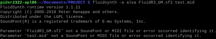
Figure 7. Error message when calling Fluidsynth. The application and various SoundFonts were reinstalled multiple times with no luck.
Subsequently, Fluidsynth was abandoned and another application with "true" synthesizer functionality was explored. This library, PyAudio, is also commonly used by MIDI hobbyists [7]. However, with this library, we were only able to generate poor quality sounds (riddled with delays, crackling, and other audio artifacts).
Finally, we discovered Sonic Pi [8]. This application, created by Sam Aaron, is a lightweight, single-file install. Sonic Pi offers an interface based on the Ruby programming language, and offers several pre-optimized high-quality tones, generated live, mimicking popular synthesizer sounds. Sonic Pi’s interface resembles an IDE based on the Ruby programming language, and is designed as a tool for live performance by musicians. It even allows for live modification of code, with execution that can be synced-up to a rhythm.
We decided to use Sonic Pi for the audio synthesis subsystem due to its emphasis on live music performance (with low latency and high-quality sounds). Another factor in our decision was the ease of troubleshooting. Sonic PI offers an IDE-like graphical user interface, with a built-in debugger, event logs, and a live Fast Fourier Transform (FFT) visualization of playing audio, as shown in Figure 8.
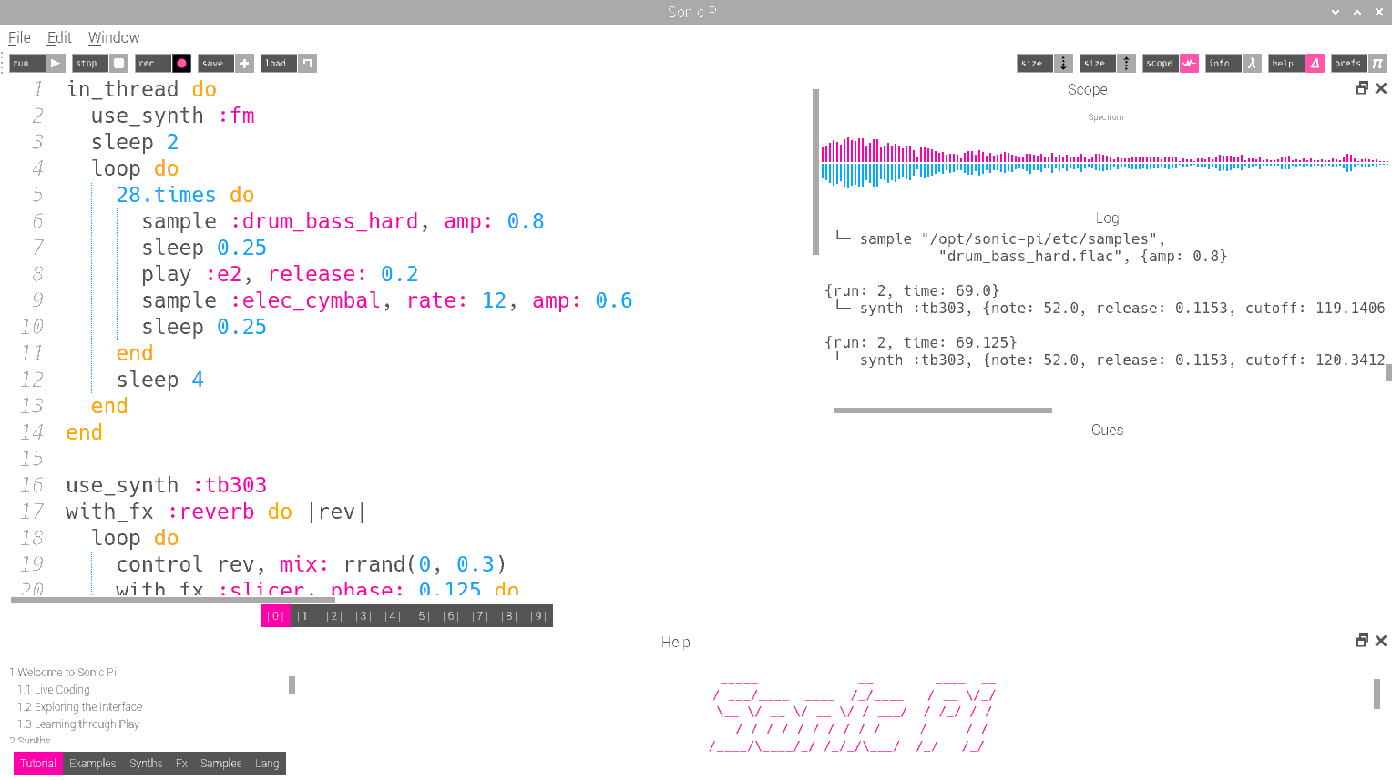
Figure 8. Sonic Pi, running an example script from source [8], written in Ruby. FFT visualization is shown in the top right. Event logs are on the middle right. Note that numerical values can be set for "amp" (i.e. volume), "rate" (i.e. tempo), release (i.e. fade-out), and sleep (i.e. delay).
Finally, in the context of presenting the video-based theremin as something musicians would consider, we felt Sonic Pi offered musicians transparency into the code underlying their audio synthesis, which opened up additional dimensions to interact with our instrument. Example scripts from the Sonic Pi website [8] were loaded into Sonic Pi to validate functionality of the application. One such script is shown in Figure 8. Uninterrupted, high-quality music playback was confirmed. We had our synthesizer.
The Audio Synthesis subsystem was coded within Sonic Pi, with the following overall design scheme:
- Initialize a list of five possible synths ("synths" being electronically-generated instruments)
- Once a command containing synth selections arrives to Sonic Pi locally-running server, initialize up to four voices (i.e. channels) with the appropriate synth, at zero volume.
- Once a command containing audio parameter values arrives, set audio parameters appropriately for the channel indicated in the command.
- If a "quit" command arrives, kill (i.e. silence and stop) all four synths.
Audio Control
Sonic Pi can receive commands via a protocol called OSC: Open Sound Control. OSC transmits data between Sonic Pi and other programs using UDP (User Datagram Protocol). While UDP is typically used for communication over the Internet, Sonic Pi allows the use of UDP between processes on the same device, by setting up a local server on the Raspberry Pi at IP address 127.0.0.1. This is the IP address Linux assigns for local interprocess network communications. This way, local programs can send UDP messages to that IP address, while Sonic Pi listens for UDP messages at that address. UDP messages need to include a port number, which directs the message to the appropriate receiving process.
Sonic Pi listens for UDP messages on port 4560. Incoming messages sent to this port are displayed in the event log in the GUI. To test this functionality, a simple test program was written in Sonic Pi. This program generated a tone, and then applied changes to pitch as commands were passed to Sonic Pi via an OSC-based Python script, which in turn polled a rotary encoder connected to Raspberry Pi GPIO pins 19 and 26. The receiver-side Ruby code used by Sonic Pi is provided in Code Appendix A, while the sender-side Python code is provided in Code Appendix B. The rotary encoder wiring is expounded in Figures 9 and 10.
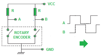
Figure 9. Circuit schematic of rotary encoder wiring. "A" and "B" are connected to GPIO pins 19 and 26, respectively. "VCC" and "GND" are connected to the "3V3" and "GND" pins on the Raspberry Pi, respectively. Resistor value R was chosen as 10 kΩ ±1%.
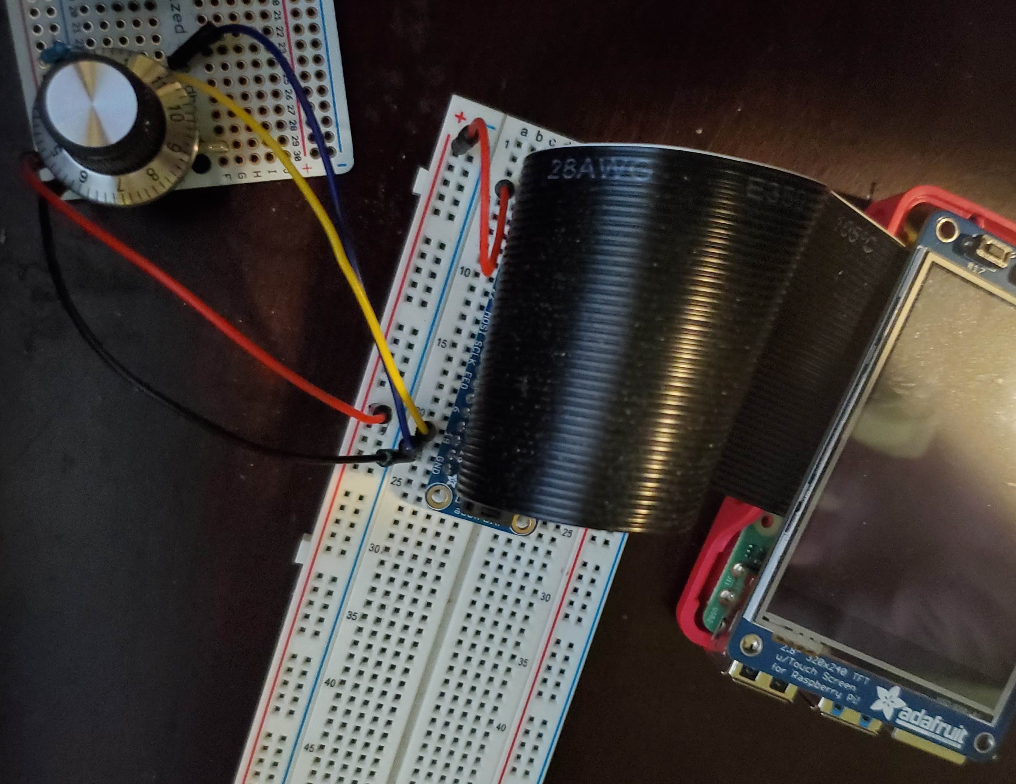
Figure 10: Image of rotary encoder connection to Raspberry Pi, as described in Figure 9.
Running both programs concurrently, OSC control was validated by successful audible pitch changes upon turning the rotary encoder. Print statements in the Python program output the pitch value at each click of the rotary encoder, as shown in Figure 11. These values corresponded to audible changes in pitch.
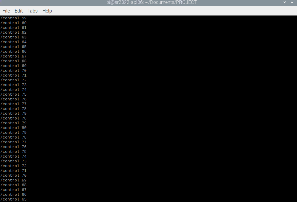
Figure 11: Response to rotary encoder input as output by the program given in Code Appendix B.
Altering the changed parameter in Sonic Pi from “note” to “amp” resulted in an audible change in volume while pitch remained constant. Similarly, altering the changed parameter to “cutoff” resulted in audible change in tone harmonics.
Now that pitch, volume, and cutoff control was validated, the program outlined in the Audio Synthesis section was developed. The ability to select the synth was tested by modifying the Python script to temporarily accept command line arguments. The Sonic Pi and Python programs were then run concurrently, producing the result shown in Figure 12.
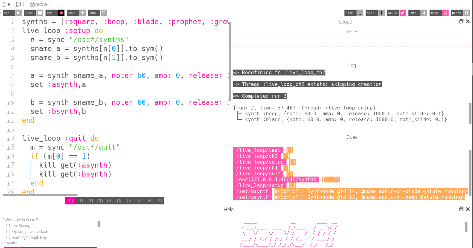
Figure 12. Result of synth-select test. Note the events in the event log, showing successful setting of synths for channels 1 and 2.
Sending a UDP message in the form “[1, 2]” triggers the “setup” loop to set one channel to the “blade” synth (index 1 in the list of synths) and other channel to the “beep” synth (index 2 in the list of synths). This process is visible in the event log shown in Figure 12.
Before integration with the video system, the ability for polyphonic control was tested. Specifically, the functionality tested was the ability to play and control multiple voices, each with three parameters set. Using the Python script that accepted command-line text arguments, two voices were initialized and controlled simultaneously. The successful performance of this test is shown in Figure 13.
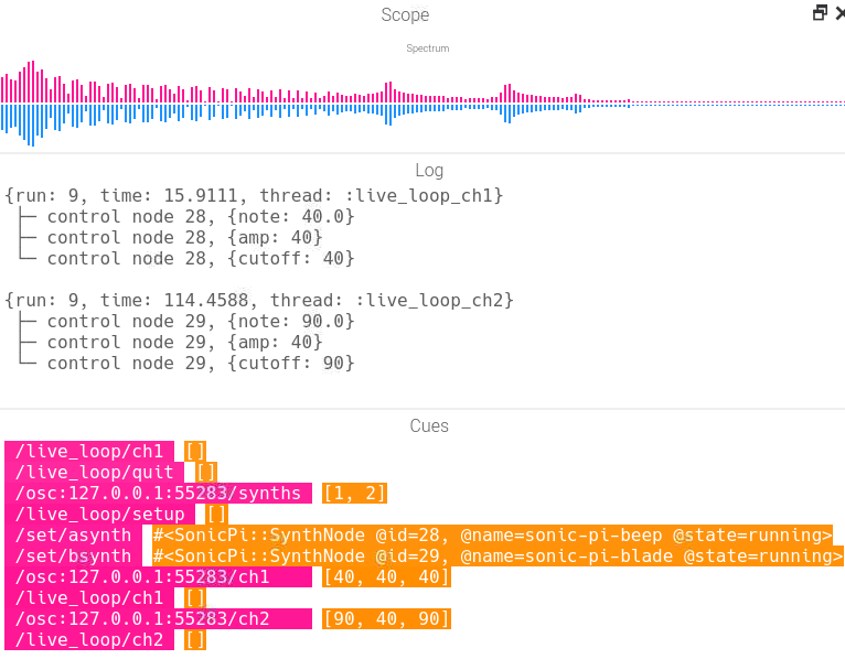
Figure 13. Result of polyphonic test. Note the events in the event log, showing successful setting of synths for channels 1 and 2. Also note setting of channel 1 to note 40, volume 40, and cutoff 40; and setting of channel 2 to note 90, volume 40, and cutoff 40.
This test produced two audible notes with different pitches, with audio parameters adjustable via text input. In Figure 13, note the FFT graph, which shows two peaks: one at a low frequency, and the other at a higher frequency. And as expected, harmonics appear at higher frequencies due to the interaction between the two fundamental frequencies.
Graphical User Interface (GUI)
The intention of the graphical user interface (GUI) is for it to run on the PiTFT touchscreen and serve as the user’s only point of interaction for theremin setup and configuration, with interaction during instrument play being via the tabletop webcams (with the GUI providing visual feedback). Of course, the calibration procedure of the hand-tracking subsystem and Sonic Pi (which must be up and running for audio synthesis to take place) both run on the desktop main display (i.e. HDMI monitor), but the overall vision of the video-based theremin is for it to run on the Raspberry Pi in headless mode, with the GUI displayed on the PiTFT. Ideas for fully achieving this vision (obviating the HDMI monitor) are addressed in Future Work.
The GUI was implemented with the PyGame library. Aaron drew heavily on code he developed for labs two and three during the semester in his development of the GUI, refining various techniques and Python classes he wrote for that prior work. His work on the GUI was also very much informed by his experience developing GUIs with GTK [10] in prior industry work.
Most of the GUI element classes implement the following methods:
__init__: a constructor which takes apygame.Rectas its first argument to specify the bounds of the object's layout, and sets the object as initially invisibleset_visibleandget_visible: to set and query the object’s current visibility, which controls whether it can be drawn on screen and can respond to touchscreen eventsdraw_on: asks an object to draw itself on given apygame.Screenargument. Objects that aren’t currently visible do nothing. Objects that own other GUI objects call those objects’draw_onmethod.register_event: used for responding to touch-screen events (thepygame.MOUSEBUTTONDOWNandpygame.MOUSEBUTTONUPevents), to activate buttons. Objects that are not currently visible ignore this function. Objects that own others (for example,PlayScreenowns a fewButtons and one or moreVoiceDisplays) recursively call their owned objects’register_eventmethod. Other objects simply implement the function as a no-op.cleanup: only used by objects (e.g.VolumePopup) that interact with the GPIO system to clean up GPIO port settings at program completion.
Additionally, button-like classes (Button and VoiceDisplay) implement set_enabled, which sets whether these objects can be activated (“pressed”) or not. This is different from visibility; buttons can be visible (drawn on screen) but disabled, meaning that they don’t respond to screen touches. This is useful for blocking actions which, due to the current GUI state, are not valid.
The high-level GUI operates as a finite state machine (Figure 14). The state determines which object(s) owned by the GUI are currently visible.
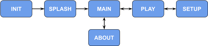
Figure 14. Finite state machine for the GUI.
At GUI startup, a splash screen with program information (Figure 15) is displayed for a few seconds. This corresponds to the SPLASH state in Figure 14.
Figure 15. The splash screen, which also doubles as an About screen (with the addition of a done button for the latter), displays for a few seconds at GUI startup.
Then a main menu appears (Figure 16); this corresponds to the MAIN state in Figure 14. The menu provides access to multiple theremin playing configurations (e.g. one hand, one voice, or two hands, two voices), as well as access to an about screen, which is merely the splash screen with the addition of a done button. The about screen corresponds to the ABOUT state in Figure 14.
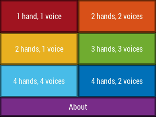
Figure 16. The GUI main menu.
Selecting one of the playing options from the main menu leads to a play screen (Figure 17), corresponding to the PLAY state in Figure 14. The play screen contains a button to return to the main menu, a play/stop button whose color and icon changes depending on whether the instrument is currently in configuration mode (stopped) or playing mode, and a calibrate button which leads to the calibration procedure for the current theremin configuration. Below this are the “voice displays”. Each such display contains the name of the instrument voice (i.e. Sonic Pi synthesizer name), which hands are controlling the voice, and X, Y, Z position readouts for the hands that control the voice. The position readouts are static when the instrument is not being played. They begin updating after the video system begins reporting hand positions at the start of playing mode.
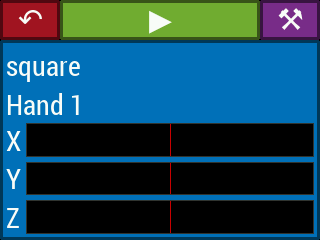
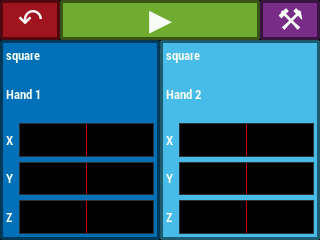
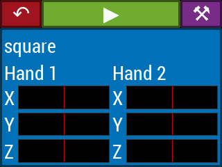
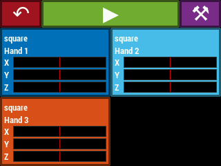
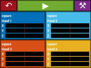
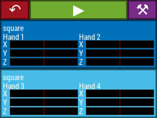
Figure 17. The various play screens accessible from the GUI main menu.
Each voice display is itself a button which leads to a setup menu for that voice (Figure 18), which corresponds to the SETUP state in Figure 14. The setup menu background color matches the background color of its corresponding voice display on the play screen for continuity. The red X cancels all changes (reverting to all previous configurations) while the green checkmark confirms changes. Both of those buttons return to the previous play screen.
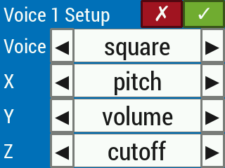
Figure 18. A setup menu for a single voice controlled by one hand (three control axes).
In the current version of the video-based theremin, the X, Y, and Z control axes of one or two hands (depending on the voice configuration) can control at most three effects per voice: pitch, volume, and low pass filter cutoff. The setup menu will not allow the user to confirm changes (by disabling the green checkmark button) if more than one control axis is controlling the same effect (Figure 19). Control axes can be set to control nothing, but at least one control axis must be set to control one effect (Figure 20). If, for example, the only effect to be controlled is pitch (Figure 21), then the other two effects (volume and low pass filter cutoff) are held at constant, nonzero values throughout playing mode.
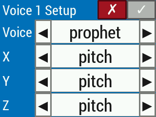
Figure 19. Setting multiple control axes to control the same effect causes the checkmark button to be disabled.
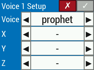
Figure 20. Setting all control axes to control nothing causes the checkmark button to be disabled.
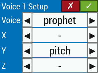
Figure 21. It is valid for some control axes to control nothing, so long as at least one control axis is mapped to one audio effect.
Once changes are confirmed in the setup menu, the GUI returns to the previous play screen. If the calibration procedure needs to be run, the green play button will be disabled (Figure 22). After completion of the calibration procedure, the green play button is enabled. When it is activated, play mode begins. The play button is changed to a red stop button, while the back and calibrate buttons, and each voice display button, are disabled, since their functions cannot be accessed while playing the instrument. Once the hand tracking system begins reporting hand positions to the GUI, the hand position bar graphs update accordingly. Pressing stop halts the hand tracking and audio synthesis, and the play screen returns to configuration mode, with all buttons enabled.
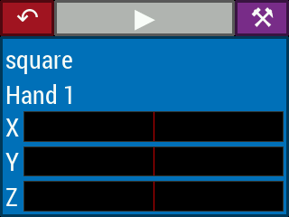
Figure 22. The play button is disabled if calibration of the hand tracking system is needed to proceed. The calibration procedure is initiated by pressing the purple button in the upper right corner of the GUI.
With the intention of running the video-based theremin on the Raspberry Pi in headless mode, we incorporated a volume control into the GUI, which is operated by PiTFT buttons 22 and 23 for volume up and down, respectively. The volume control popup, shown in Figure 23, displays for a few seconds following the last volume button press. The volume control can be used during the MAIN, PLAY, and SETUP states of Figure 14.
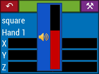
Figure 23. The volume popup displays for a few seconds following the last volume button press. PiTFT buttons 22 and 23 provide volume up and down control, respectively.
When the volume control is used, the GUI makes calls to amixer. At startup, the GUI calls amixer scontrols to determine the name of the simple volume control amixer can set, and later, when the volume is raised or lowered in the GUI, the GUI calls amixer sset -M <control name> <volume percent>. Unfortunately, we found that the volume control system on Raspberry Pi is rather complicated. While it may look cool, this feature unfortunately does not actually work.
System Integration
Before the theremin application is started, Sonic Pi must be started, and a Ruby script, sonicpilooper.py, must be loaded in the Sonic Pi GUI. This prepares Sonic Pi to receive commands from the theremin application.
The theremin application itself is started by running theremin.py. This launches the GUI, which runs on the PiTFT. When this happens, the HDMI display goes blank.
The first time the theremin application is run, no calibration files for the hand-tracking subsystem will exist. Therefore, when a play screen is accessed from the GUI main menu, the play button will be disabled, as in Figure 22. In order to proceed with playing the theremin, the user must run the hand-tracking calibration procedure. (Even if calibration files exist from a previous use of the application, it is good practice to run the calibration procedure anyway, since glove colors, hand configurations, or lighting conditions generally change from one calibration to the next.) This is initiated by pressing the purple calibrate button. Upon doing so, the PiTFT GUI temporarily goes blank, while the HDMI display comes back up, displaying two video feeds from the two cameras. After proceeding through the calibration procedure and accepting the results, the HDMI display again goes blank and the PiTFT GUI resumes display. At this point, the play button on the play screen is enabled, as in Figure 17, allowing play mode to be initiated. Pressing the play button does this.
The following provides more detail of what is depicted in Figure 1. The GUI owns a single SonicPiInterface object. This object maintains a UDP socket to send commands to port 4560 at IP address 127.0.0.1, which is connected to Sonic Pi's OSC server. At the beginning of playing mode, the GUI registers all configurations (synthesizer voices, the numbers of the hands controlling each voice, and the corresponding audio effects for each voice) with the SonicPiInterface object. The GUI then asks this object to start play, which 1) sets up default audio effect values for any effects not being controlled, and 2) sends the appropriate command to the Sonic Pi OSC server to begin running the synthesis loop script. After this, the GUI starts up the hand-tracking subsystem in a separate process using Python’s multiprocessing library, passing a reference to the SonicPiInterface object. The GUI sets up a duplex pipe between itself and the hand-tracking subsystem. The GUI listens to this pipe to receive hand coordinate updates to display on the play screen while the instrument is being played; it also issues a terminate command via this pipe to the hand-tracking subsystem when the stop button is pressed on the play screen. (The hand-tracking subsystem must be careful to monitor for this command before it sends new coordinate updates.) The hand-tracking subsystem uses the SonicPiInterface object it received to send commands to Sonic Pi to update audio effects. The reason why we didn’t put a pipe between the hand-tracking subsystem and the audio synthesis subsystem is that Sonic Pi already receives control via UDP packets sent to the OSC server. We figured it would only introduce extra latency for the hand-tracking subsystem to send coordinate updates into a pipe, only for those to be subsequently translated into audio commands and transmitted through a UDP socket to Sonic Pi. So instead, the hand-tracking subsystem uses the SonicPiInterface object to map the coordinates it produces into appropriate audio control commands, and send those to the Sonic Pi UDP server.
The hand-tracking subsystem reports X, Y, and Z coordinates each in the range of -1 to +1, with -1 and +1 corresponding to the outer edges of the cameras’ collective field of view. The audio control subsystem uses nonnegative values that range up to a certain maximum, depending on which effect is being controlled. So the SonicPiInterfaceobject takes care of the mapping, and also ensures that effects that were not set up for hand control in the GUI receive default values. This prevents the situation of, for example, a voice being completely silent when nothing has been assigned to control its volume.
In the GUI, when the stop button is pressed, the hand-tracking subsystem is signaled to stop via its pipe connection to the GUI. The top-level python function for that process eventually exits and the process terminates. The GUI also asks the SonicPiInterface object to stop play, which 1) sends a quit message to Sonic Pi and 2) clears all settings that were applied at the beginning of play mode.
Results
With the functionality shown in the demonstration video, we achieved all the goals outlined in the objective. We have shown a proof-of-concept with polyphonic audio synthesis using video-based control input, hand-motion interaction similar to that of the theremin while utilizing off-the-shelf hardware, and audio control with user-configurable mapping to the three orthogonal spatial axes. We were also able to show predictable control of three audio parameters with minimal audio artifacts. The final product does suffer from some performance issues, with significant latency between hand movements and updates to the audio output, and inability to track rapid hand movements (due to sample rate limiting). Nevertheless, the final product meets all the requirements we described in our original proposal.
Over the course of this project, we had to explore and then discard a few publicly-available tools for the video and audio systems, due to various limitations. However, in the end, we were able to find tools that (with some modification) let us achieve our goals.
We were able to stay on-budget by relying primarily on loaned supplies and by spending less than ten dollars on new parts, substantially less than the $100 maximum specified for this project.
Conclusion
In this project, we proceeded in an incremental manner, building a basic version of each subsystem and testing it for basic functionality, and then adding layers of complexity while testing at each step. We found that, while controlling audio via text input or encoders produced clear and non-noisy output, using video information introduced substantial noise from various sources. After several attempts to demonstrate consistent control as a function of motion despite erratic hand-tracking behavior, we decided to create a low-noise environment using a white backdrop, neutral-colored clothing, and brightly-colored gloves. This yielded satisfactory results (see the demonstration video).
Work Distribution
Aaron was responsible for implementing the video-based hand-tracking algorithm using OpenCV, all aspects of the GUI, and most aspects of system integration, including the SonicPiInterface class. Shreyas implemented the audio synthesis program using Sonic Pi, as well as the audio control interface for Sonic Pi using Python-OSC and UDP communication, and assisted with system integration.
Future Work
This project yielded a final product which meets the basic specifications and initial ideas we laid out: a configurable instrument that is played with hand motions tracked by video cameras. However, much work remains to be done for this to be a product that someone might actually want to use as a playable instrument.
- Hand tracking algorithm update rate and latency: The biggest issue with our project is that it isn't very responsive to hand motion. The primary reason for this is the slowness of the hand tracking algorithm which, as we saw from testing, provides hand position updates at about 7.5 Hz. Although the hand tracking system runs in its own process, this alone is obviously not enough to provide the desired performance. At a minimum, we'd like to see the update rate pushed to 20 Hz. This may require spawning four subprocesses to divide the algorithm work among the cores of the Raspberry Pi. It might also require using and leveraging the features of the PREEMPT_RT kernel. Finally, it will probably require analyzing the bottlenecks in the existing code, which involves many calls to OpenCV routines. There are probably ways to make the algorithm faster without sacrificing robustness. Perhaps our approach of using colored gloves (as opposed to tracking skin which tends to result in a lot of false positives) allows for a leaner hand tracking algorithm. It might also be worthwhile to go with an entirely C++-based approach.
- Audio control latency: The other major contributor to slow responsiveness comes from Sonic Pi. Shreyas observed a latency of up to half a second between sending a UDP control command and response from Sonic Pi with what he heard. A delay of this magnitude is unacceptable for a playable musical instrument: imagine a trombone player attempting to play a rapid musical passage, but having the sound coming out the bell responding to slide movements from half a second earlier! We're not sure if there is any way around this issue with Sonic Pi. So solving the issue might require finding a better alternative to Sonic Pi, or more difficult still, writing something from scratch.
- Multi-threading in Sonic Pi: Sonic Pi does support multi-threading, which might allow us to have control for each voice running in separate threads. Possibly combining this with the PREEMPT_RT kernel would improve Sonic Pi latency in polyphonic playing modes. We didn't experiment with this due to lack of time.
- Eliminate hand tracking glitches: One possibility to do this would be to quantize the hand positions, so that position noise, when small enough, is quantized away. But this works against continuously-controllable pitch and audio effects, all desirable features of our current implementation. Perhaps there is a post-processing means to eliminate glitchiness; that is, allow the video system to make momentary mistakes (think a hand is somewhere it isn't), but use some follow-on algorithm to suppress glitchy updates. Maybe this would rely on something from control or estimation theory, like Kalman filtering.
- Eliminate the need for neutral backdrop: Unfortunately, this goal probably stands in opposition to the previous goal, in that it makes the video system more glitchy. But a useful instrument should be able to be played basically anywhere, instead of the controlled environment required by our product.
- Fine-tune hand position tracking: Our initial approach of computing hand position from hand centroids relative to video frames is admittedly crude, but works well as a proof-of-concept. However, the approach is not informed by stereoscopic computer vision techniques that could provide better insight into computing absolute hand position in 3D space based on what two cameras see. Another, related issue is that it should be natural for each hand to have its own "home position", i.e. a per-hand origin. (The current software uses some arbitrary point, somewhere in the center of the overall area of play, as the origin for all hands.) By supporting per-hand origins, audio effects could return to their defaults when the corresponding hand returns to its home position, instead of having to return to the center of the area of play.
- Discrete pitch control: Our theremin, like the original theremin, uses continuous pitch control, allowing one to play tones between semitones (the smallest interval between playable notes in Western music). This enables musical features such as pitch bending and glissandos. However, unskilled theremin playing can be fraught by many dissonant, out-of-tune notes, and moreover, continuous pitch control makes our instrument more susceptible to hand tracking noise. Therefore, it would be nice to have discrete pitch control, with glissando between notes, as configurable options.
- More audio effects: The initial system only supports modulation of pitch, dynamics (i.e. "volume"), and low pass filter cutoff frequency. We'd like to offer more audio effects, such as tremolo, vibrato, chorus, reverb, pan, wah-wah, Leslie speaker speed, etc.
- Run Sonic Pi server without Sonic Pi GUI: The current configuration of our theremin software requires Sonic Pi to be running the desktop app, complete with a GUI. However, we have no need to actually use the Sonic Pi GUI while playing the theremin; our software quietly sends UDP commands to the Sonic Pi server in the background while playing. Towards the end of our project development we came across Sonic Pi Tool [9], which can be used to start the Sonic Pi server as a daemon and ask that server to load a script. Although we verified this basic functionality from the command line, we didn't incorporate it into our product as we'd need additional time for testing and debugging. Accomplishing this goal would be a prerequisite for the next goal.
- Eliminate need for external display and keyboard: Initially, we didn't foresee the need to calibrate the video system. This step relies on OpenCV-spawned video displays to provide feedback to the user. It was most straightforward to just display these video feeds on an HDMI-connected monitor. Moreover, one of our classmates reported on Piazza that attempting to spawn OpenCV displays while using the PiTFT for display (in particular for Pygame) crashed their application, so using the external display was a good initial approach to sidestep this issue. However, our desire is for the entire user interface to be displayed on the PiTFT. Therefore, another goal for future work is to figure out how to display the video feed used in calibration on the PiTFT, thereby eliminating the need for the external display. At the same time, we'd incorporate the PiTFT buttons into the calibration sequence, instead of relying on keyboard events.
- Experiment with control by more than two hands: While we had the code set up for it, we were not able to demonstrate control with more than two hands. A next step in this project would be to test system latency and performance with two people playing the video-based theremin in the three- and four-hand configurations.
- Debug video system segmentation faults: While Aaron has ample experience tracing down segfaults in C/C++ programs using the likes of
valgrindandgdb, we're a bit out of our depth finding the source of segfaults in Python. This is something we simply did not have time to do.
Bill of Materials
A bill of materials for this project, which would be required for one starting completely from scratch, is as follows:
| What | How Many | Unit Cost | Total Cost |
|---|---|---|---|
| Raspberry Pi 4 Model B with 2 GB RAM | 1 | $35.00 | $35.00 |
| Raspberry Pi Power Supply 5.1V 3A | 1 | $7.95 | $7.95 |
| Raspberry Pi 4 Case | 1 | $6.00 | $6.00 |
| AdaFruit 320x240 2.8" TFT Display with Resistive Touchscreen | 1 | $34.95 | $34.95 |
| AdaFruit Pi Cobbler Plus Breakout Cable | 1 | $6.95 | $6.95 |
| SanDisk 16 GB Micro SD Card | 1 | $6.90 | $6.90 |
| PlayStation Eye Camera | 2 | $20.00 | $40.00 |
| Micro HDMI to HDMI Cable, 1 meter long | 1 | $8.95 | $8.95 |
| Rotary Encoder | 1 | $0.76 | $0.76 |
| Rotary Encoder Knob | 1 | $0.95 | $0.95 |
| HDMI monitor (on hand) | 1 | $0.00 | $0.00 |
| USB keyboard (on hand) | 1 | $0.00 | $0.00 |
| USB mouse (on hand) | 1 | $0.00 | $0.00 |
| Lab supplies (e.g. protoboard, resistors, wire) (on hand) | various | $0.00 | $0.00 |
| Software | oodles! | $0.00 | $0.00 |
| Total | $148.41 | ||
For this project, we had nearly all of these items on loan or on hand. The only things we purchased were a rotary encoder and an accompanying knob. Therefore, the actual amount we spent on this project was well less than $10.
References
- Air Painter, by Albert Tsao and Stephanie Chang
- Handy, hand detection with OpenCV, by Pierfrancesco Soffritti
- Opencv Python Hand Detection and Tracking, by BhaskarP6
- Finger Detection and Tracking using OpenCV and Python, by Amar Prakash Pandey
- imutils WebcamVideoStream, by Adrian Rosebrock and Andrew Dassonville
- FluidSynth, a SoundFont Synthesizer, by David Henningsson, Element Green, Pedro Lopez-Cabanillas, et al.
- PyAudio, by Hubert Pham
- Sonic Pi, by Sam Aaron et al.
- Sonic Pi Tool, by Emlyn Corrin
- The GTK Project
- Python 3
- OpenCV 4.4.0
- NumPy
- Pygame
- The color palette used in the GUI comes from MATLAB's default color order.
- The splash/about screen background color is Cornell's official red, Carnelian.
Code
The complete project source code is hosted on GitLab: https://gitlab.com/aplogan/polyphonic-video-theremin
Code Appendix A
# Sonic Pi OSC Receiver Test
s = play 60, release: 1000, note_slide: 0.1
live_loop :test do
    use_real_time
    n=sync "/osc*/control"
    if (n[0] != "QUIT")
        control s, note: n[0]
    end
    sleep 0.5
end
Code Appendix B
# Python OSC Sender Test
# OSC messages set pitch value as set by Rotary Encoder
#!/usr/bin/env python
# -*- coding: utf-8 -*-

from time import sleep
from pythonosc import udp_client
from pythonosc import osc_message_builder
from RPi import GPIO
import argparse
import sys

clk = 19
dt = 26
quitButtonPin = 17
GPIO_list = [clk, dt, quitButtonPin]

GPIO.setmode(GPIO.BCM)
GPIO.setup(clk, GPIO.IN, pull_up_down=GPIO.PUD_DOWN)
GPIO.setup(dt, GPIO.IN, pull_up_down=GPIO.PUD_DOWN)
GPIO.setup(quitButtonPin, GPIO.IN, pull_up_down=GPIO.PUD_UP)

value = 60
clkLastState = GPIO.input(clk)

quitNow = False
def GPIOquitButtonPin_callback(channel):
    global quitNow
    quitNow = True
    print("QUIT")
    GPIO.cleanup(GPIO_list)
    sys.exit()

GPIO.add_event_detect(quitButtonPin, GPIO.FALLING, \
    callback=GPIOquitButtonPin_callback, bouncetime=200)

parser = argparse.ArgumentParser()
parser.add_argument("--sp", default="127.0.0.1", help="Sonic Pi input port")
args = parser.parse_args()
spip=args.sp
print("Sonic Pi on IP:",spip)
sleep(2)
sender = udp_client.SimpleUDPClient(spip,4560)
print("udp sent")

while not quitNow:
    clkState = GPIO.input(clk)
    dtState = GPIO.input(dt)
    if (clkState != clkLastState):
        if dtState != clkState:
            value += 1
        else:
            value -= 1
        if value > 0:
            sender.send_message('/control',value)
            print("/control",value)
        else:
            print("INVALID")
    clkLastState = clkState
    sleep(0.01)

GPIO.cleanup(GPIO_list)