SLAM Mapping Robot
ECE 5725 Final Project, Dec.13th 2019
A Project By Bingjia Wang (bw499) and Yunyun Zhang (yz2625).
Demonstration Video
Introduction
Over the last decades, numerous applications of mobile robots have been introduced in the market, and they could be found in diverse scenario, such as households, industrial, educational and military, where they have been designed for various purposes and learning different tasks. With the dramatic improvement on the precision, the cost of robots have been increased at the same time. We designed a low-cost mapping and localization robot. We used Raspberry Pi, piTFT, IMU, wheel encoder and ranger to achieve area dimension and altitude measurement functionalities and showed real time result on piTFT screen.
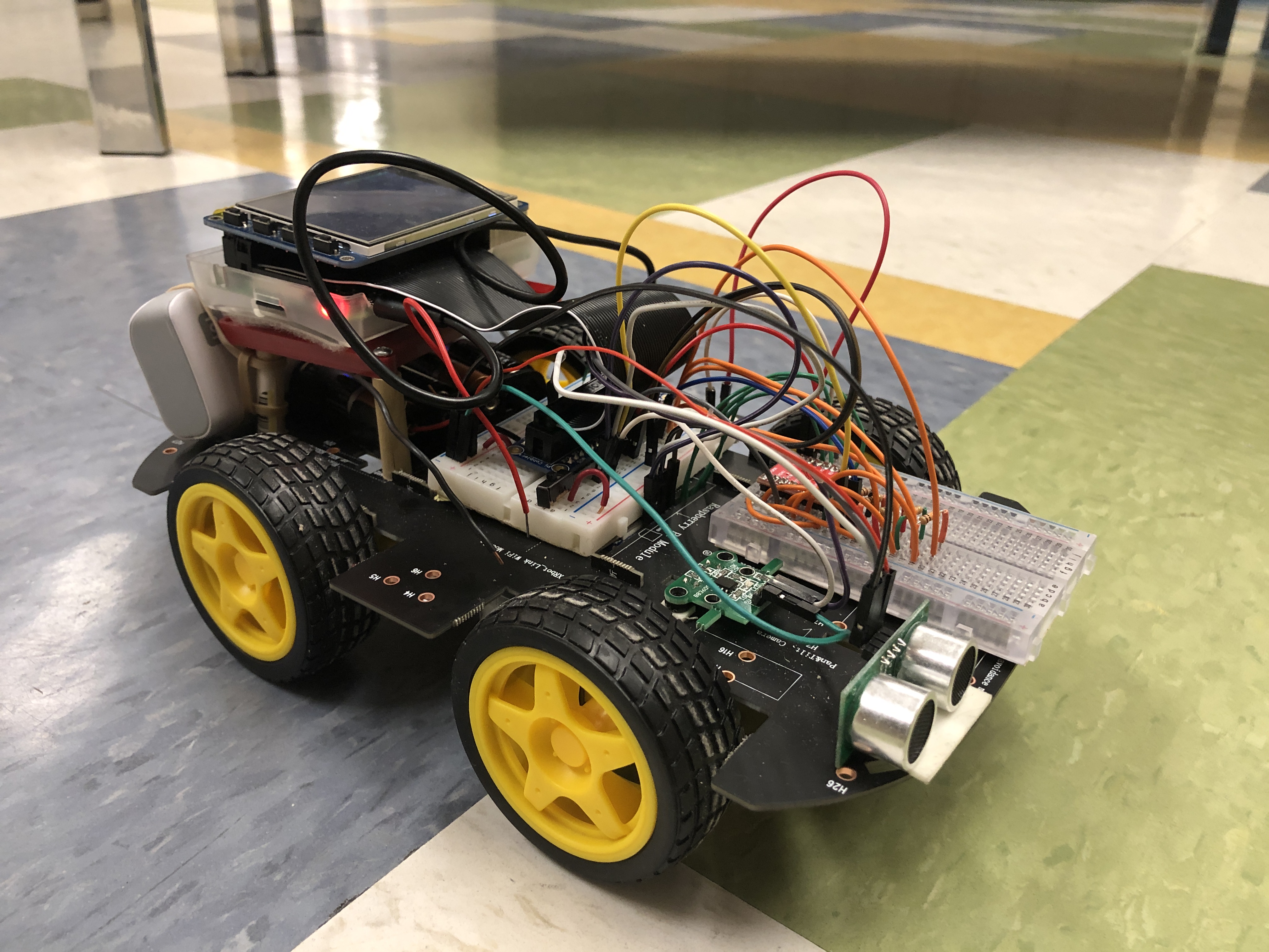
Final Product
Project Objective:
- Design route to let the robot car’s moving range cover the whole area set in advance.
- Measure the dimension and altitude of the area.
- Show the altitude measurement and robot car’s motion on piTFT in real time.
Design & Testing
Route
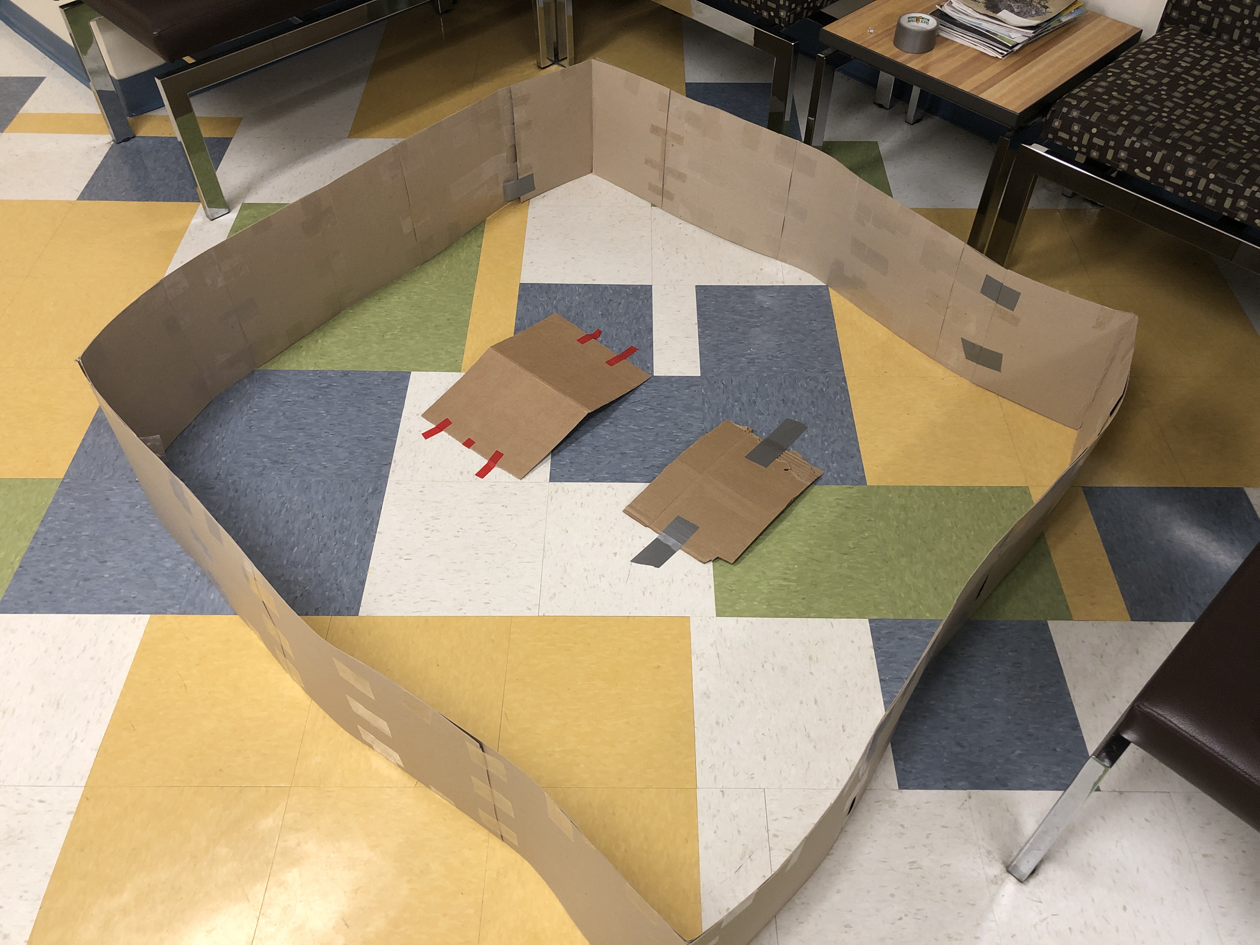
Testing area was set to be in rectangular shape. In order to cover the whole area and get the dimension, the robot first moved along the two edges to get the dimension of the testing area and followed by a ‘S’ route to scan the whole area and measure any altitude change.
Mapping
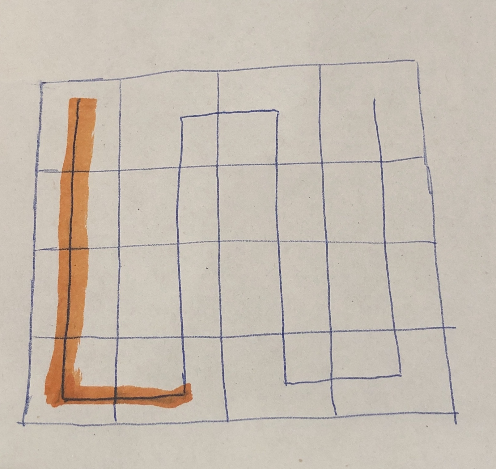
In order to show the robot’s current position, the testing area was divided into blocks. Because the dimension of the area was measured at first, the dimension of the block could be calculated. Based on the robot moving distance measurement, we could calculate which block the robot was in. We defined the unit moving distance as a “L” shape, which was the width of the area plus the length of the block. The quotient of robot moving distance divided by this unit distance indicated which column the robot was in, and the remaining indicated the robot’s position in that column.
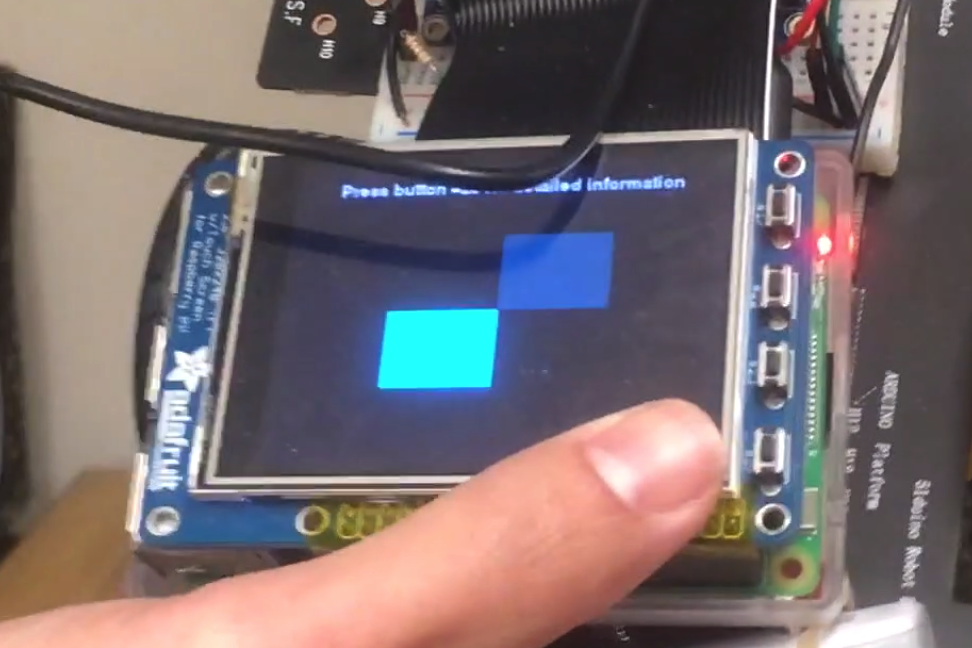
To show the robot motion and area altitude on piTFT, initially the whole screen was white (255, 255, 255) and when the robot moved to a new block, this block changed color accordingly. If the block contained no peak or slope, the color changed to black (0, 0, 0). Otherwise the block changed to a lighter color. In order to have better visualization on the PiTFT, we mapped the altitude only on the Blue and Green channel via the equation: 255*(Height/Max_Height), where Height was the altitude of the current block and Max_Height was the maximum altitude so far. So the block with maximum altitude had the color (0, 255, 255) and lower altitude block had smaller value in green and blue channel. Therefore, the lighter color implied higher peak in this area. A simulated mapping process including robot moving route and display on piTFT screen is shown below.
Heading Direction
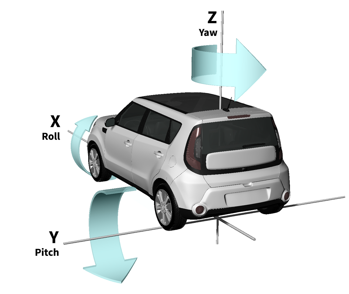
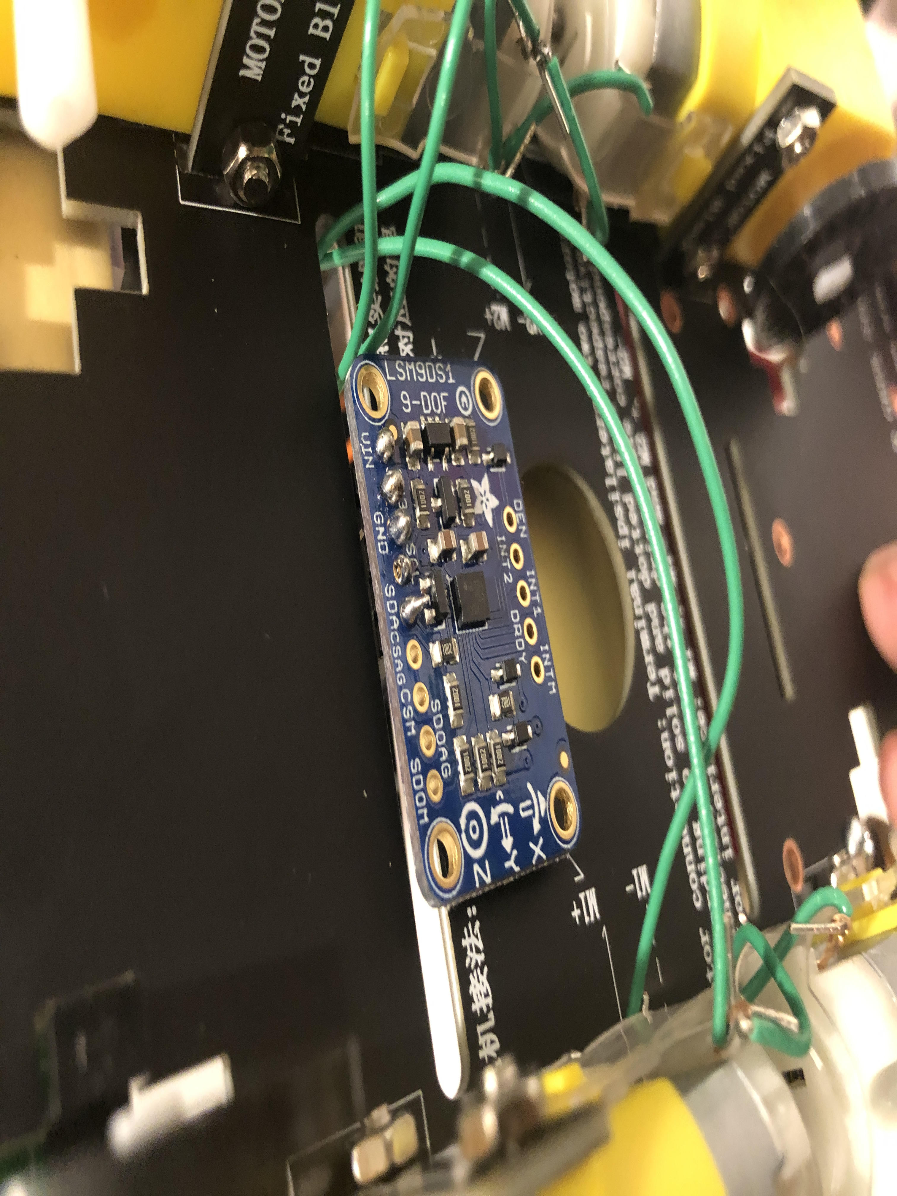
We used IMU’s gyroscope to measure the heading direction. Gyroscope measures the angular velocity on roll, pitch and yaw axes. Numerical integration on yaw axis yields the turning angle of the robot.
Drifting problem: The IMU measurements contain errors. Integrating measurements means errors are accumulated over time. This leads to ‘drift’: an error-increasing difference between calculated angle and actual angle.
In order to solve drifting problem, we used a low pass filter and Autoregressive(AR) model to clean the noisy measurement:![]()
where y is the filtered measurement, u is the raw measurement, w is cutoff frequency, t is sampling time and h is time-step.
By using this model, we got a more accurate angle calculation. But it caused another problem: because we referenced previous measurement to get the current value, the filtered measurement lagged behind the actual value, which was crucial in our project since we needed yaw angle to determine whether the robot has turned 90 degrees. In order to solve this problem, we proposed two solutions.
- Instead of using gyroscope, we tried to use IMU’s magnetometer to get the yaw axis angle. The formula is:
 , where y is the pitch axis magnetometer measurement and x is roll axis measurement.
This formula gives a yaw angle between 0 and 360 degrees. The advantage was that it avoided integration and the errors didn’t accumulate. So there was no time lag problem. However, the disadvantage was that the noise affected the measurements heavily. Especially in an indoor environment, the metal around made the measurement super inaccurate and the reading varied a lot if measure location was changed. Although we used hard iron and soft iron offset removal to calibrate the magnetometer, it was still highly unstable. So we had to find another solution. - Basically, the robot needed to turn 90 degrees each time (the u-turn in ‘S’ route can be divided into two right angle turn). We added an adjustment step after the turning step. Because of the time lag, the calculated angle difference between start and end of right angle turn was less than 90 degree. So the threshold we set during the turing step was less than 90 degree and was determined through experiment. After the turning, we let the robot move forward for a little bit (about 1 second) to let the filtered calculated angle catch up with the actual current angle. If the angle difference between angle before turning and current angle was still less than 90 degree, the robot turned again until it reached 90 degree turn. We also slowered the motor speed in order to let the filtered value catch up with current angle faster. By using this solution, the robot could make a right angle turn within 5 degree error.
Altitude Measurement
The altitude could be calculated by: moving distance on the slope • sin(pitch angle). Moving distance was measured by wheel encoder. Pitch angular velocity was measured by IMU’s gyroscope, and angle was calculated by numerical integration.
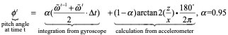
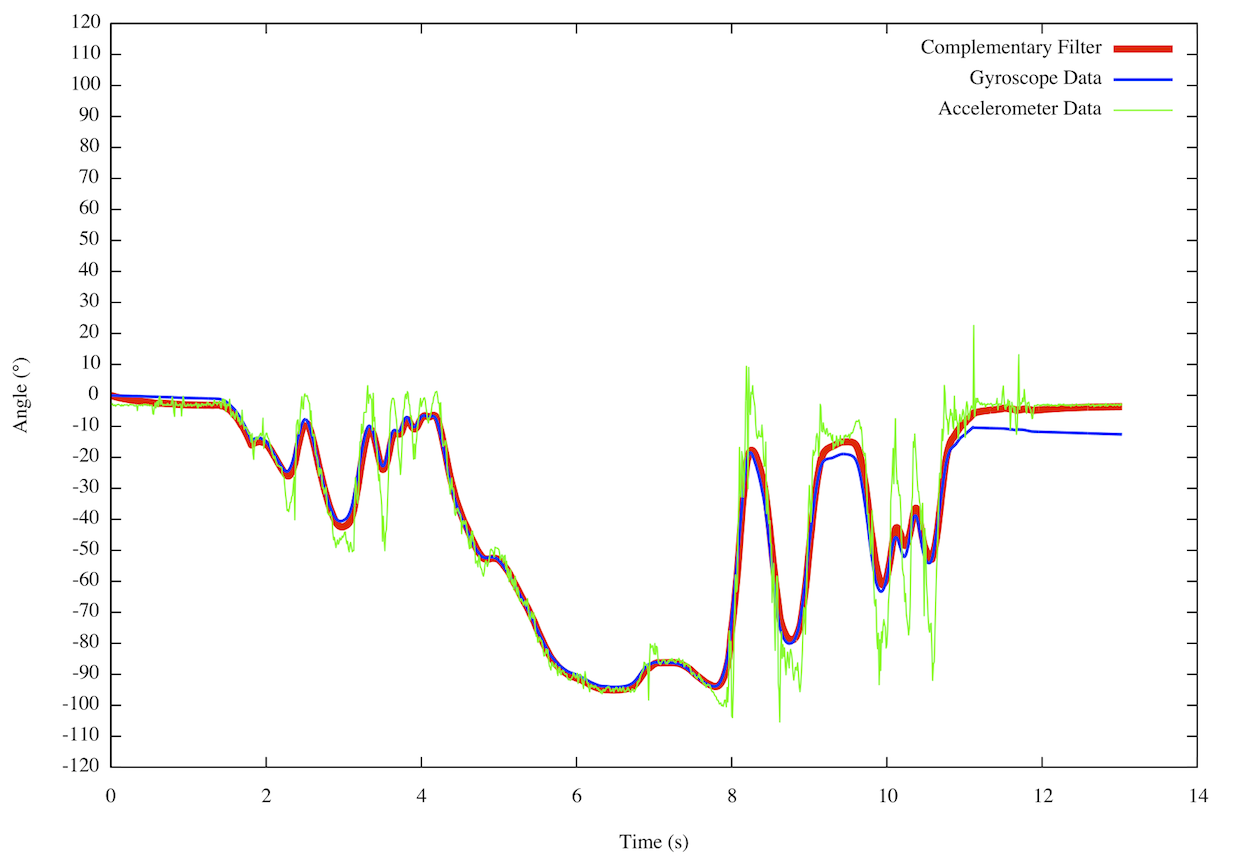
In order to make pitch angle measurement more accurate, we used sensor fusion with complementary filter to calculate the pitch angle, which means we combine accelerometer and gyroscope measurements to get the pitch angle.
Pitch angle could be calculated by using the accelerometer measurements on x-axis and z-axis(with 9.81m/s^2 gravity). We used arctan(z/x), where z and x were acceleration measurements on z and x axis, to get the slope angle based on accelerometer readings. We used the same low pass filter with AR model(for yaw angle) to filter the accelerometer measurements. The advantage was that it did not suffer from integration drift problem, and the z angle acceleration was relatively acuurate, since it was gravity. But the accelerometer readings on x axis was much less stable than gyroscope readings on IMU. Therefore, we used 95% gyroscope calculation result (same integration method in calculating yaw axis angle) and 5% accelerometer calculation result to get the final pitch angle. This complementary filter compensated the drifting problem by accelerometer calculation.
In summary, we used the formula below to get the pitch angle:
Distance Measurement
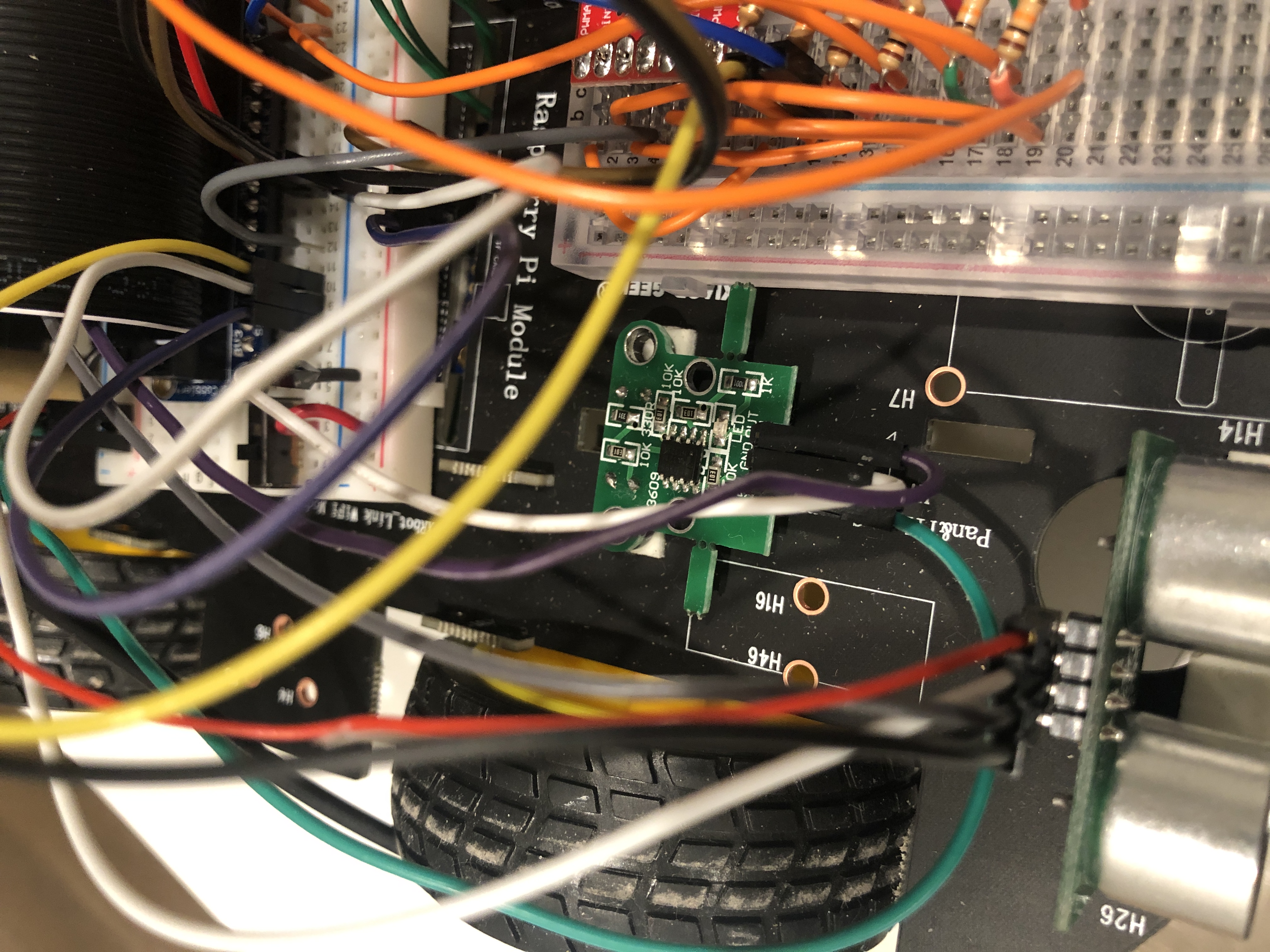

The distance was measured by wheel encoder. The sensor worked by mounting the spoked sensor wheel on the motor shaft. The U-shaped sensor assembly was then mounted so that it cradled the spoked sensor wheel. As the spoked sensor wheel rotated with the motor shaft, the spokes in the wheel interrupted the IR sensor beam and caused the sensor to output a series of pulses with one pulse for each of the 20 spokes in the wheel. An LED on the module flashed for each pulse. The wheel encoder calculated rpm by dividing the number of pulses by the time during these pulses. Then by knowing the diameter of the wheel, we could calculate the speed and distance. In our case , the wheel diameter is 4cm.
Edge Detection
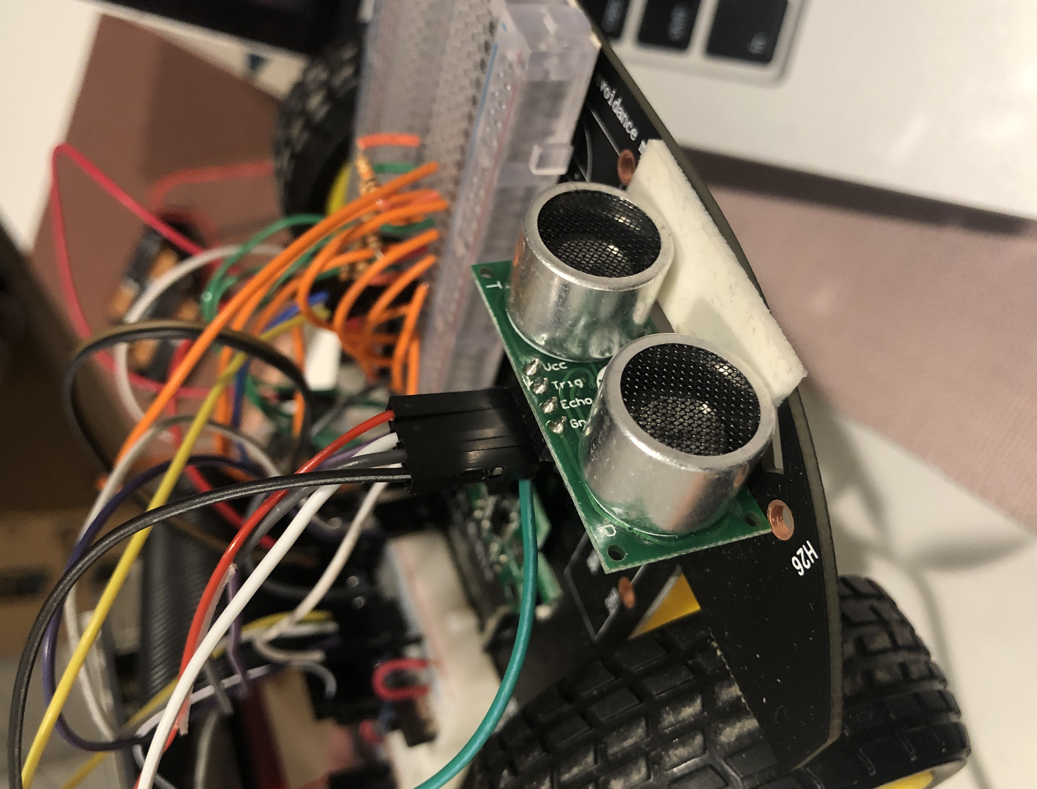
To avoid collision with edges, we used ranger to detect the distance between the head and the edge. If the robot was too close to the edge, it turned 90 degrees(when getting the dimension) or 180 degrees(when moving along “S” route).
Motor Driver
For the project, we first used one popular and well documented motor driver L298N, which is a dual-H bridge stepper module design. The driver connected to the RPi and 2 DC motors as following diagram.
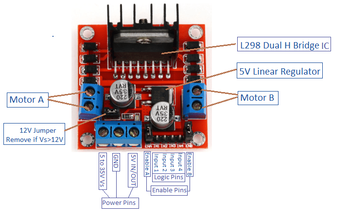
Based on the tutorial, the driver controls the DC motor speed via enable A and B by changing the PWM duty cycle and uses the Input 1,2 to control the rotation direction of the motor A, and input 3 and 4 for motor B. However, after several tests, the driver could only control the rotation of the motor, and suffered a lot of problems on speed control. The motor speed barely changed when duty cycle changed. At the beginning, the IMU algorithm did not require significant slow speed at turning movement. We used full speed for the whole route movement. However, after the change of IMU algorithm, the speed control became a crucial requirement during the whole process.
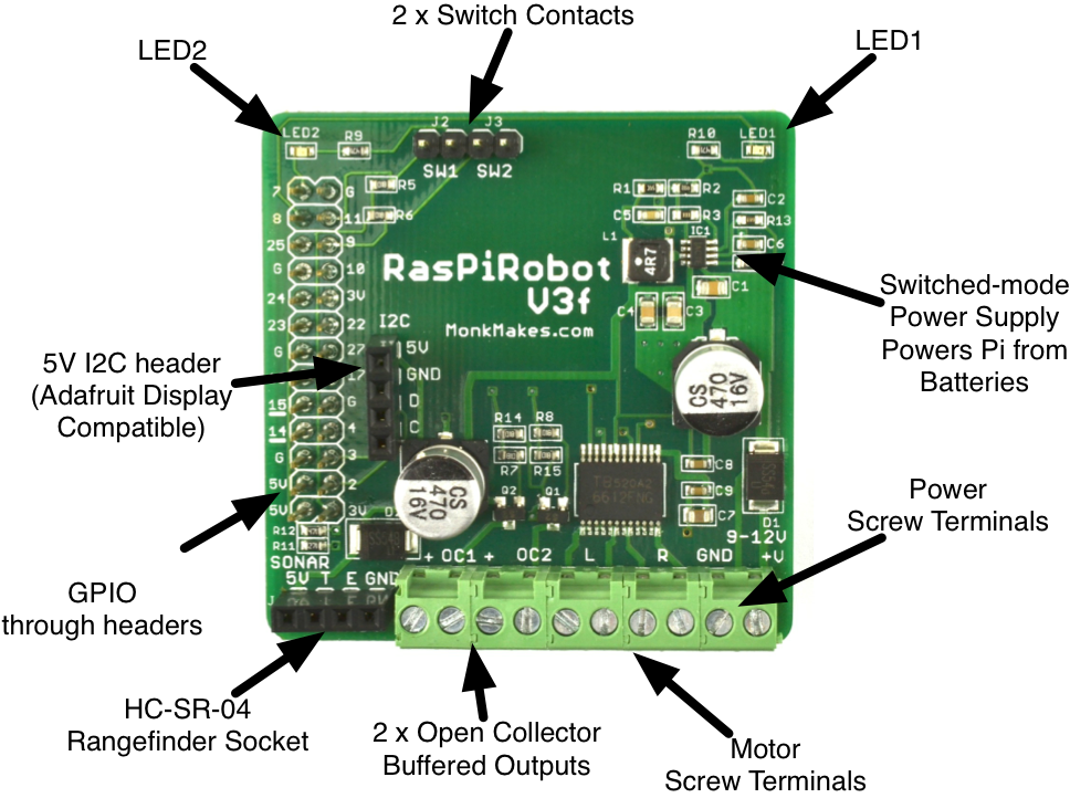
After a significant time of debugging the driver problem on speed control, we changed to our second choice on motor driver, RasPiRobot Board V3(RRB3), which is shown above. The first RRB3 driver we used had an inside failure. We could only control the LEDs on the driver but not the motors. So we tried with a second RRB driver using the same script, and this time we could control the motors. By using this motor driver, we could control the motor speed by changing the PWM duty cycle.
The datasheet indicated that this driver could power the Raspberry Pi if the driver input voltage is between 9v and 12v. So we used 8 AA batteries to charge the driver and Pi together. But using AA batteries caused voltage drop problem. The motor driver needed relatively high current, and AA batteries had more voltage losses at high current and so when the motors started up, the voltage arriving at the RRB3 dropped below the 6V or so needed to stop the Raspberry Pi rebooting. So we changed back to power Pi separately.
Another problem we found was that the motor started to slow down during the robot moving forward without changing the PWM duty cycle. So we measured the voltage between input and ground of the driver and we found that the voltage continued dropping from about 11v to 5v in less than 1 minute. So instead powering the motor driver by batteries, we used DC power supply in the lab to power the motor driver and measured the driver input voltage again. This time the voltage didn’t drop. So we suspected that there was a failure inside the driver causing the driver to burn off the batteries. Since we only had 2 RRB drivers, we had to switch to another type of motor driver.
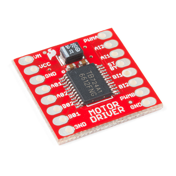
Finally, borrowed from another group, we changed to the third choice of motor driver, which was TB6612fng. After several tests, we could control the speed and rotation direction of four wheels as expected. The datasheet indicated that the driver input voltage is 5-12v, so we only needed 4 AA batteries. We assigned duty cycle ~ 40 at turning movement and ~ 60 at forward movement.
Result
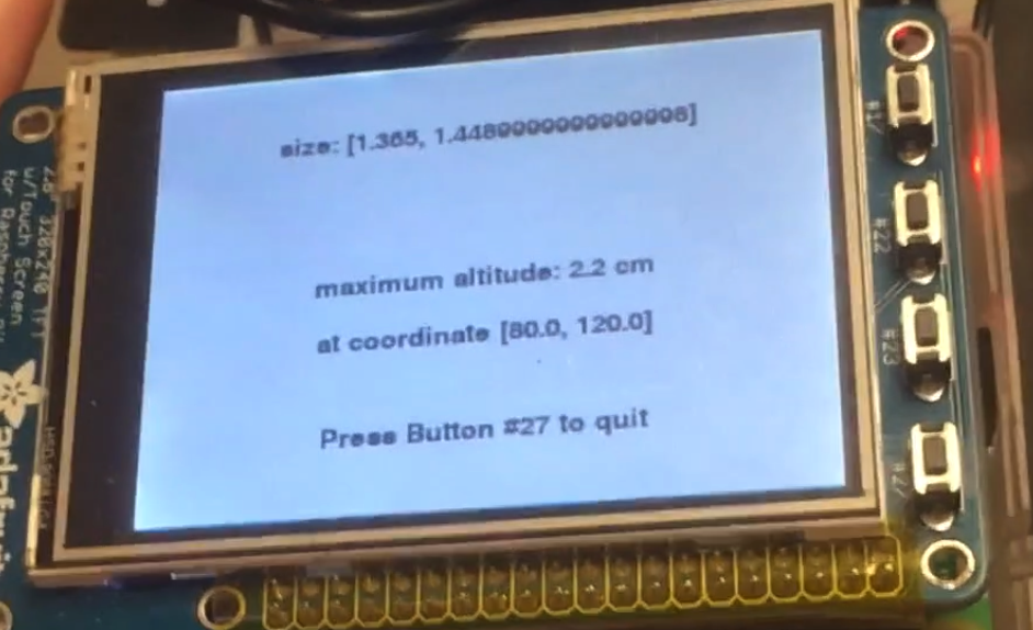
From the testing result, the map showed correct locations and colors of two peaks. Since the left peak was higher than the right one, the color of left peak block was lighter than right one. The detailed information showed the dimension of the testing area, which was approaximately correct compared with our measurement of the area (1.3m x 1.5m). It also showed the maximum altitude, which was 2.2cm. This result was also close to our measurement of the left peak, which was 2.5cm.
Conclusion
Overall, the project met all the objectives we listed and was able to show real-time mapping on the PiTFT. In the demo video, we could see that the area size measurement worked as expected. The mapping on piTFT followed the ‘S’ route and color implied correct peak heights. Moreover, the summary screen result showed that, the error rate of the altitude measurement was less than 10%.
Future Work
- Use accelerometer and GPS to track the movement.
- It can track tiny movement within a small area compared with traditional GPS only tracking method.
- Rapid movement feedback and more accurate position information. With more accurate movement tracking, we no longer need to use blocks to approximate positions, and we can get more accurate location coordinate.
- Improve the heading and altitude measurement accuracy by Extended Kalman Filter.
- One drawback of comlementary filter is that it can not be used to get yaw angle, since roll and pitch acceleration, unlike yaw acceleration, don't have gravity references. But extended kalman filter can be used to get both pitch and yaw angle.
- Initially the team planned to use extended kalman filter, which could provide more accurate and less latency response. However, due to the time limit, the team achieved sensor fusion with complementary filter.
- Design an iOS/Android app to remote control and visualize the mapping.
- Implement with Bluetooth/ Zigbee communication between phone and the robot.
- Control the robot using app.
- Show real time robot location and mapping result on app.
Work Distribution
Bingjia Wang
bw499@cornell.edu
System integration, position tracking, color mapping and testing
Yunyun Zhang
yz2625@cornell.edu
Individual sensor data acquisition, IMU filter implementation and testing.
Parts List
| Name | Picture | Price |
|---|---|---|
| IMU: 9 degree of freedom LSM9DS1 | 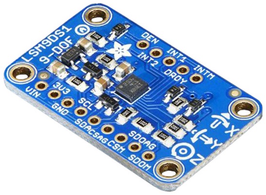 |
$14.90 |
| Wheel Encoder Kit | 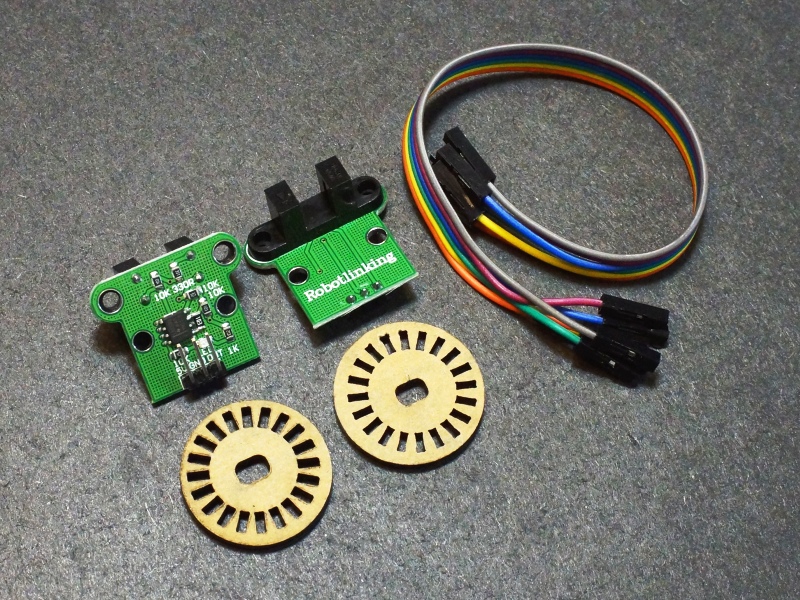 |
$9.99 |
| HC-SR04 Ultrasonic Sonar Distance Sensor | 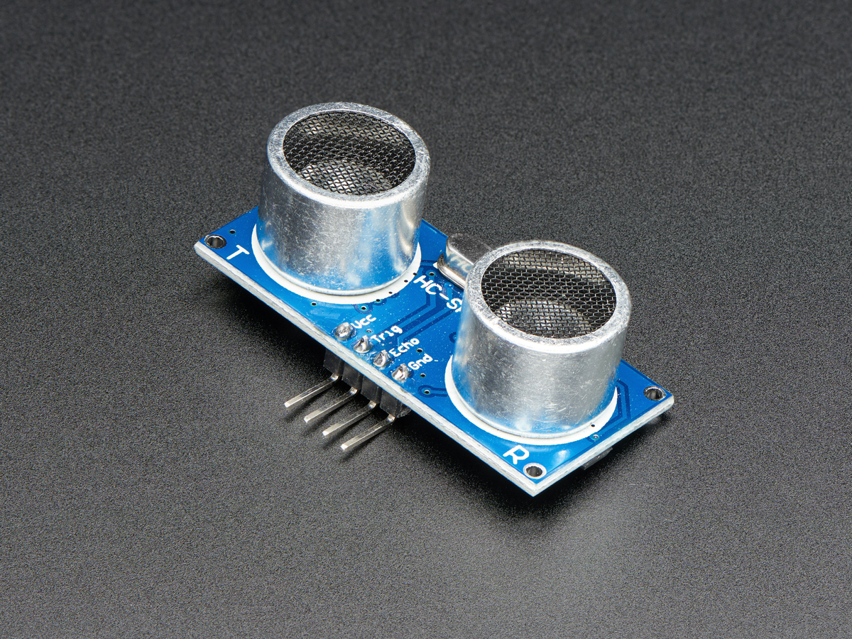 |
$3.95 |
| Wheel robot platform | 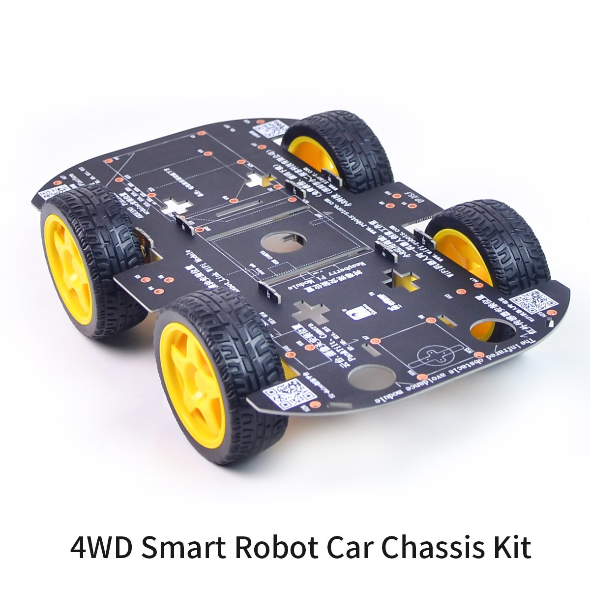 |
$24.99 |
| Motor Driver TB6612FNG | |
$4.95 |
| Raspberry Pi | 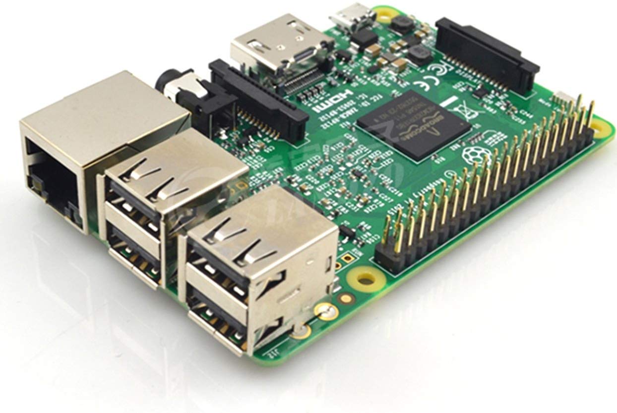 |
$35.00 |
| Total | $93.78 |
References
IMU Complementary FilterDiscrete-Time Lowpass Filter
HC-020K Motor Speed Sensor
RaspiRobot V3f Motor Driver
TB6612FNG Motor Driver
R-Pi GPIO Document