Final Project of ECE 5725
By Zhaoyi Luo (zl766) and Yingrong Zhu (yz2583)
Nov. 2019 - Dec. 2019
Facial Recognition and Crime Detection System (FRCDS) contains two parts: facial recognition and crime detection. The first part is a biometric technology based on human facial features for identification. We used a modern camera to gather facial graphics, automatically detected and tracked faces in the dataset. In this part, we finished our task with the help of the OpenCV library. The second part is to apply the previous achievement to practical applications. In our dataset, some faces will be labeled as a criminal and the system will trigger the audible alarm once those faces have been recognized. In this part, the audible alarm is consisted of a 16x32 LED matrix panel and a speaker.
We used a 16 GB micro-SD card with the Raspbian kernel version 4.14.58. To fully use all the available space on our card, we first expanded our filesystem by jumping into the “raspi-config” menu via the command sudo raspi-config. Followed by selecting “Advanced Options” and then “Expand filesystem”. Once prompted, we selected the first option “A1 Expand Filesystem”.
To update and upgrade any existing packages, we ran the command:
sudo apt-get update && sudo apt-get upgrade
To install some developer tools, including CMake to helps us configure the OpenCV build process, we ran the command:
sudo apt-get install build-essential cmake pkg-config
To install some image I/O packages to allow us to load various image file formats from disk, we ran the command:
sudo apt-get install libjpeg-dev libtiff5-dev libjasper-dev libpng12-dev
To install some video I/O packages to allow us to load various video file formats from disk, we ran the command:
sudo apt-get install libavcodec-dev libavformat-dev libswscale-dev libv4l-dev
sudo apt-get install libxvidcore-dev libx264-dev
To compile the highgui module, which is used to display images on our screen and build basic GUIs, we ran the command:
sudo apt-get install libgtk2.0-dev libgtk-3-dev
To optimize many operations inside of OpenCV, we installed a few extra dependencies and ran the command:
sudo apt-get install libatlas-base-dev gfortran
To compile OpenCV with Python bindings, we installed two Python versions and ran the command:
sudo apt-get install python2.7-dev python3-dev
Since we had installed all the dependencies we needed for the OpenCV, we were going to grab the OpenCV 3.3.0 from the official OpenCV repository. We ran the following commands:
wget -O opencv.zip https://github.com/Itseez/opencv/archive/3.3.0.zip
unzip opencv.zip
Besides, to get the full installation of the OpenCV, we also needed to grab the opencv_contrib repository as well. So we then needed to run the following commands:
wget -O opencv_contrib.zip https://github.com/Itseez/opencv_contrib/archive/3.3.0.zip
A virtual environment is a special tool used to keep the dependencies required by different projects in separate places by creating isolated, independent Python environments for each of them. To start with, we ran the following commands:
wget https://bootstrap.pypa.io/get-pip.py
sudo python3 get-pip.py
sudo pip install virtualenv virtualenvwrapper
sudo rm -rf ~/.cache/pip
After running the commands mentioned above, both virtualenv and virtualenvwrapper would be installed. Then we needed to update the ~/.profile file to include the following lines at the bottom of the file:
# virtualenv and virtualenvwrapper
export WORKON_HOME=$HOME/.virtualenvs
export VIRTUALENVWRAPPER_PYTHON=/usr/bin/python3
source /usr/local/bin/virtualenvwrapper.sh
To reload that file, we simply ran the command:
source ~/.profile
So far, we finished setting the environment variables. The next step was going to create the Python virtual environment that we would use for this project development. As the programming language we decided to use was Python 3, we ran the command:
mkvirtualenv cv -p python3
Once we finished all the setting mentioned above, we could drop down into our virtual environment by running the commands:
source ~/.profile
workon cv
If the environment was set successfully, we could see the text (cv) preceding our prompt. And we had to run the above two commands every time we opened a new terminal to make sure we were in the right virtual environment.
We installed some packages that we would use during the design:
To start our build by using CMake, we ran the following commands:
cmake -D CMAKE_BUILD_TYPE=RELEASE -D CMAKE_INSTALL_PREFIX=/usr/local -D INSTALL_PYTHON_EXAMPLES=ON -D OPENCV_EXTRA_MODULES_PATH=~/opencv_contrib-3.3.0/modules -D BUILD_EXAMPLES=ON ..
To increase the swap space size during compiling, we needed to enable the OpenCV to compile with all four cores of the Raspberry Pi without the compile hanging due to memory problems. What we should do was to open the file /etc/dphys-swapfile and edited the CONF_SWAPSIZE variable:
# CONF_SWAPSIZE=100
CONF_SWAPSIZE=1024
This change should be withdrawn once all the preparation works were done. To activate the new swap space, we ran the commands:
sudo /etc/init.d/dphys-swapfile stop
sudo /etc/init.d/dphys-swapfile start
To start the compiling process, we ran the command:
make -j4
To start the installing process after finishing the compilation, we ran the commands:
sudo make install
sudo ldconfig
Once we finished the above six steps, we opened a new terminal, executed the source and workon commands, and then finally attempted to import the Python and OpenCV bindings:
source ~/.profile
workon cv
python3
>>> import cv2
>>> cv2.__version__
'3.3.0'
The Raspberry Pi camera module is capable of taking full HD 1080p photos and videos. We first directly connected it to our Raspberry Pi via the connector situated between the Ethernet and HDMI ports. It should be inserted firmly into the connector, with care taken not to bend the flex at too acute an angle. After installed, we used our test code to test if the camera could run well.
We created a Python script named “simpleCamTest.py”, which can be found in our repositories. The test code could capture the video streaming created by the camera. Though we showed the streaming in RGB mode, it could also be shown in gray mode. While the script was running, we could exit the program by simply pressing the button Esc. Here is how it looks like:
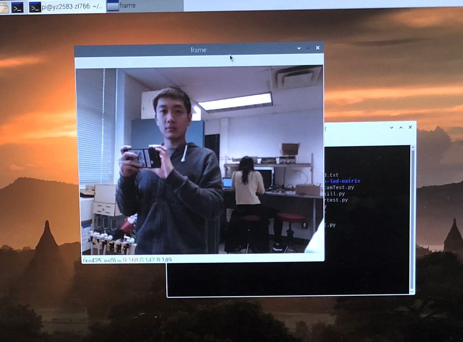
Figure 1 Simple Camera Test
The fundamental task of facial recognition is to detect faces. That’s to say, we have to capture human faces first, then to compare and recognize different faces in the future. The most common face detection method is to use Haar Cascade Classifier which is an efficient target detection method proposed by Paul Viola and Michael Jones in《Rapid Object Detection using a Boosted Cascade of Simple Features》. This machine learning method is based on a large number of positive and negative images. Initially, this method needs lots of positive (with human faces) and negative (without human faces) images to train the classifier by extracting features from the positive images. The classifier will firstly collect Harr features from images, then create integral images to facilitate the process, use Adaboost to train and organize features into cascade classifiers to form a strong classifier. But the good news is that the OpenCV library contains many pre-trained classifiers and recognizers that can be used to detect faces, eyes, mouths, etc.
We created a Python script named “faceDetection.py”, which can be found in our repositories. Here we used the default classifier to detect faces and called the camera in an infinite while loop. Inside the classifier function, we needed to input some important arguments such as gray, scale factor, minimum neighbor and minimum face size. Gray represents the images are grayscale. Scale factor represents the scale of each image grayscale. Minimum neighbor represents the number of neighbors that each candidate’s facial rectangle has. Minimum face size represents the minimum rectangle size for face detection. When a face is detected, this function will return a rectangle with the x- and y-axis coordinates at the top left corner coupled with the width and length. Here is how it works with a frame around Zhaoyi's face:
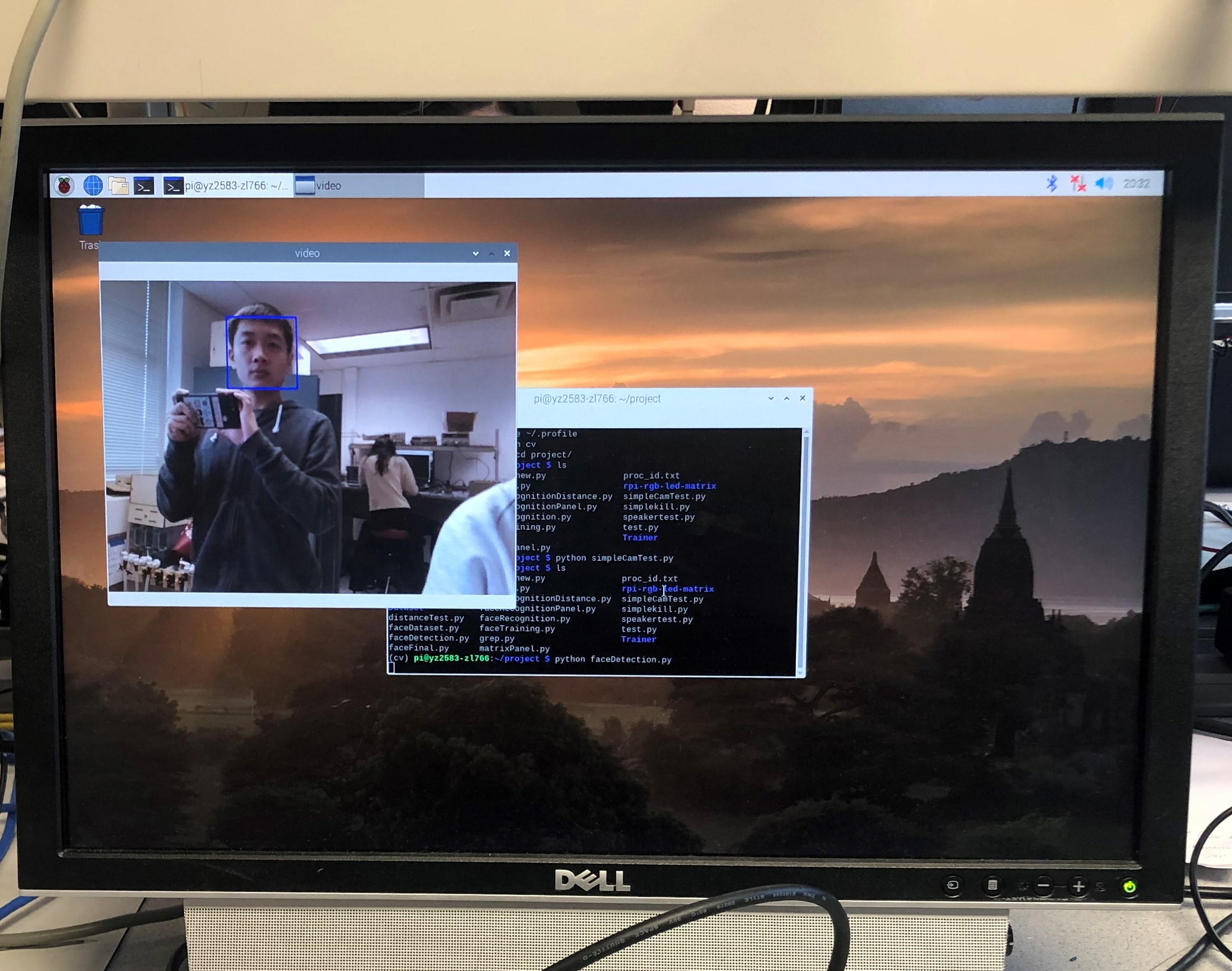
Figure 2 Facial Detection
After our system could detect faces, we needed to create a dataset to store the ID of each face and a set of grayscale images for face detection. To do so, we created a dictionary named “Dataset” and stored all samples in this dictionary.
We created a Python script named “faceDataset.py”, which can be found in our repositories. This script was highly similar to the script used in step 2 but only had a difference by adding an input command to get the ID of each face. For every captured frame, we stored it in the “Dataset” dictionary. And the name of each image file has complied with the structure “User.face_id.count.jpg”. By default, it will capture 30 samples each time the script is running, but the number can also be changed manually. Here is an example of collecting Zhaoyi's face:
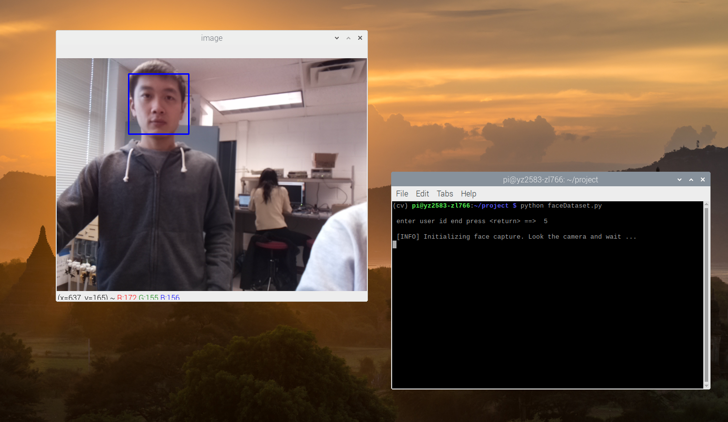
Figure 3 An Example of Collecting Data
And here is a part of our dataset:
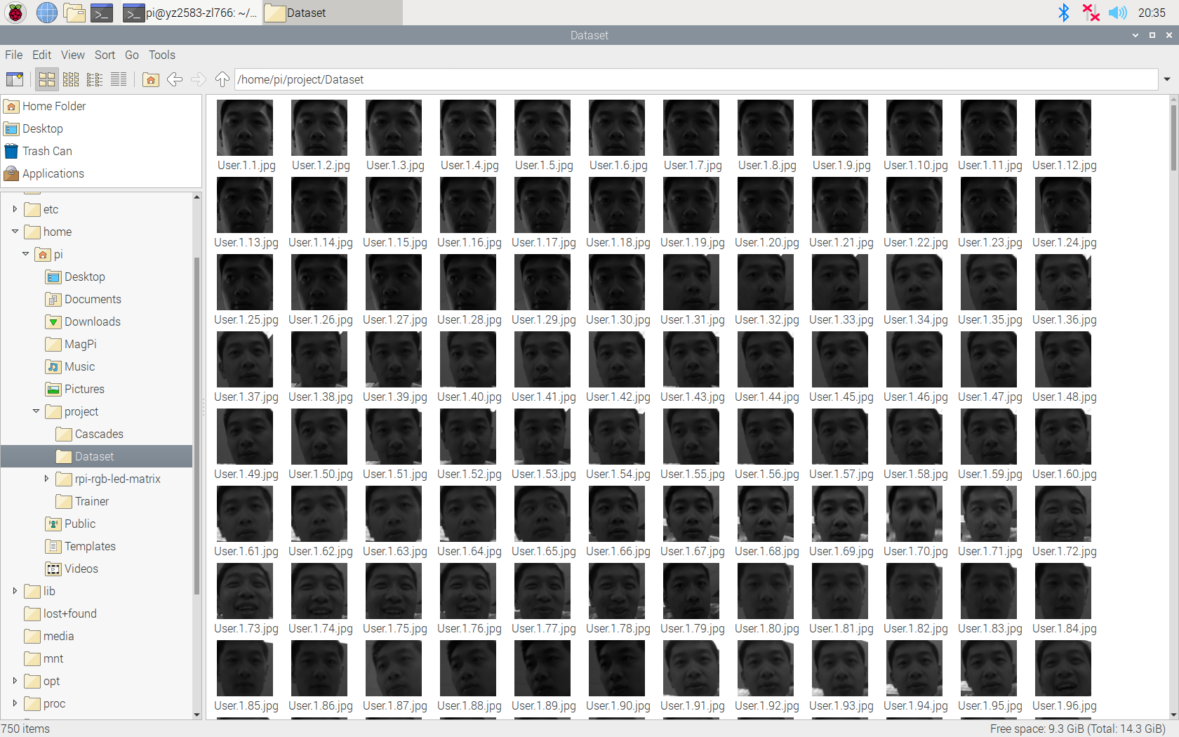
Figure 4 A Part of Our Dataset
Once we collected enough samples, we needed to extract all data to train the OpenCV recognizer. This process could be done via a specific function provided by the OpenCV library. To save the training file with the extension “.yml”, we also created a separate dictionary named “Trainer”.
We created a Python script named “faceTraining.py”, which can be found in our repositories. This script used Local Binary Patterns Histograms Face Recognizer to extract all data stored in the “Dataset” dictionary and return two arrays faceSamples and ids. This algorithm labels the pixels of an image by thresholding the neighborhood of each pixel and considers the result as a binary number. When the training process finished, a message would be printed to confirm how many faces was trained. In our project, we collected images from 3 people(Zhaoyi, Yingrong and Prof. Joe) with 210 images each person. The total of 620 images took less than 50 seconds to finish training. Here is a terminal screenshot about how it works:
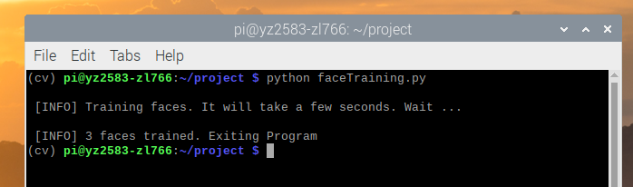
Figure 5 A Part of Our Dataset
In the last step, we created a Python script named “faceRecognition.py”, which can be found in our repositories. This script would capture a new face through the camera. And if the face had been collected and trained before, the recognizer would return the predicted ID and confidence in percentage. Here is one example of recognizing Zhaoyi with his netID and the confidence on it:

Figure 6 An Example of Facial Recognition
We used an HC-SR04 ultrasonic distance sensor (see below) to start the whole face recognition program.
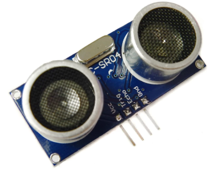
Figure 7 HC-SR04 Ultrasonic Distance Sensor from reference No.3
The HC-SR04 Ultrasonic sensor has four pins: ground (GND), Echo Pulse Output (ECHO), Trigger Pulse Input (TRIG), and 5V Power Supply (Vcc). We powered it with GPIO pin 2 on our Raspberry Pi, grounded it with the same ground of Pi, connected TRIG to GPIO pin 5 and ECHO to GPIO 6. The sensor consists of an ultrasonic transmitter, a receiver, and a control circuit inside. We control the Pi to send an input signal to TRIG and the transmitter produces an ultrasonic sound signal. The signal will reflect when hitting some objects. Then the receiver captures that bounced-off sound and sends a high (5V) signal to ECHO. That received sound will be processed by the control circuit to calculate the time difference between the signal being transmitted and received. With some simple calculations, we can get the distance between the sensor and the detected object.
We assumed that the speed of sound is 343m/s. The time difference we got from the sensor is the time to travel to one object and reflect back. So we took half of the time difference and multiplied it with the speed of sound, then we got the distance from the sensor to the object. That it Distance(cm) = 17150 * Time.
The ECHO pin outputs a 5V signal while the input pin on the Raspberry Pi GPIO is rated at 3.3V. So, we need to use a small voltage divider circuit (see below) to lower the sensor output voltage to the safe range for our Raspberry Pi.
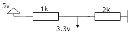
Figure 8 Voltage Divider Circuit
One example of the wiring is shown below. (GPIO choices are different from ours)
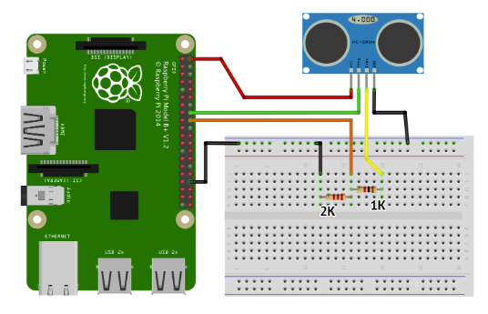
Figure 9 An Example of Wiring with the Sensor from reference No.3
This is the wiring of our project.
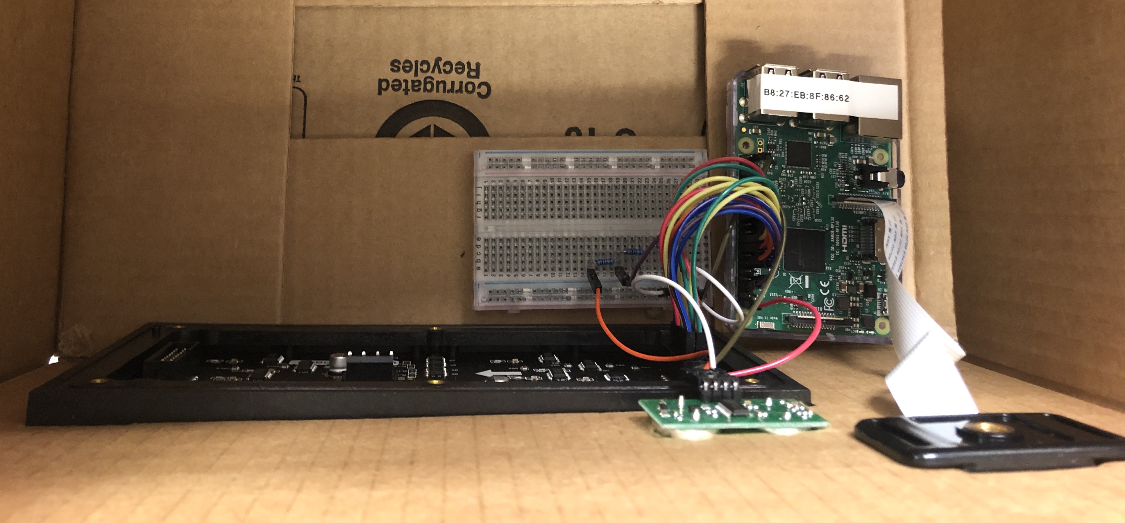
Figure 10 The Wiring of The System
In this project, we set 50cm as the threshold distance to start the face recognition and crime detection process. When anyone is within 50cm from our system, the main program will be triggered.
At first, we were trying to use a PIR proximity sensor. However, as we tested it, it was not very sensitive to objects in front of it, even though we adjusted the sensitivity and time. We tried two different PIR sensors, and neither was working perfectly. So, we switched to this ultrasonic distance sensor, which turned out to perform better.
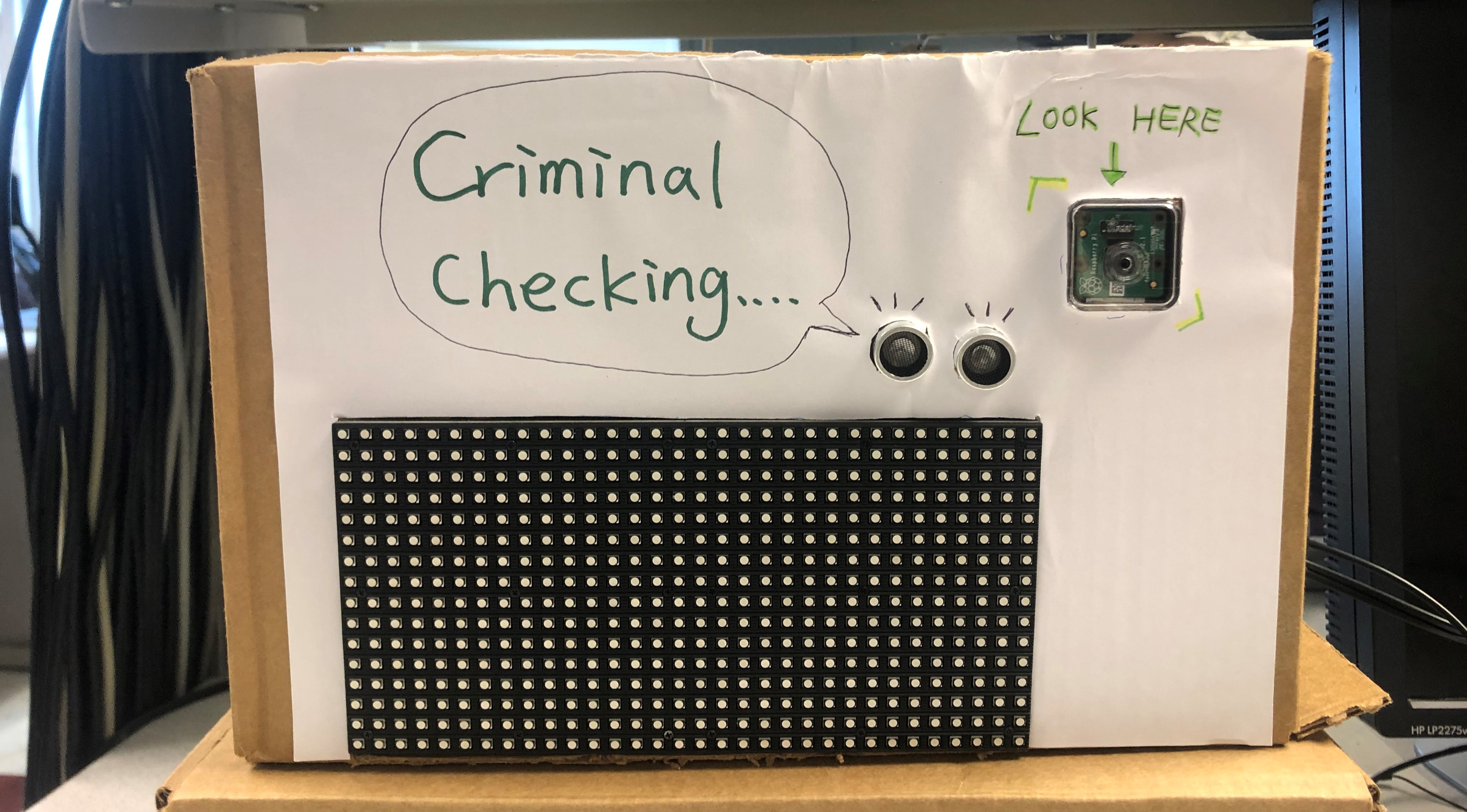
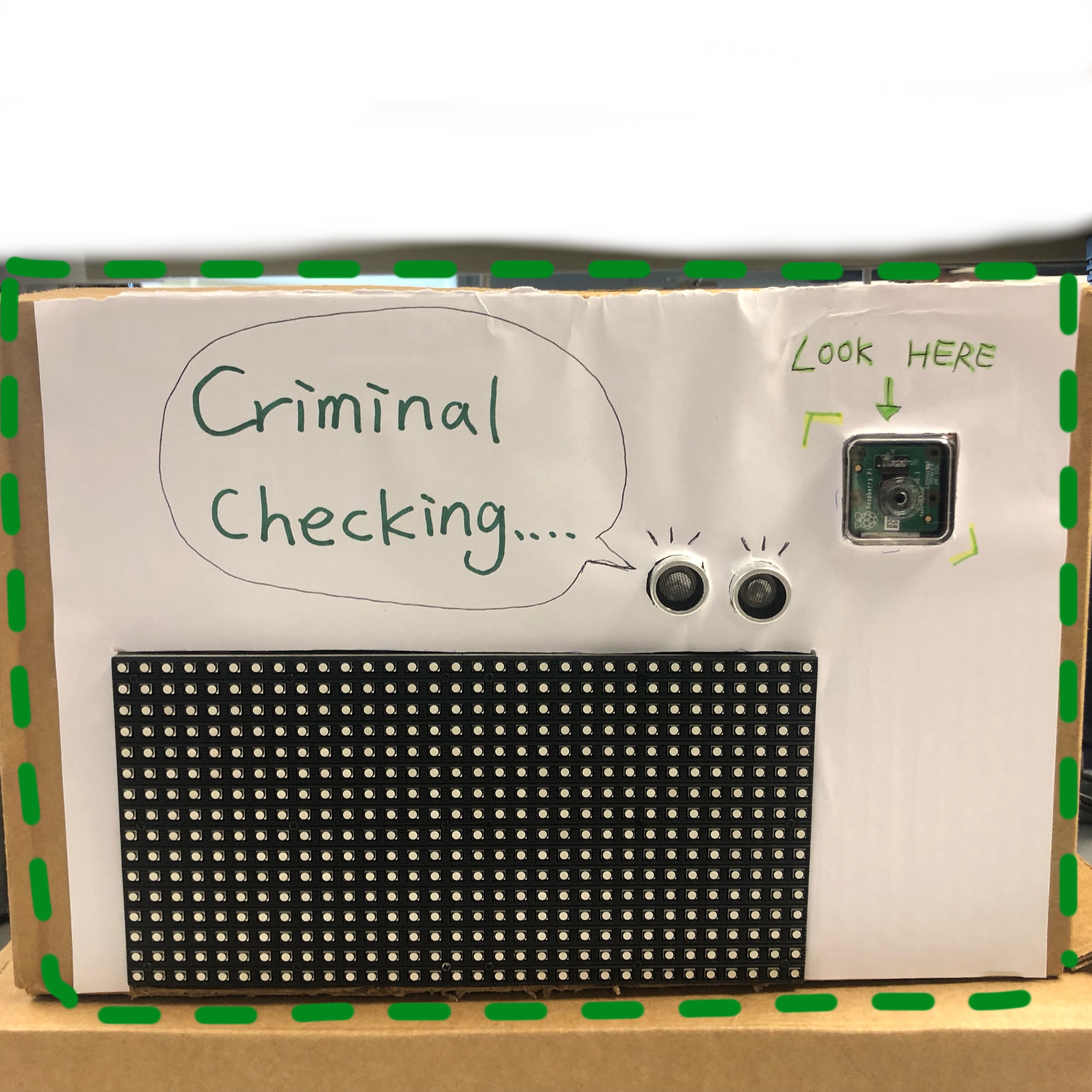
We used a 16x32 RGB LED panel to display corresponding messages when different people are recognized. Here is what a 16x32 RGB LED matrix panel looks like:
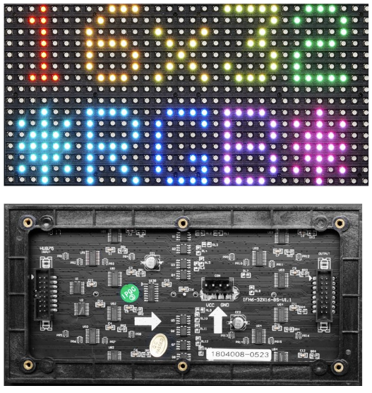
Figure 11 16x32 LED RGB Panel from reference No.4
And below is our wiring schematic diagram:
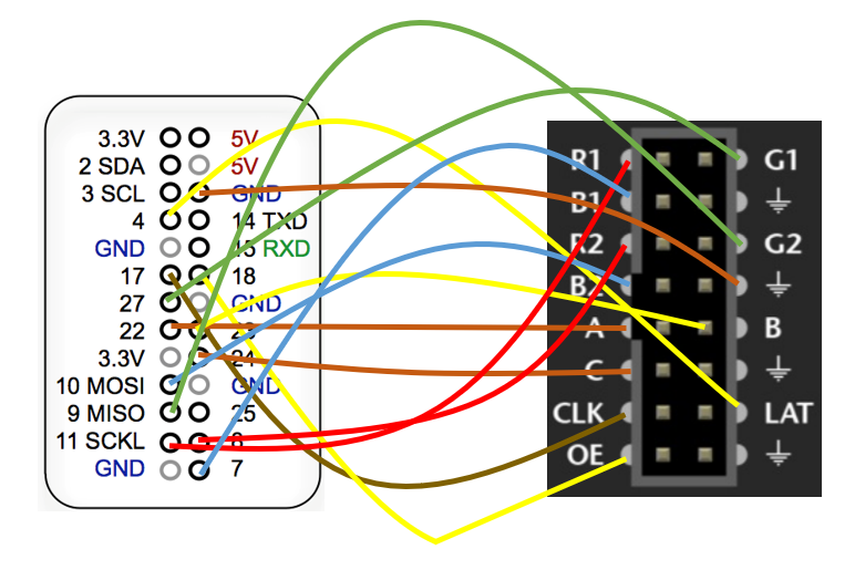
Figure 12 The Wiring of Panel and Pi
For this part of the design, we referenced a library on Mr. Henner Zeller’s Github that controls commonly available 64x64, 32x32 or 16x32 RGB LED panels with the Raspberry Pi. This library was built with C but provided Python bindings. The steps to build this were as follows:
sudo apt-get update && sudo apt-get install python3-dev python3-pillow -y
make build-python PYTHON=$(which python3)
sudo make install-python PYTHON=$(which python3)
After building, we were able to run a scrolling text on the panel with this command:
sudo python3 ./rpi-rgb-led-matrix/bindings/python/samples/image-scroller.py --led-no-hardware-pulse LED_NO_HARDWARE_PULSE -r 16
And here is a simple demo of a successfully running text on the matrix.
To change the content scrolling on this panel, we needed to change the source .ppm file. We generated three different .ppm files with GIMP, one is “Criminal Detection” in yellow, one is “Welcome~~~” in green, and the third one is “Criminal is Here!!!” in red. See these images below. More details in the following section.


Figure 13 Three Scrolling Messages
One thing we had been struggling with this library was that we couldn’t start the panel with python, but we could control it with C scripts. We have tried to change the include directories, modify the source code and double-check the wiring, but none of these solved the problem. After Prof. Joe sitting and debugging with us several times, we figured that we were working with python3 but we built this program with python2. After rebuilding it with python3, we were able to start and control the panel with python scripts as shown above.
We connected the 3.5mm jack speaker to the Pi and configured the Audio Output to “3.5mm jack” to play sound through the speaker. And we used pygame.mixer from Pygame to load, start, and stop the siren sound file we downloaded.
To facilitate the testing procedure, we chose Yingrong and Prof. Joe as “criminals”, Zhaoyi as the “citizen”, and all other people are "unknown" to the system. We planned to display the yellow “Criminal Detection”' message when no face is detected or no individual is recognized, and the green “Welcome ~~~” message when the “citizen” (i.e. Zhaoyi) is recognized. When a criminal (Prof. Joe or Yingrong) is recognized, the panel will run the red “Criminal is Here!!!” message and the speaker will beep, until the criminal is out of sight. These circumstances are called the ready status, the pass status, and the criminal status, respectively. To enter the pass status or criminal status, the predicted confidence has to be lower than 85, which means that the person looks more than 15% like somneone from the dataset. Besides, there can only be one message scrolling on the panel, to avoid the overlapping problem. Every message scrolling process is called as a subprocess. For these three processes, we defined three different commands:
CMD_0 = 'sudo python3 ./rpi-rgb-led-matrix/bindings/python/samples/image-scroller-ready.py --led-no-hardware-pulse LED_NO_HARDWARE_PULSE -r 16'
CMD_1 = 'sudo python3 ./rpi-rgb-led-matrix/bindings/python/samples/image-scroller-pass.py --led-no-hardware-pulse LED_NO_HARDWARE_PULSE -r 16'
CMD_2 = 'sudo python3 ./rpi-rgb-led-matrix/bindings/python/samples/image-scroller-criminal.py --led-no-hardware-pulse LED_NO_HARDWARE_PULSE -r 16'
The very first step of our program is to check if an object is within 50cm from the system to start the camera, as mentioned before. Once an object is detected, the panel will start scrolling the yellow “Criminal Detection” message and enter the facial recognition and crime detection part. Below is the flowchart of our program.
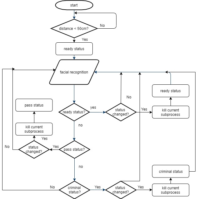
Figure 14 A Flowchart of the Whole Systyem
As the flowchart shows, if the status is changed, the current running subprocess needs to be killed and the new status can start, otherwise, there will be many texts scrolling on the panel simultaneously. Killing the right subprocess was a “painful” journey. The first method we tried was to find the process that needed to be killed and kill it. When we ran CMD_X, three processes would be launched. An example with CMD_0 is listed below.
pi 1555 1104 /bin/sh -c sudo python3 ./rpi-rgb-led-matrix/bindings/python/samples/image-scroller-ready.py --led-no-hardware-pulse LED_NO_HARDWARE_PULSE -r 16
root 1556 1555 sudo python3 ./rpi-rgb-led-matrix/bindings/python/samples/image-scroller-ready.py --led-no-hardware-pulse LED_NO_HARDWARE_PULSE -r 16
daemon 1561 1556 72 python3 ./rpi-rgb-led-matrix/bindings/python/samples/image-scroller-ready.py --led-no-hardware-pulse LED_NO_HARDWARE_PULSE -r 16
The one we wanted to kill is the daemon process, which is a grandchild process of CMD_0. We tried to get that pid with psutil, but it didn’t work. The program couldn’t import this library while we were sure we installed it. Then we started one status several times and found that the pid of the daemon process seemed to be equal to the pid of the CMD_X plus 6. We figured that since we could get the pid of CMD_X, we could plus 6 to that pid to get the pid of the daemon process and kill it. It worked fine until we were intentionally on and off the camera, one subprocess was called in the middle of another process, the “plus 6” rule was broken and everything on the panel overlapped and messed up. We also played around with different signals with the kill command, as Prof. Joe suggested. It turned out that “sudo kill -2 pid” (used for interruption) and “sudo kill -15 pid” (used for termination) were not always working, but “sudo kill -9 pid” (used forced termination) worked like a charm. So, we settled with “-9” and all we needed to do was to get the correct pid. We stuck at this issue for about one week and couldn’t solve this problem. Prof. Joe suggested that we could use the ps command to get the information of all relevant running processes, find the daemon one we want, get its pid and use “sudo kill -9 pid” to kill it. Well, we didn’t have any clue, so why not try this one. We used “ps -ef | grep samples > proc_id.txt” to get all processes relevant to “samples” (the directory of CMD_X) and write the results in a text file. Then we converted the content in that file into lists and found the process whose user was daemon and its pid. This way guaranteed to find the correct pid. And we killed that daemon process. It finally worked! The correct process was killed and the message on the panel stopped. Another thing we added was a process finish check after every subprocess call. A while loop that would stop until the subprocess call returned 0, indicating it finished, to prevent the annoying overlapping problem.
We tested every functional part as we continued to further design. And here are two pictures of the system detecting Zhaoyi and Yingrong. When Yingrong is recognized, the panel enters the criminal status and running red message on the panel. When Zhaoyi is recognized, the panel displays a green welcome message. Both are labeled with their netID and the correspoding confidence
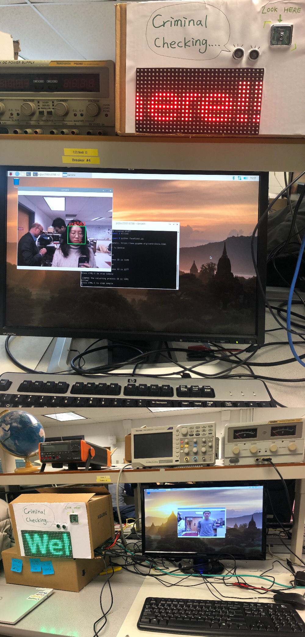
Figure 15 The System Detecting Yingrong and Zhaoyi
For this final project, we spent approximately 5 weeks working on it. We not solely achieved our expectations, but also made several improvements. With the first draft proposal handled to Prof. Joe, we just wanted to use a simple LED as the sign of our crime detection part. As the project was progressing steadily, we thought it might be a cool thing to replace the LED with the 16x32 LED matrix panel though a bunch of work would be added. Besides, to increase the complexity of our system, we used an ultrasonic distance sensor to take control of starting the main program. The results are absolutely beyond our expectations and both of us are appreciated by the results.
zl766@cornell.edu
Worked on facial detection and recognition
Tested and debugged the system

yz2583@cornell.edu
Wroked on crime detection and the panel
Tested and debugged the system
Raspbian Stretch: Install OpenCV 3 + Python on your Raspberry Pi (Adrian Rosebrock)
The official OpenCV Github repository
HC-SR04 Ultrasonic Range Sensor on the Raspberry Pi
Controlling RGB LED display with Raspberry Pi GPIO
The library for controlling RGB LED panels with Raspberry Pi
Raspberry Pi Camera Module Guideline
Since we have implemented lots of scripts, we pushed all codes and data to Zhaoyi's GitHub repository. Here is the link: Github Repository
Finally, we would like to thank Prof. Joe and all TAs for helping us all the way down here, giving us precious advice and instruction. This course has been a wonderful experience and we've learned a lot! ;)