Objective
The objective of this project is to design and assemble a robotic arm that recognizes and picks out recyclable wastes from a workspace of mixed wastes. The arm should be able to approach its target with a good accuracy, and occasional mistakes can be tolerated. This recycling robot will both reduce the cost in waste management and also reduce amount of man made wastes in nature.
Project Background
Our idea is derived from daily life experience. Every now and then, We can see people carelessly toss recyclable wastes in the non-recyclable bin. This careless behavior adds up over time and is becoming a tremendous environmental issue. According to an article by National Geographics published in 2017, abound 91% plastic is not recycled (reference 1). All those wastes are either incinerated or discarded in a landfill or nature environment. Those wastes, especially plastics, are extremely harmful to the environment. Although awareness has increased in recent years, there are still many people who are unwilling to recycle.
Therefore, how are we going to solve this problem? We introduce RecycleBot: an autonomous robotic arm that sorts recyclable and non-recyclable wastes. This system will both increase the amount of recycling and decrease the human labor cost in waste management.
Introduction
For this project, we created a model waste field on a wood board. The field contained two types of waste: recyclable and non-recyclable. To simplify the work, we limited the types of waste on this field. The recyclable wastes were represented by empty plastic milk bottles with red caps, and the non-recyclable wastes were represented by hollow white blocks. The robotic arm was set in front of the platform, and a Raspberry Pi camera was set at the top of the platform on a post. An arduino was attached on back of the post. A recycle bin was set on the left side of the platform.
When the system first started, the Raspberry Pi camera captured an image of the field. Then the system checked if there were recyclable bottles in the field by identifying red circles on the image with a OpenCV program. If there was one or more bottles, the program would calculate the center of the red caps. Then those values in pixels were converted to values in meters. Another program read the location values and converted them to sets of angles using inverse kinematics. Each set contained six angles since there were six servos on the arm. Then the Raspberry Pi would send those angles one by one to an arduino that controlled the arm through USB serial port. Next the arduino send the angle movements to the servos on the arm through serial port. The arm would then perform a series of movements that allowed it to grab the bottles at the target locations and put them inside the recycle bin. After all bottles were cleared, the arduino would send a ‘done’ message to the Raspberry Pi, and the Pi would take another image of the field. The whole process described above is then repeated.
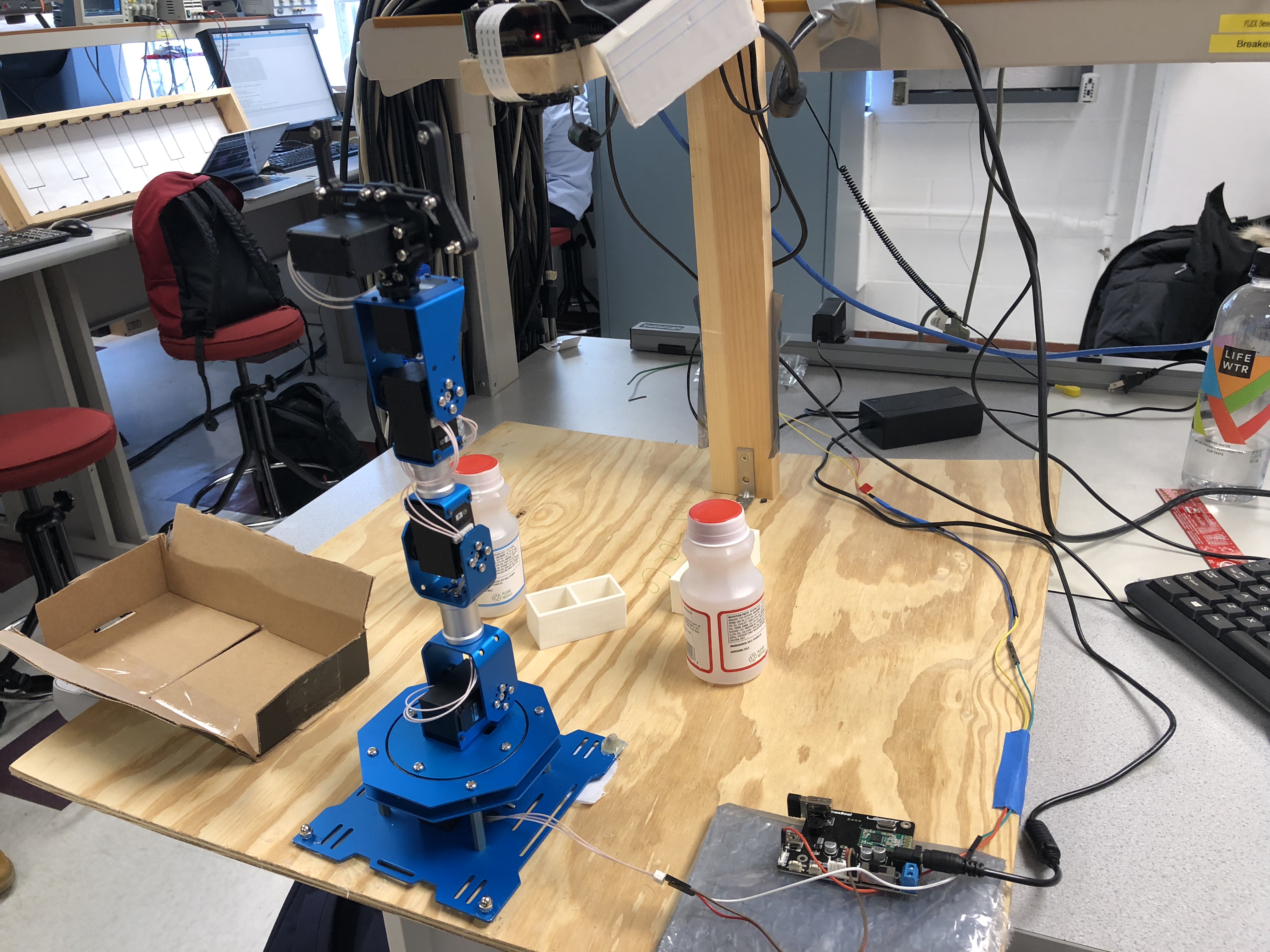
Figure1 Note: This image shows the final and complete system of this project.
Design
Hardware Design
In the first week of final project, we planned our work and prepared for hardware and software simultaneously. Because we were familiar with lab servos, we wanted to 3D print all the necessary mechanical parts for our robot.
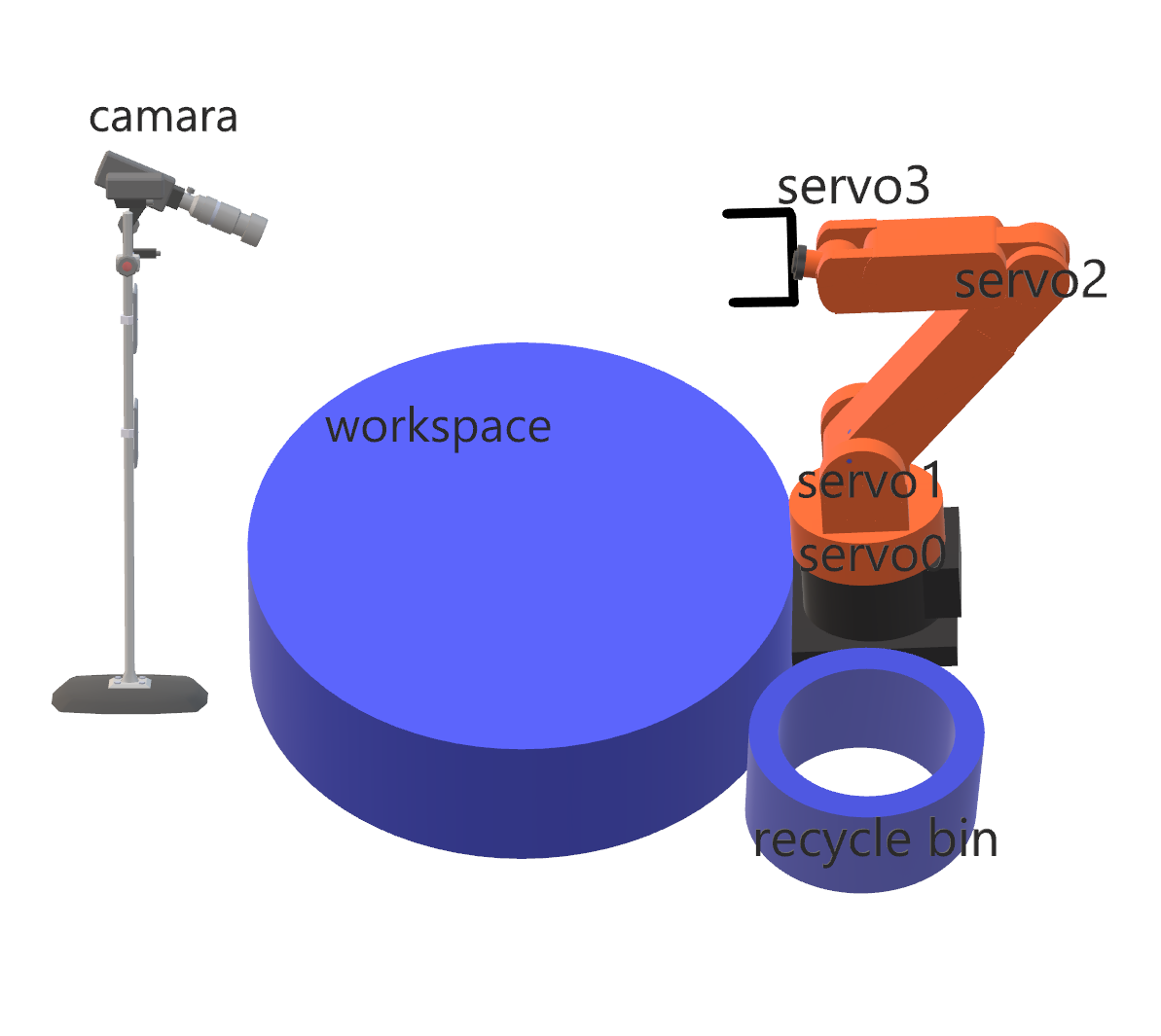
Figure2 Note: This is the first design sketch we made. This sketch describes most of our system parts. The initial design includes four servos and one camera.
We first downloaded an open source robotic arm CAD from online. We printed several parts but got some printing failures for the larger parts. Additionally, some parts required up to 20 hours to print. There were 27 parts in total which we estimated would require at least a week to print. We gave up for printing the whole arm due to time limits.
We then bought a robotic arm from Amazon.com, we decided to use only the mechanical parts of it. Because the servos we used in lab and the servos for the arm were of different sizes, we 3D printed links and brackets that would fit our own servos.
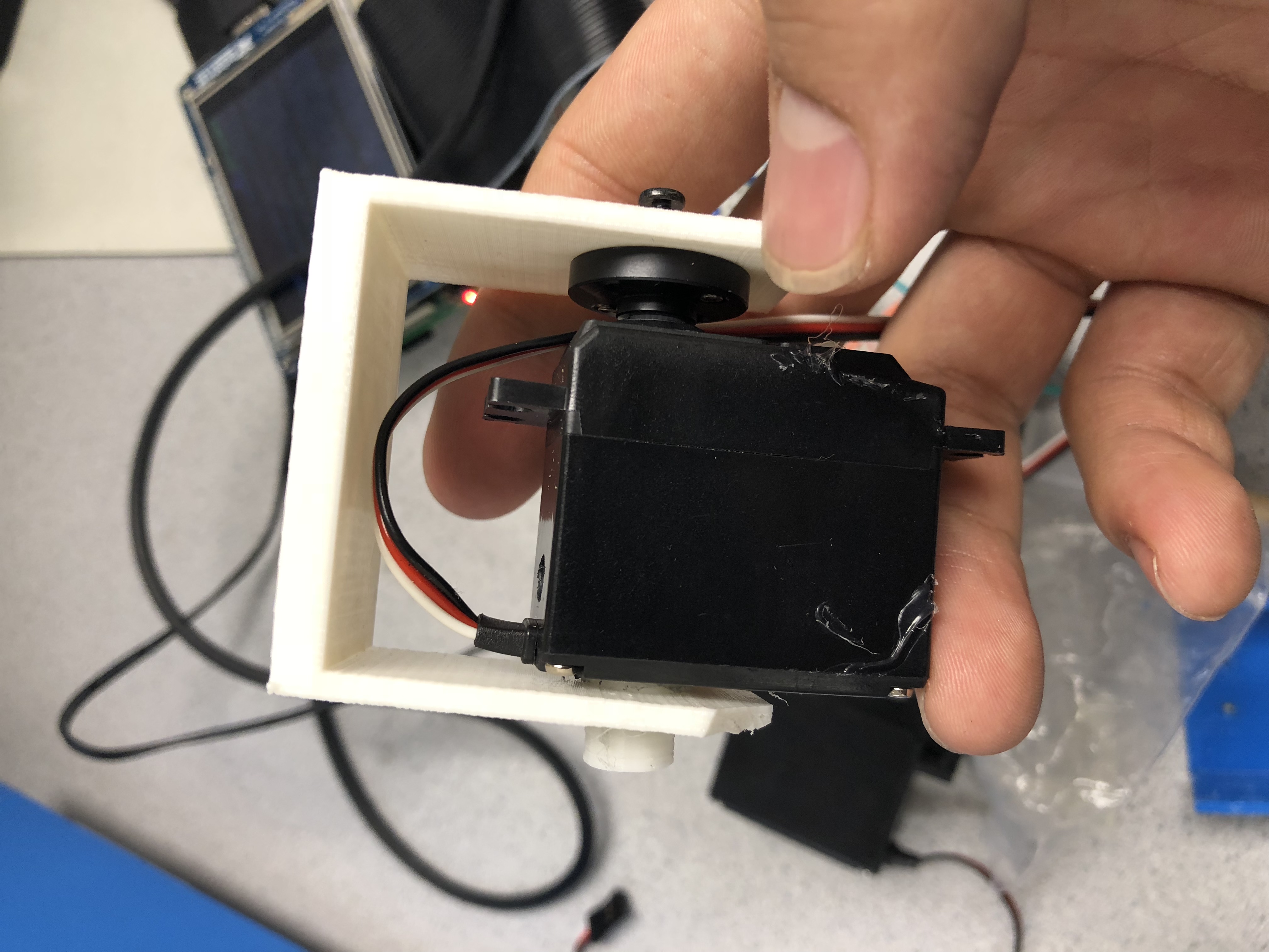
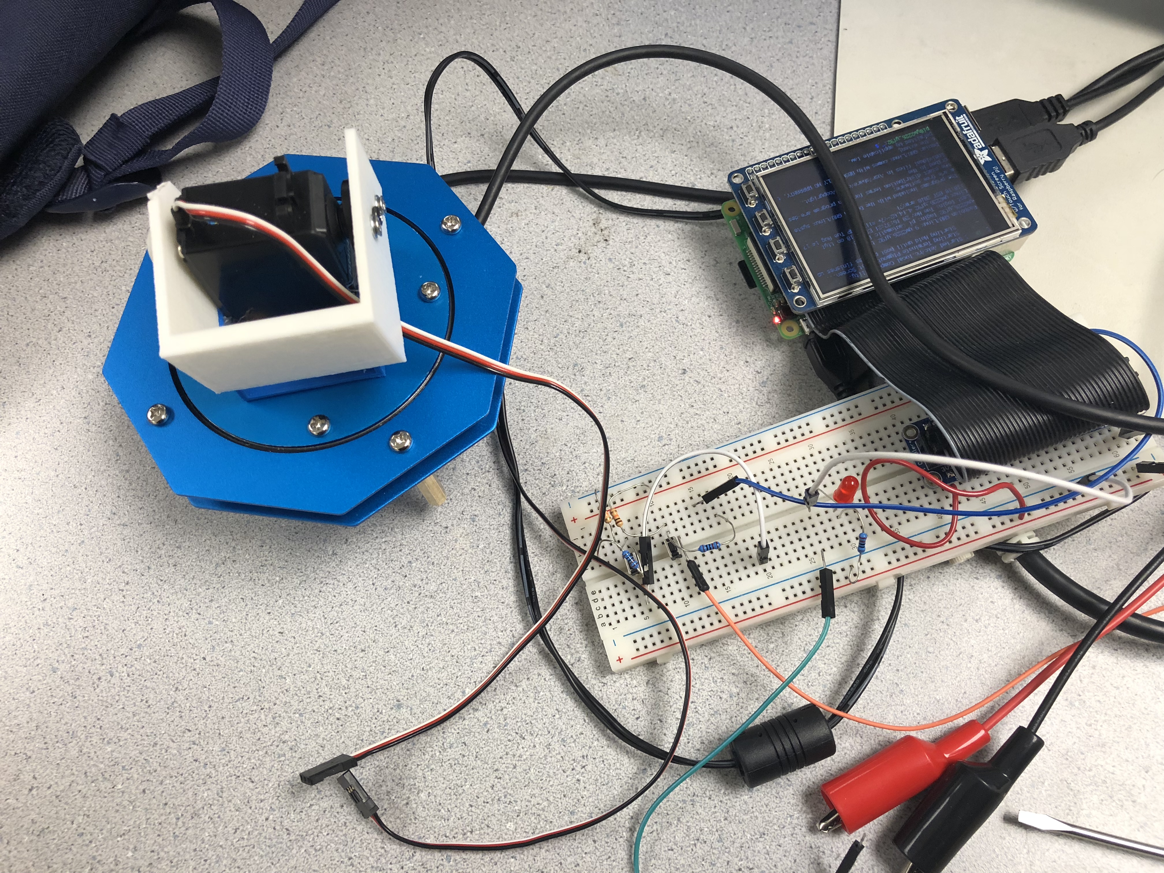
Figure3 Note: We initially want to 3D print all parts that are related to the servo and combine them with other frameworks such as the base station and the gripper. However, the PWM servos are not as accurate as the serial bus servos so we give up this plan.
Then we faced the biggest issue: the PWM lab servos were not accurate. When the signal was send through PWM, the error could be over 5 degrees. Therefore, they were too incurrate to be used as servos for robotic arm. We had to give up the old servos and use the servos from the arm kit instead.
We attached all the servos and links using robotic arm we bought online. After testing the functionality of every servo and link, we built our whole system as the following image shown.
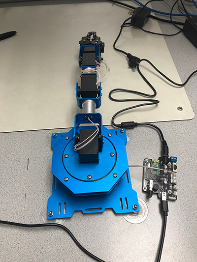
Figure4 Note: The LewanSoul xArm kit comes with mechanical parts, servos, a motor controller, desktop software, and many more accessories. We are using their mechanical parts and servos. During the testing, we are using the motor controller as a power supply switch for the arm.
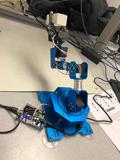
Figure5 Note: We accidentally broke the motor controller that the arm kit originally contained. So we instead connected the signal wires on the servos to the serial port on an old Arduino. The servos followed the signals from the Arduino very well.
Software Design
Computer Vision
The first task of this system was to take an image of the waste field and identify the bottles on the field. We assembled a wooden post/framework and attached a Pi camera on it so that the camera was directly above the field. The camera was attached to a Raspberry Pi, and the Pi sat above the post. In the beginning, the camera took an image of the field and stored this image inside the Pi’s file system. We wrote a C++ program that used OpenCV to detect any red circles in the image. The OpenCV part of our program was referenced and modified from the blog Solarian Programmer (reference 2). This program first converted the image from RGB color space to HSV space so that it can easily select a single color based on its hue. Then OpenCV threshold the image and only kept the pixels that were red from both the lower (0-10) and upper (160-179) HSV hue range. The resulting images that contain only the red pixels were then combined and blurred. Next the program performed a Hough transform using the OpenCV HoughCircles function to detect the circles. All circles were then stored in a vector as objects with center and size so we could easily locate them.
We tested this program multiple times and it almost always worked as expected. The only mistake that the program made was that sometimes it recognized very small circles around the bottle neck. This happened rarely, and the amount of additional circles was not large. When this happened, the arm would try to grab at the same spot multiple times. We thought this was tolerable. However, the program performed very poorly when there were interferences, such as when the lighting was dim or when there were interferences in the field, especially other red objects, the program behaved very poorly. It could recognize up to hundreds of additional noises and the arm would get out of control, trying to grab non-existent objects.
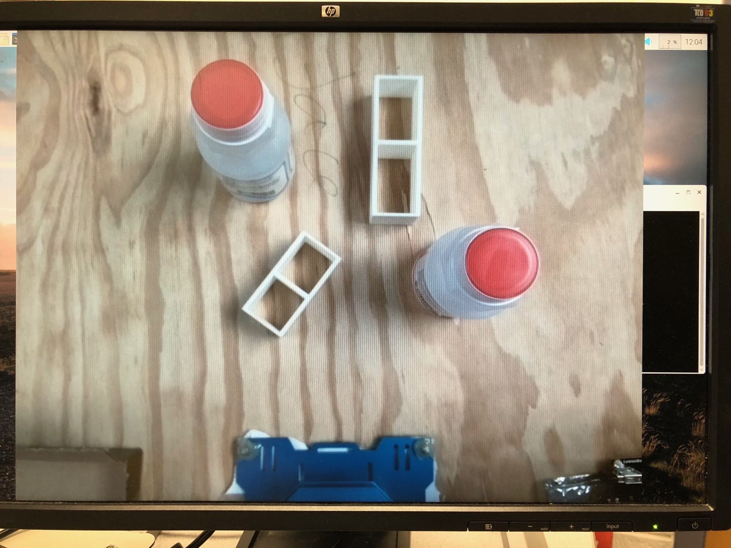
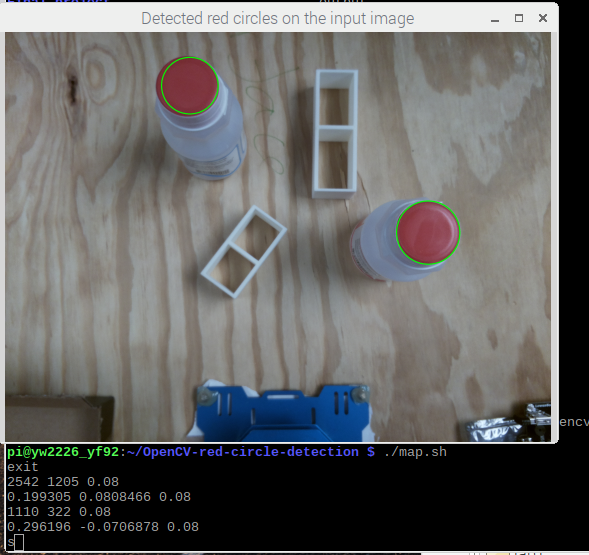
Figure6 Note: The Pi camera takes a picture of the workspace (left) and saves the image in the RPi3 file system. Then the image recognition C++ program identifies the red circles. The identified cycles are outlined in green, and the center locations are printed for testing purposes (right).
Coordinate Conversion
The circles’ location calculated by OpenCV were in units of pixels, so we had to convert them to actual distances in meters. There were many ways to do this, such as external packages. Since our platform was not flat and the image was not a perfect projection of the actual platform, we thought the best way was to take some sample points and measure the backward projection. So we first found out the maximum range that the arm could reach, which was 0.15 m to -0.15 m in y (horizontal) direction and 0 m to 0.3 m in x (vertical) direction. Then we moved the arm to the two diagonal corners and placed the bottles in the place where the arm could grab. Next we took an image of the field and calculated the pixel position of the bottle’s center. Now we have two set of (x, y) points, one in meter and one in the corresponding pixels. We found the slope and y intercept for both x and y direction, and wrote a simple linear conversion function. finally, we converted the bottles’ centers from pixel to meter with this function and stored them in a text file.
From what we saw in the end result, this simple linear conversion was very accurate in most cases. It was most accurate when the bottle was close to the center of the field (where the camera was placed) and less accurate further away. This was mostly because the wooden field was not flat, and the image of the camera was also not a perfect linear projection. A way to improve its accuracy was to sample more points and make a 2D interpolation using methods such as basis spline. Due to time limit, we settled with linear conversion.
Inverse Kinematics
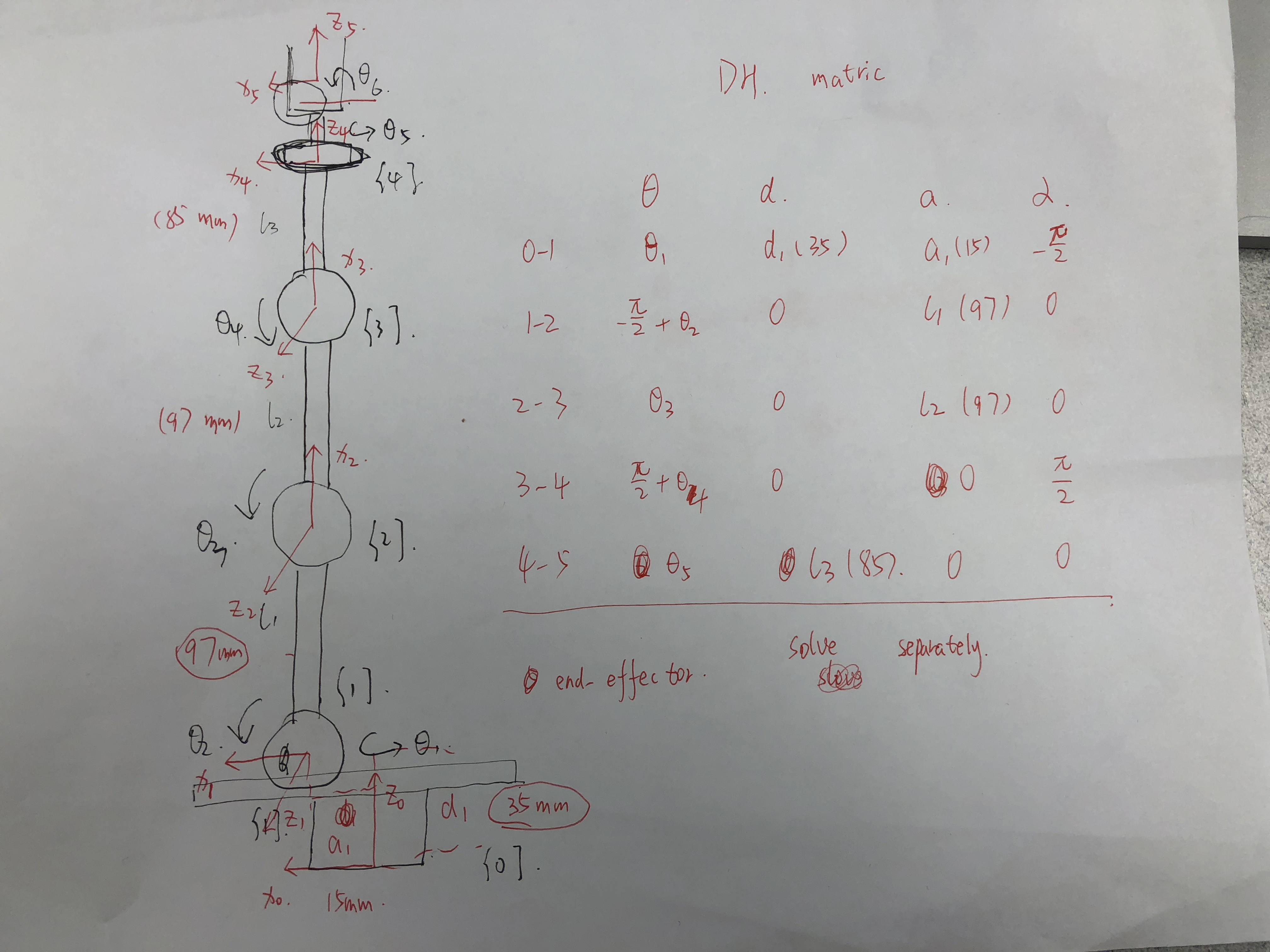
Figure7 Note: On the left, we build different frames on each servo. On the right, we list four parameters for frame change. This aims to compute Forward Kinematics.
The second task of this system was to convert the target location in meters to servo rotating degrees in angles. We used Inverse Kinematics to achieve this task. Before we dive into Inverse Kinematics, we should briefly introduce Forward Kinematics. Suppose we know the rotating angles of our 6 servos, we could build a reference frame for every servo. Forward Kinematics is to build a position relationship of base attached servo with end-effector, also known as a gripper. The basic method for Inverse Kinematics is initializing a rotating angle for each servo and then use Forward Kinematics to compute the current target position. We compare current target position and goal position to output an error. Then Velocity Kinematics aims to calculate the updated rotating angles (you could image Velocity Kinematics as gradient since we want to minimize error). Then in the iteration, we minimize error to a threshold and output rotating angles for each servo.
We used open-loop control which meant the arm would reach the target with a single calculation. Although this was not as accurate as close-loop control, it was faster. Considering that both image recognition and serial communication were slow, we chose open-loop control. The test result showed that this method was fairly good in terms of speed and accuracy. On the simple model platform that we build, our robot could successfully recognize and pick up bottles over 95% of the time unless the bottle is out of the arm’s reach. Additionally, we used Forward Kinematics to test the accuracy of Inverse Kinematics, and the results were satisfactory.
Communication between Raspberry Pi 3 and Arduino
We used Serial Port to make Raspberry Pi 3 communicate to arduino. There were six values to be sent for each target location, one angle for each servo. Because the arduino had only one serial port, and it needed to communicate to both the RPi3 and the servos, we set up a new hardware serial on pin 10. To ensure everything was sent successfully and in order, we set up a simple protocol for the RPi3 and arduino to communicate back and forth. The arduino first send a ‘ready’ message to RPi3. Then RPi3 send the first value, and arduino had to confirm that it received this message by sending this value back to RPi3. When all six values were sent, arduino would sent a ‘done’ to RPi3. If there were more red bottles on the work space, RPi3 would be ready to send the next location. Otherwise, RPi3 python program would exit and the camera would take a new image of the platform to be processed.
Control 6 servos by Arduino
We used Software Serial Port on Arduino to control the 6 different servos. The basic rule was to restrict the rotating limits for every servo first. The rotation range was between 0 ~ 240 degrees. The minimum increment or accuracy for each servo was 0.24 radian. Each servo had a unique ID number and we could identify them by this number. In addition, we could control their rotating duration and rotating position. In the Arduino code, we pre-defined several functions like move_to_initial(), move_to() and move_to_bin(). They represent move to the vertical initial position, move to target location based on input arguments and move to bin location, respectively. During the testing, we did not face any problem with serial communication or servo control.
Results
We reached our basic goals, and every subsystem performed well as expected. Our computer vision program recognized the red caps on the bottle with good accuracy. The coordinate conversion, although very simple, also performed very well within certain ranges of distances. Finally, our Inverse Kinematics algorithm was sturdy and very rarely failed unless the bottles were placed in unreachable places. The overall accuracy was over 95%. The bash script we wrote realized the whole process in a single command. In general, the whole process was very smooth, and we were very satisfied with the end product.
Our minimum demo goal was to have the robotic arm touch the bottle. We achieved this goal and beyond. Our final system was able to grab the bottle and put it aside with a good success rate.
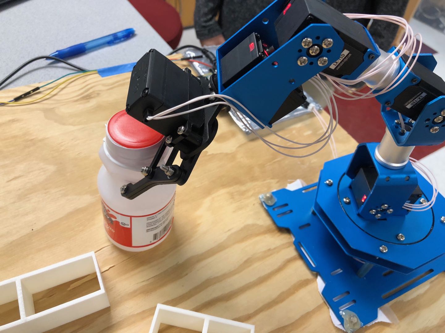
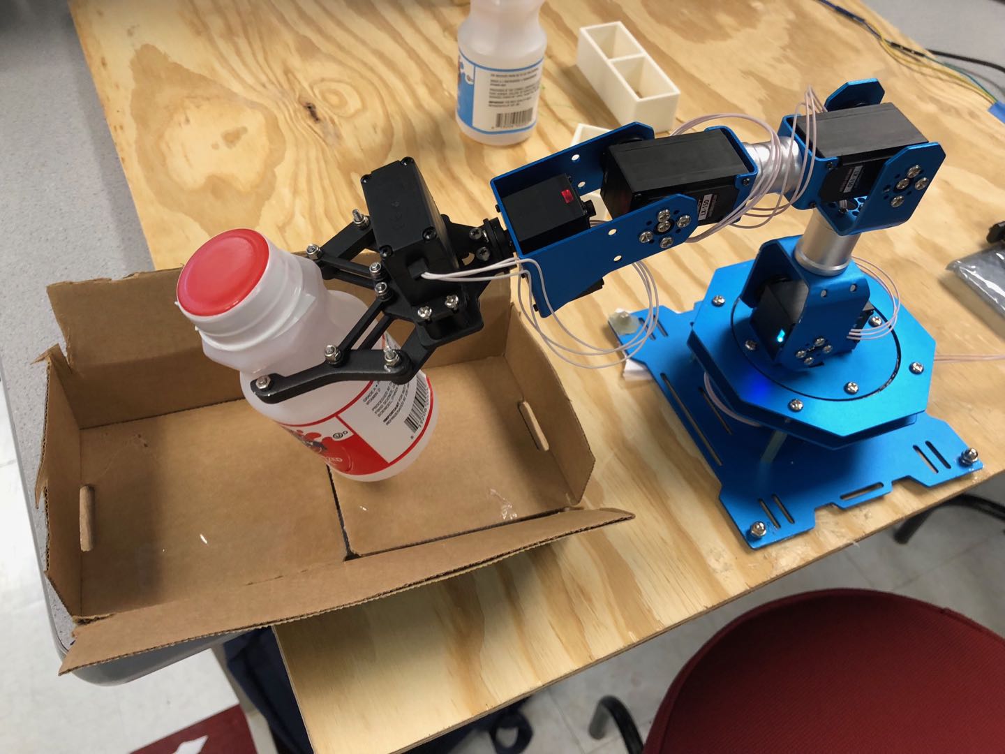
Figure8 Note: Those two image demonstrate how RecycleBot successfully identifies a bottle, grabs it at the target location, and puts it inside the recycle bin.
Conclusion
The test results that our system achieved were fairly good in terms of speed and accuracy. On the simple model platform that we build, our robot could successfully recognize and pick up bottles over 95% of the time. There were some situations when the robot performed poorly, such as when the light was dim and when there were other red objects on the platform. One thing we discovered is that it is impossible for the robot to be accurate 100% of the time. During the entire process, there were many places that could be heavily affected by noises and uncertainties, such as the image recognition stage, the inverse kinematic calculation, and so on.
Future Work
Our project has tremendous potential and many more additional features to be realized. There are two major directions of possible improvements. One is to make the model more realistic. This can be achieved by adding a more complete set of trash to our field space. Another direction is to make the system more accurate. This can be achieved by changing the control from open-loop to close-loop.
In this project, we used milk bottles to represent recyclable wastes and white blocks to represent everything else. We also set our target position height to be constant, so the robot can only grab bottles that are standing up straight. To make this model more realistic, we can use a more complex machine learning program to recognize all types of recyclable wastes, such as other types of bottles, plastic bags, or even paper boxes. We also need the system to recognize those wastes in all directions, instead of just from the top view. To achieve this, we need to add more than one camera to also detect object’s height.
With a more complex set of objects to grab, open-loop control will not be accurate enough. We need to change the picking up angles depending on the current location of end-effector and target location, orientation and shape. This change will be very complicated, corresponding solutions will be based on issues and how current industrial and research are handing them.
One more idea is proposed by Professor Joseph Skovira, we could change our fixed workspace to a conveyor belt. Robotic arm would pick up recyclable wastes sequencely. To realize this change, we need to make our system a real timed system. Computation complex and system working speed should be considered and improved.
Work Distribution
Team work: testing, final report
Yanrui Wang: mechanical assembly, Inverse Kinematics, arm control
Yazhi Fan: OpenCV, coordinate conversion, serial communication
Project Parts
| Part Name | Price (USD) |
|---|---|
| LewanSoul LX-16A Serial Bus Servo | 14.99 x 5 = 74.95 |
| LewanSoul arm mechanical parts | 5 |
| Raspberry Pi Camera Module V2-8 Megapixel | 20 |
| old Arduino | 0 |
| RPi3 (provided) | 0 |
| scrap wood | 0 |
| total | 99.95 (There are 6 servos on the arm but one is not in use, its value is always 0) |
Code Appendix
| Purpose | File Name |
|---|---|
| Image recognition | circle_detect.cpp |
| Inverse Kinematics | final_code.py, IK.py, FK.py, VK.py |
| Servo control | ServoRotation.ino |
| bash script for running everything autonomously | arm.sh, arm_infinite.sh |
Download is avaliable on the top of the web page
References
Thanks to Angus Gibbs (aag233) and Joao Pedro Carvao (jc2697) for giving us permission to use their web page design as a template.
Thanks to Professor Joseph Skovira and TAs for giving us advice and help.
- https://news.nationalgeographic.com/2017/07/plastic-produced-recycling-waste-ocean-trash-debris-environment/
- https://www.thingiverse.com/thing:1693444
- https://solarianprogrammer.com/2015/05/08/detect-red-circles-image-using-opencv/
- https://rpal.cs.cornell.edu/foundations/kinematics.pdf#section.3.8
- https://courses.ece.cornell.edu/ece5990/ECE5725_Spring2018_Projects/aag233_jc2697/index.html#design
- https://www.sunfounder.com/blog/rpi-ard/
- https://www.w3schools.com/html/