Telepresence Vehicle
Motion controlled vehicle with a camera!
A Project By Xiaoyu Yan (xy97) and Ji Wu (jw2473)
Demonstration Video
Introduction
For our final project, we build a vehicle system that can be controlled remotely as long as there is
wifi. The vehicle has a built in camera that transmits the video feed to the user at a base station.
The user uses motion control from the base station to remotely control the vehicle. This project was
inspired by remote control drones and vehicles. We wanted a way to remotely control a vehicle when
users don’t have sight of the vehicle. As a result of this project, we were able to have a controller communicate with the vehicle by
exchanging IP addresses for requests over wifi. The controller contains a sensor that captures motion data for vehicle control
and then sends that data to the robot using socket UDP and wifi. The vehicle then receives commands transmitted from the
controller and move accordingly. The user can see through the vehicle with an onboard camera that host a video stream using wifi.
The stream is displayed on the controller in a user friendly way using Pygame. The system is robust enough to work with dynamic
IP addresses given that the controller and robot both connect to the same wifi and already recognized the wifi. The video
stream can reconnect if wifi connection is temporarily broken. Due to its reliability on wifi to function, this vehicle can only
be used in locations with wifi connection, which is likely indoors.
We enjoyed working with the technology involved in working on a remote controlled vehicle from the ground
up. The concept for this project isn’t anything new; remote control
vehicles and drones are already used today with radio control and onboard camera that connects to wifi.
The uses of these devices are for exploration of environments too hostile or inaccessible to humans
which involve both scientific and military explorations. While the development of autonomous vehicles
is ongoing and their reliability is increasing every year, remote control vehicles can still find
use today with a human in control for complicated or important tasks, especially if real time control
is possible. This also avoids vehicle ethics which is another huge topic. This system can have practical uses in helping disabled
people to engage in
physical tasks remotely which can help increase employment of disabled people.
Project Objectives:
- Get motion reading from accelerometer and send reading to another Raspberry Pi.
- Move vehicle according to accelerometer controls
- Send camera images from one Raspberry Pi to another with minimal latency.
- Implement a vehicle system that supports robust remote control and requires limited user setup.
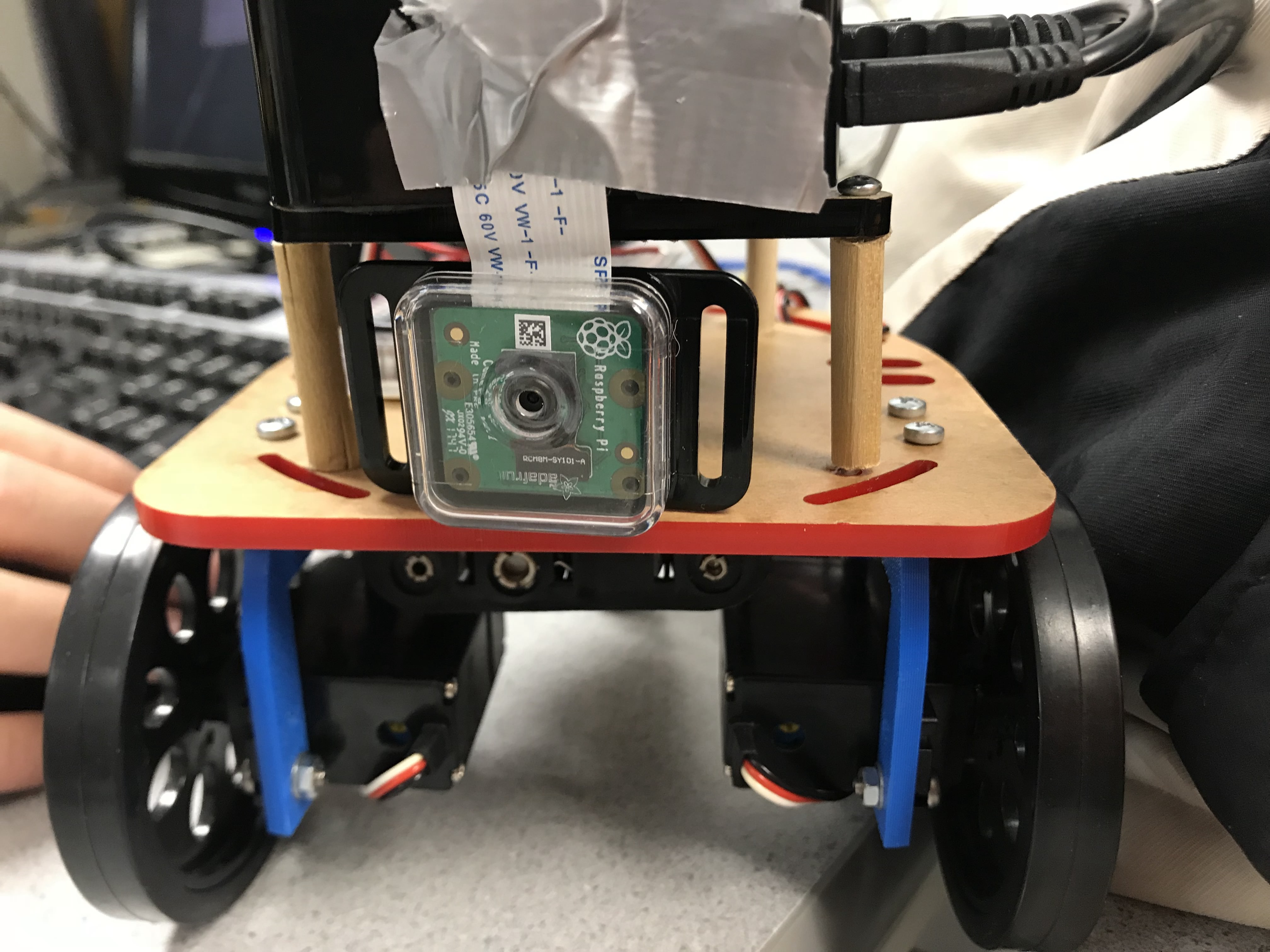
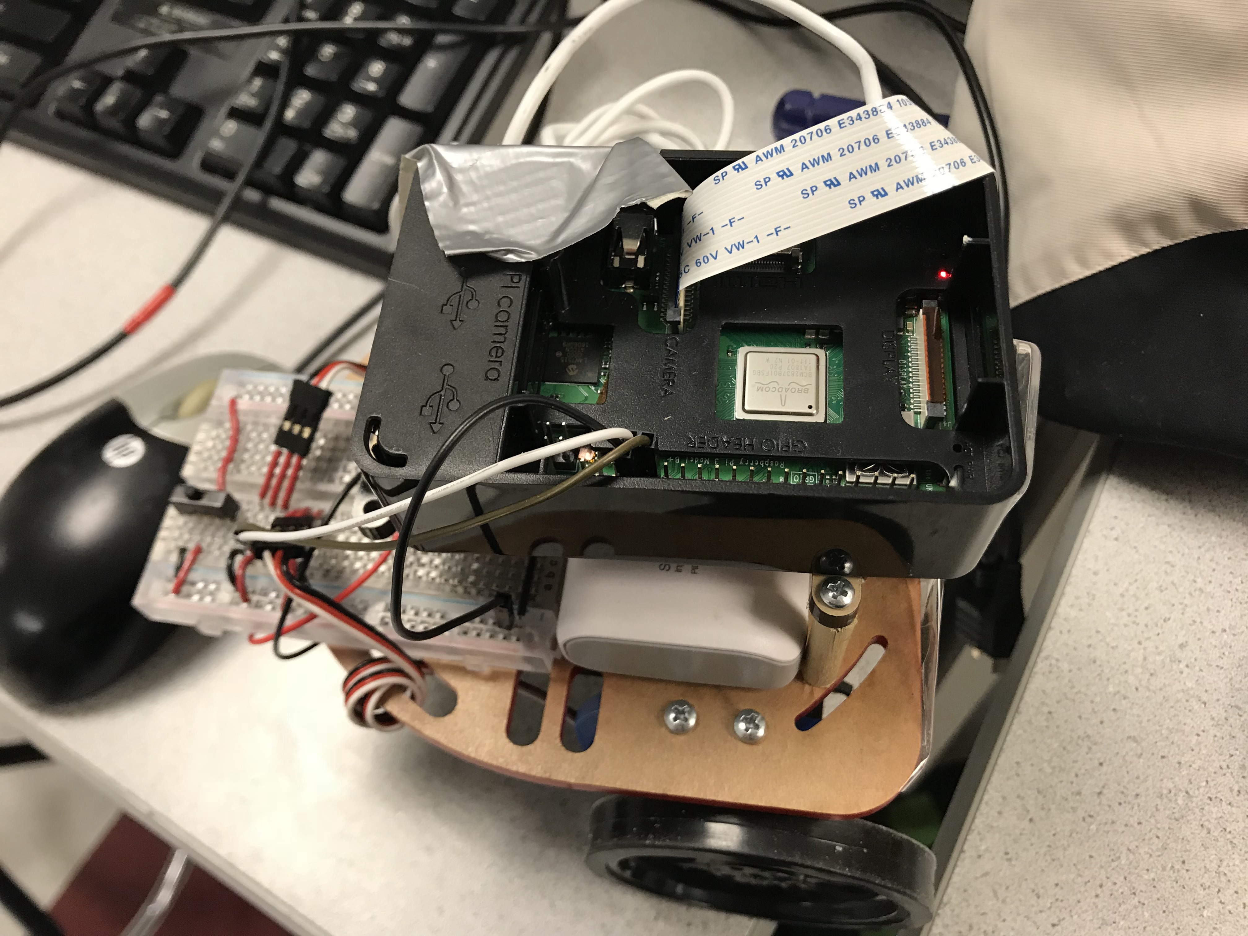
Project Setup
For this project, we used two Raspberry Pi 3B’s (RPi). One for the remote controller otherwise known as the base station and the other on the vehicle that serves as the vehicle “brain”. The project also requires additional peripherals such as:
- RPi camera V2
- Built-in bluetooth
- BNO055 Absolute Orientation sensor
- Onboard wifi
- PWM servos
The coding language for this project is Python 3.5.
Before any project, make sure that the RPi is updated by running.
Sudo apt-get update

  Sudo apt-get upgrade
This project was done on the Raspbian Linux Stretch version. However, the linux kernel updates constantly and the current version will change over time.
The RPi camera library support can be downloaded using:
sudo apt-get install python-picamera python3-picamera
We also want to enable the Picamera by using sudo raspi-config and enabling the Picamera in the settings.
To use the bluetooth on the RPi, we used the Blue Dot library handle communication between two RPi 3’s with built in bluetooth. They can be installed by entering:
sudo apt install python3-dbus
sudo pip3 install bluedot
We also made extensive use of RPI.GPIO library to generate PWM signals to control the servos and to receive input from buttons on the PiTFT. The can be installed using:
pip install RPi.GPIO
or
sudo apt-get install python-rpi.gpio python3-rpi.gpio
The base station use Pygame to display camera feed. Pygame should already be installed on the RPi
To process the camera images and compress it on the server, we used opencv and numpy.
These libraries are also used to decode the camera feed on the receiving end and manipulate the feed.
They can be installed using:
pip install opencv-python
or
sudo apt-get install libopencv-dev python-opencv
We used serial communications for sending data between the base station and the sensor.
We therefore must enable RPi’s serial interface by once again going to raspi-config.
In the same location, we also disabled console login using serial to prevent it from conflicting with our serial device.
Next we install the BNO055 Adafruit library by using:
cd ~

git clone https://github.com/adafruit/Adafruit_Python_BNO055.git

cd Adafruit_Python_BNO055

sudo python setup.py install
This library greatly sped up our development with the BNO055 sensor and data gathering.
Design
Bluetooth IP Address Exchange
Initially, we expected to have a static IP for the controller so we can simply handle the requests from the controller side. However, sending packets to a specific public address is not permitted by the network of the college, so we turn to setting up all metadata over bluetooth when rebooting. Additionally, using wifi means that IP address can change per connection to said wifi which means that IP address from connection on one day may be different from connection on the next day. Thus, to avoid hardcoding the IP address of the RPI’s everytime we turn them on, we must explore ways to use any permanent properties of the RPi’s.
Enter bluetooth and MAC address! Each RPi comes with a permanent MAC address that we can use!
The Raspberry Pi 3b conveniently contains built in bluetooth which we can use to communicate between to RPi’s and send a string containing the IP address. To make this happen, we used the Python Blue Dot library. First we must pair the two RPi’s. This can be done in several ways: one way is using the bluetooth controller by running bluetoothtcl on the terminal and running discoverable on. The controller gives us the MAC address of the RPi we are using which we can use on the other RPi to pair. This can be done using connect mac address to pair the devices. One can use paired-devices to check if the pairing is successful.
Once the pairing is done, we can test if bluetooth works with sending a string using BluetoothServer and BluetoothClient classes. These classes use RFCOMM serial to send data to a server. We originally tried to use this communication method by using pyserial and then socket for bluetooth communication before we discovered this library which did what we envisioned.
To send IP’s, we first used Python’s subprocess library to send and record terminal commands to the RPi and then save the IP as a string. To get IP address, we used hostname -I. To get MAC address, we used hcitool dev | grep hci0, where hci0 is our bluetooth device. The Blue Dot library allows us to set up a client connecting to the specific MAC address of the server. This part is hardcoded where we ran the above command and obtained the MAC address. The vehicle will then attempt a connection to the server hosted by the base station and repeatedly send its IP address until it receives a response from the server. The response is the base station’s IP address. This is a blocking function where the system will not continue until messages are exchanged. Currently, we did not implement error checking so the bluetooth will unblock if any message is exchanged.
This was a great solution suggested by our professor to get around the non static IP problem with wifi. Not needed to find IP and manually enter it for both the vehicle and base station means less maintenance on the user’s side to get this system started. Once the bluetooth is connected and IP addresses exchanged, we can completely shut off bluetooth and utilize wifi to send data between two RPi’s.
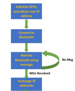
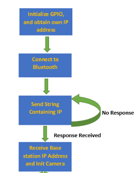
Above contains the state diagrams for bluetooth and IP exchange. If no response or messages, both systems block and wait until messages recieved. The base station will get the message first and then send the response.
We also added a little GUI to show that the system is attempting to swap IP addresses. This helps user experience and allows us to see if the device is blocking on the bluetooth.
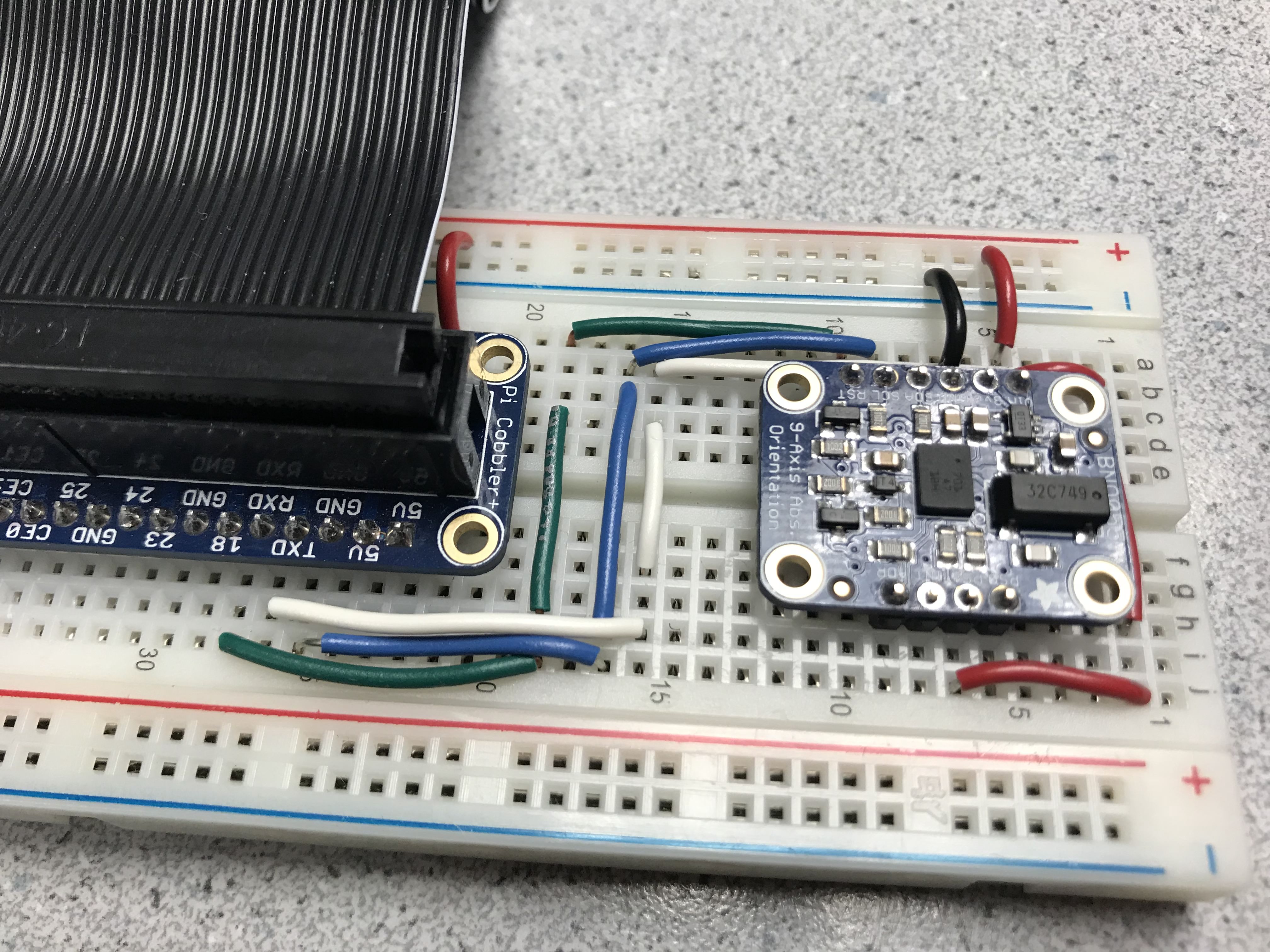
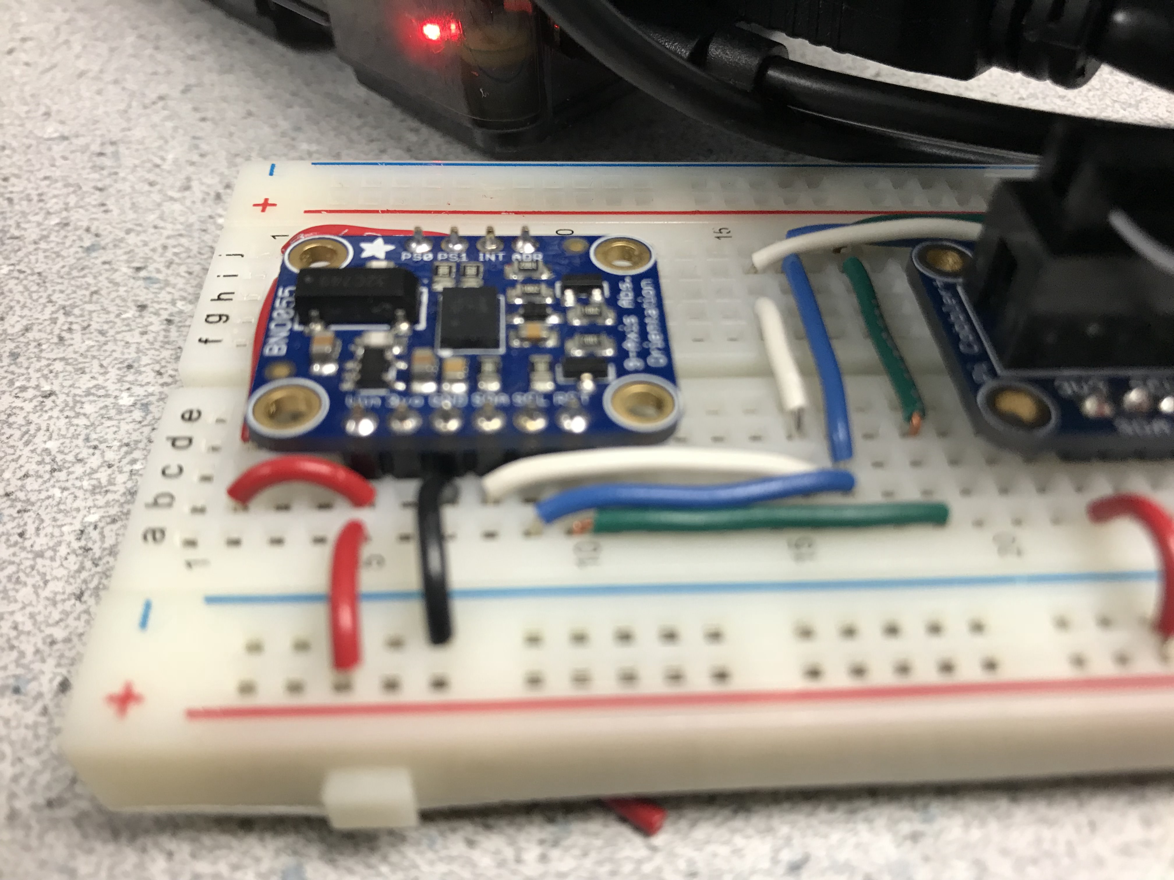
BNO055 Absolute Orientation Sensor
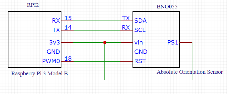
The BNO055 Absolute Orientation Sensor is a combination of sensors including an accelerometer, gyroscope, and magnetometer. The main reason we used the sensor was because we already own one and didn’t need to order it. One only needs the gyroscope to detect the turns of the steering wheel, thus cheaper alternatives are definitely available. The sensor itself abstracts many of the mathematics behind calculation of orientation. We used the sensor to poll for the movement of the steering wheel. Since the I2C communication with the RPi contains some glitches with clock stretching, we decided to use serial communication where we set the SDA pin as TX and SCL pin as RX. We then connect to the serial pins on the RPi. We use the default ‘/dev/serial0’ as our serial port. One problem was that attempted connection with the sensor sometimes fails and returns the error code. We never figured out the reason but we ultimately solved it by using a while and try loop that repeated attempts to connect and prints erros to the terminal for inspection instead of crashing the program. We simply read the registers on the device which contains the euler data which is contained at device address 0x1A. The library sends the serial read command as a series of bytes.
Communication
We have to handle two different means of communication for two peripherals. One for the getting vehicle camera stream to base station and the other for sending sensor data from base station to vehicle.
Considering that we are not going to remotely reboot the vehicle, we set up the vehicle as passive. The vehicle handles request from any IP address, which allows us to reconnect to it after the controller is down or the connection is lost.
Motion Control
Since the control signal is lightweight and non-sensitive to packet loss, we used bare UDP sockets to send and receive control
signal. When power-on, the vehicle will keep listening for instructions from the controller. The vehicle decodes the message
from the UDP and then moves the servos according to the readings from the sensors. The message format is in the form of
“valid:turn:heading:roll:pitch” where each message is separated by a string separator “:”.
The valid message is to check if the UDP message is valid. The turn message is for control enable which enables the user to move
the robot using motion control. The heading, roll, and pitch have a range of 360 to represent the angles the sensor rotates by.
For our implementation of the robot, we only used the roll and pitch values to capture if the steering wheels clockwise
counterclockwise rotation (roll) and forward backward roll (pitch).
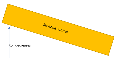
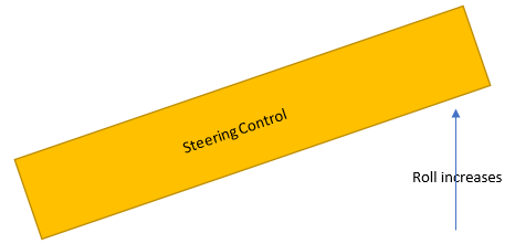
The above figures shows the general control for turning.
If our steering wheel rotates counterclockwise, our roll
value will increase, and vice versa. The pitch will increase on a forward roll and vice versa. We then need to map the roll and
pitch values from the sensor to the servo PWM signals to generate the desired servo rotation speed.
We also set up a function to set the natural position of the steering wheel such that all the turning values will be
relative to the natural position. Where being at the natural position will essentially mean a rotation of zero.
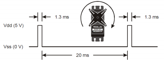
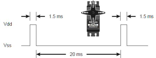
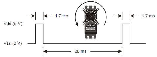
As we done in lab 3, the servos uses a PWM communication with a amount of high period determining the rotation and speed of the servos with a 20ms low value. As shown in the figure above, we have a window of 0.4ms to control the servo rotation and speed. We therefore must map the values of the sensors to 0.4ms. Our range is smaller because we only take into account a turn up to 50 degrees to prevent the user from turning the steering too much. The ultimate result is a vector equation where we set the servo speed based on both the pitch value and roll value multiplied by a slope value which maps the sensor values to the PWM control window. For our robot, Counterclockwise rotation from left servo and clockwise rotation from right servo means forward while clockwise rotation from both servos mean moving left and counterclockwise rotation means left movement.
We don't use the raw readings from the sensor but instead use the sensor readings relative to the natural position of the
steering wheel which should always be set when the system initially starts.
The general equation for calculating the servo movement based on all these information is:
left_time = stop_time + rslope * roll - pslope * pitch
right_time = stop_time + rslope * roll + pslope * pitch
where stop time is 1.5ms and left_time and right_time are bounded into a value between 1.3 and 1.5. Pslope and rslope are
a function of the maximum pitch and roll values respectively where we map the range bounded by the max values to the 0.4ms range
for the servo control.
Through testing, we discovered that having pslope = 2 * rslope is actually better for control of the vehicle to prioritize moving forward as oppose to turning.
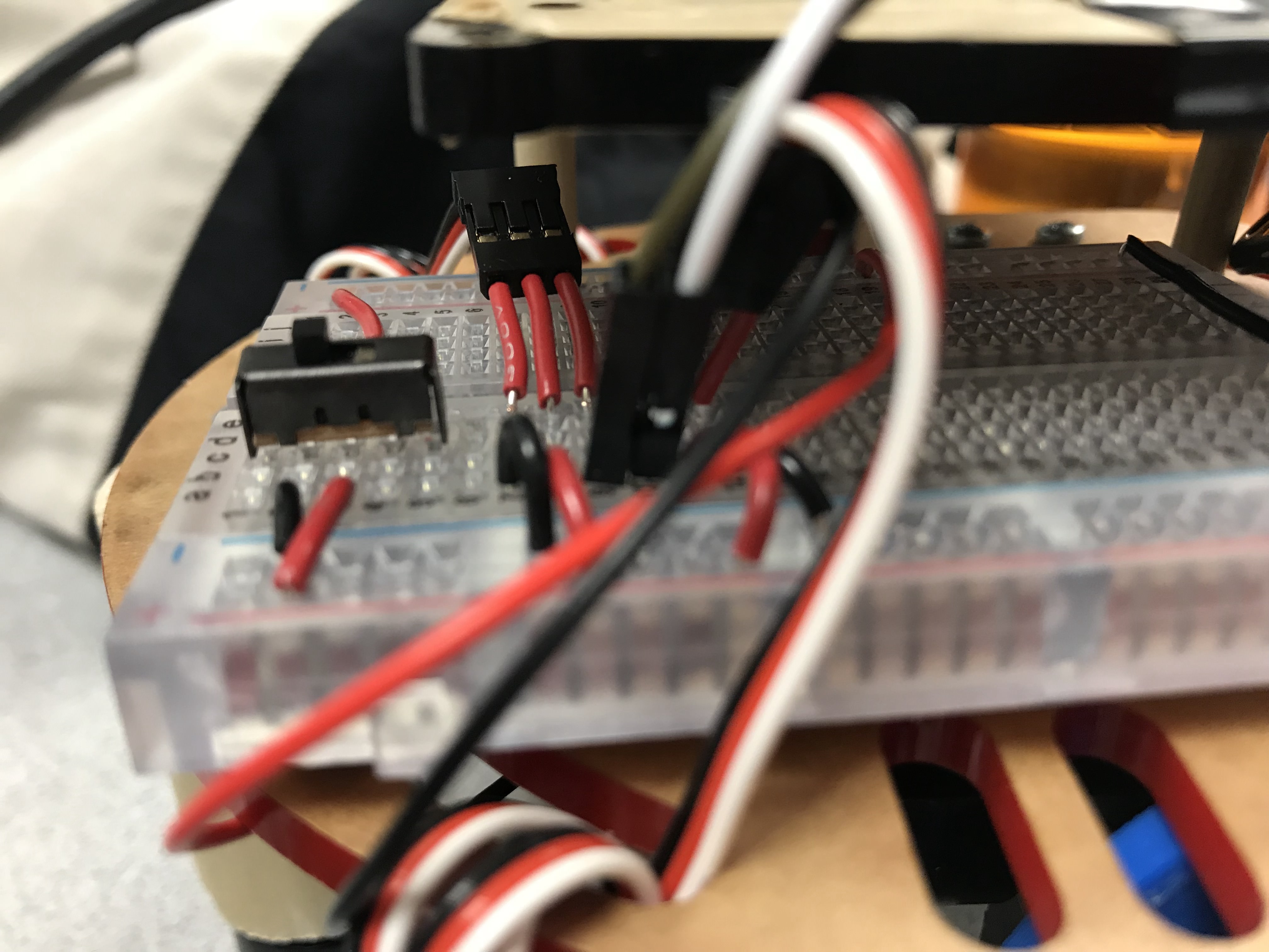
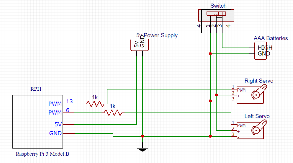
Above is the wiring of the servos to the GPIO pins. We use a 1k resistor between the GPIO and servo control to keep the current down and as an extra safety measure even if the RPi has built in pull up resistors. The switch facilitates testing and saves the energies of the AAA batteries that are mounted under the robot.
Realtime Streaming
Our application requires minimum latency for video streaming in order for safety. We set up a simple HTTP server on the
vehicle which responds to any request with a stream of encoded image. The response starts with a header that specifies the
response as “no-cache” and the data type as “multipart”, followed by a endless stream of JPEG format images bounded by
“\xff\xd8”
and “\xff\xd9”.
The images are extracted from the output byte stream of picamera by redirecting the stream to an custom class
with a “write” method that keeps searching for “\xff\xd8” pattern. When a complete frame has been written,
a condition variable
is triggered and tells the main loop to proceed.
When the controller is getting the requested data stream, images are extracted from the content by searching for boundary patterns and decoded and displayed on the touch screen using pygame. To make the system robust, we handled timeout and broken pipe exception from the controller side by sending periodic requests for reconnection.
Before we turned to HTTP, we also tried using bare TCP protocol. However, the frame rate remained pretty low (around 3 - 5) no matter how we reduced the image size and bit rate. We suspect that the maximum number of requests from a single device that can be handled by the router is around 3-5 per second. So we cannot get over the limit by simply reducing the size of the response. In contrast, since HTTP protocol allows multipart type response, we can send a stream of many images without adding more work load to the router and thus increase the frame rate. For motion control there is a similar limit of 5 instructions per second. However, since it is already satisfying for out application, we did not set up a seperate server to handle the communication of instructions.
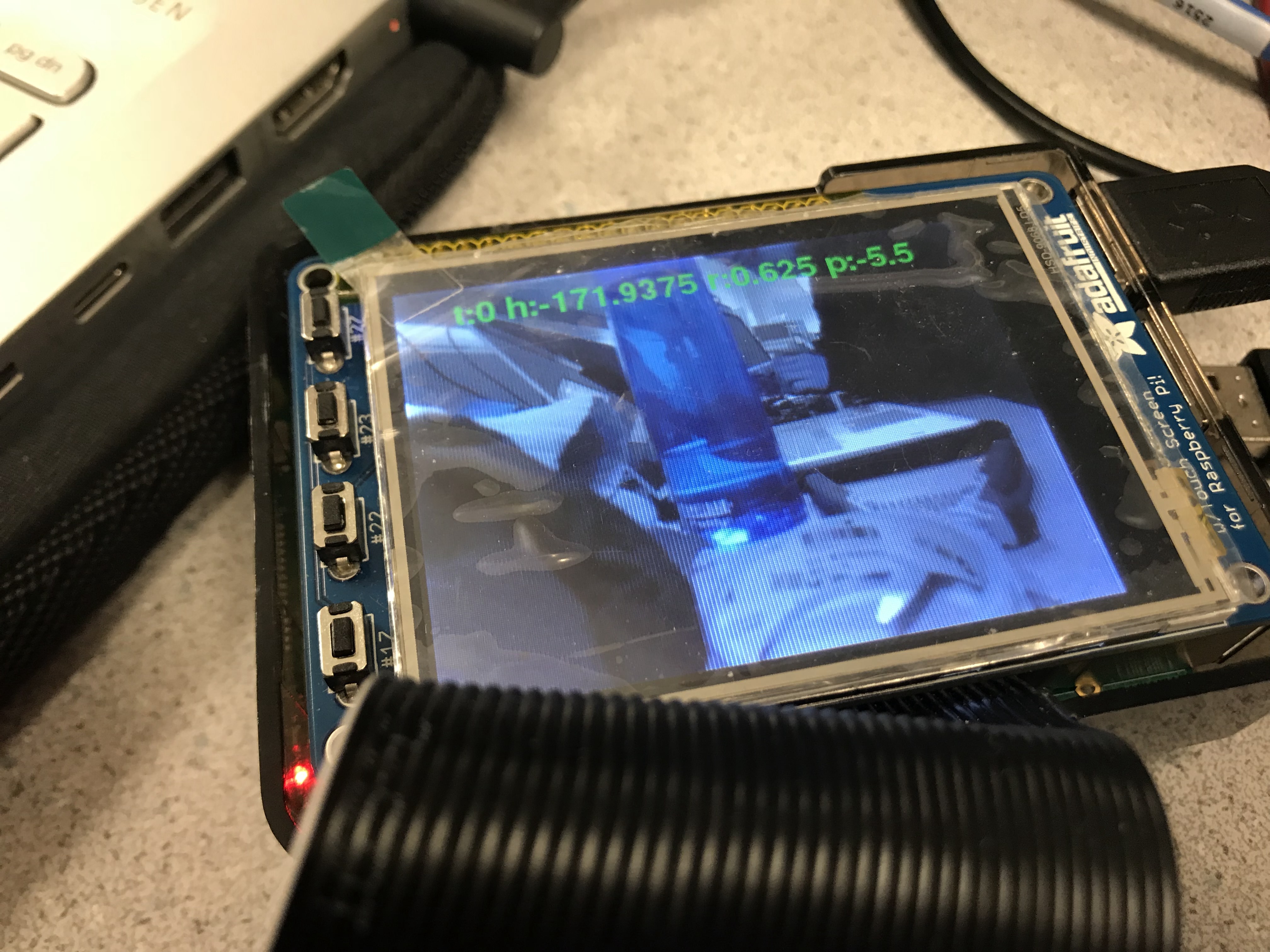
To display the camera stream on the PiTFT, we used the Pygame library that was set up from lab 2. We first use openCV to decode the image data and then save that image data as an numpy array. The Pygame library can display images from numpy arrays as a surface and after that we just blit the surface onto the workspace and display. We also displayed the sensor readings using Pygame. This part was easy given that we worked on it before in lab. We just had to blit the texts on top of the camera feed surface and update the number every iteration of the loop. We also displayed messages to pop up to inform the user that he or she enable or disable vehicle controls. The GUI certainly allows a better user experience and can allow the use to see if the motion sensors are working and help judgement.
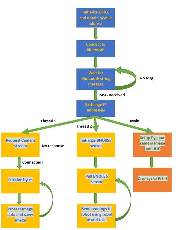
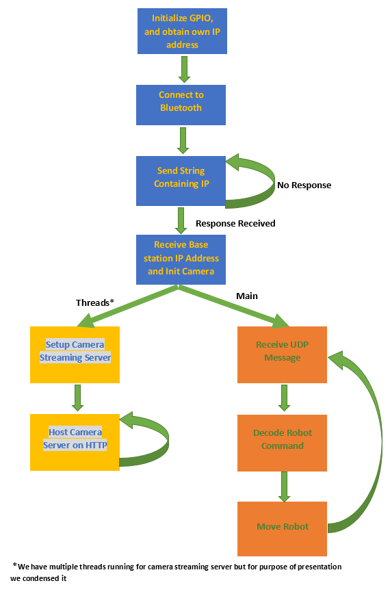
Above contains the control diagram for the entire system.
We can see that both have very similar initial structure but diverges after IP exchange. We execute multiple independent tasks
in our system so we can perform these tasks in parallel using threads which can distribute the workload over multiple cores.
The system itself is not entirely independent and that we have shared variables among threads since behavior of some of the threads depends on
results obtained by others. We did not need to implement any major synchronization however since we initialized the shared variables and
threads such that there is always one writer and reader. The only condition variable we used was for camera streaming.
Testing
We performed an incremental testing strategy for all our our peripherals where we first implement part of the functionality of the robot, test it, and make sure it passes all the tests before we add more functionalities. We also test that each peripheral work separately before integrating them together. Working versions of the code were saved and additional functions were added to new files instead of overriding code.
We also did a lot of test on the motion control to best fit human intuition for driving. For example, we set up an activation threshold for our controller so that the vehicle will stop when the steering wheel is held in a natural way. Also we set the influence of “driving” (roll-changing) operation to be double of the “turning” (pitch-changing) operation to make it easier to make turns while moving forward. For servo tests, we wrote functions in Robot.py that calibrate the servos by having the robot move forward, backwards, left, right, and stop. We have a switch on the vehicle that disconnects the power of the servo from the rest of the system. This allowed us to test the signals to the servos without actually moving the servos.
To test the latency of our camera, we did some simple test such as moving images in front of the camera and see the latency. We also did a more objective test by seeing how many frames per second the robot was able to display. The test of latency can be shown in the video below. As distance between the vehicle and base station increases, the latency also increases. This appears for both remote control and camera feed.
Through testing, we discovered that due to poor wifi, the RPi’s have a tendency to disconnect from the wifi and swap to a
different wifi. This is a problem because our streaming and communications only work when the RPI’s share the same wifi network
and are also connected to wifi. We solved this by ensuring that there is only one eligible wifi at any given location. In the lab,
the RPI recognized RedRover and Cornell Guest. We removed Cornell Guest by going to /etc/wpa_supplicant/wpa_supplicant.conf
and deleting the relevant network block. In the code, we added while and try except statements to have the thread try
repeatedly to reconnect to the server and ignore any error from failure to connect.
Result
The system was overall a success; we were able achieve all of the objectives established above and made a system that was robust to some failures such as wifi. One result that was only satisfactory was the camera latency (on a scale of 1 to 10, it would be a 6). While the latency was much better than when we initially tried with TCP socket, there were still clear lag spikes from wifi slowdowns. This problem is not necessarily implementation; part of the problem could be the RPi 3B’s wifi module. If we had more budget, we could have gotten a module with higher quality and bandwidth. An alternative is to just not use wifi for the base station and instead use ethernet which is much faster than wifi. Other solutions such as better processing of the images sent by the camera were all attempted during the work on the project but to no huge success. Overall, we were able to make progress in camera streaming considering how we were initially getting frame rates of no greater than 5 and not including lag spikes.
The sensor data to robot movement data path was a success but like the camera stream, it was also dependent on the network quality. However, the combination of low byte payload and UDP communication meant that the latency wasn’t too big even with poor network connections. An idea was to have the controls be done with radio but that would conflict with the idea that the robot was suppose to work indoors which is not optimal for radio communications due to obstruction.
Conclusions
We succeeded in building a robust plug-and-use remote driving system which handles latency and loss of connection. We achieved
our goals even if the technologies we planned to use did not work out as expected.
First, we tried out different types of wireless communication. Bluetooth is the first to be discarded and only used for
transmitting metadata because of its limited range. Then we briefly consider lora radio, which can cover over long range but has a
narrow bandwidth and is not capable of video streaming. As for WiFi communication, which we finally used, bare UDP resulted in
serious packet loss and bare TCP connection suffers from high latency and unstable framerate because each packet has to be
re-routed. We originally put in a lot of effort setting up the TCP socket camera streaming server. The reason we put a lot of
effort was that it worked and was extremely promising with latency on a good wifi network being very low and we were able to
get up to 20 FPS on a good wifi. However, later tests saw us struggle to even reach 5 FPS on the sending side. We tried many
different methods such as changing the format of the video to .h264 instead of .mjpeg but to no success. TCP connection was
certainly a solution to camera streaming but the latency was too great given the wifi and hardware we have.
Our final choice is to set up an HTTP server on the vehicle, which perfectly works out with controlled
latency and a stable framerate of 24 frames per second.
Future Work
We would like to add a auto-driving mode for the vehicle so that it will try to return to the place it starts with
backtracking on its movement history after losing reconnection with the controller. Due to development on autonomous robots, we
believe integrating automony is a natural next step for our vehicle. Another idea is to use openCV library for image processing
to detect if walls are too close and stop the robot or have the robot follow a line using openCV. Computer vision and machine
learning has huge research potential for our robot.
On a more immediate note, we also had extra room but not enough time to implement extra vehicle controls. We current only used
three of the four GPIO pins on the PiTFT. The PiTFT also contains touch screen functionality which we can take advantage of by
creating touch screen menus or controls using the touch screen alone. We had motion control for our vehicle but motion control
could have also been a possibility. The vehicle can certainly be repurposed to accomplish a specific task where we can add arms
or microphones. The possibilities are limitless.
Code Appendix
Here contains the main code used in the system. Throughout our project, we also created many modular files for testing various parts of the system and just seeing if something works. The entire Github repository for all the code can be found here.
# client.py
# 12/7/2018
# Xiaoyu Yan (xy97) and Ji Wu (jw2473)
# Final Project - Telepresence Vehicle
#
# Main control file for robot. Sends its IP address to the basestation
# and gets basestation IP address.
# Receives and decodes commands from basestation and sets up a host
# server for the camera stream
# Handles servo movements to control robot movement
#
Click to see client.py
1 2 3 4 5 6 7 8 9 10 11 12 13 14 15 16 17 18 19 20 21 22 23 24 25 26 27 28 29 30 31 32 33 34 35 36 37 38 39 40 41 42 43 44 45 46 47 48 49 50 51 52 53 54 55 56 57 58 59 60 61 62 63 64 65 66 67 68 69 70 71 72 73 74 75 76 77 78 79 80 81 82 83 84 85 86 87 88 89 90 91 92 93 94 95 96 97 98 99 100 101 102 103 104 105 106 107 108 109 110 111 112 113 114 115 116 117 118 119 120 121 122 123 124 125 126 127 128 129 130 131 132 133 134 135 136 137 138 139 140 141 142 143 144 145 146 147 148 149 150 | import RPi.GPIO as GPIO import socket import threading import cv2 import numpy as np import picamera import subprocess import re import time from bluedot.btcomm import BluetoothClient, BluetoothAdapter import io import struct import socketserver from http import server from threading import Condition import Robot #custom library GPIO.setmode(GPIO.BCM) GPIO.setup(6, GPIO.OUT) GPIO.setup(13, GPIO.OUT) p1 = GPIO.PWM(6, 100000/2150) p2 = GPIO.PWM(13, 100000/2150) p1.start(150/2150.0*100) p2.start(150/2150.0*100) ## Get IP address result = subprocess.run('hostname -I', stdout=subprocess.PIPE, shell=True) result = result.stdout.decode('utf-8') client_IP = re.split(' |\n', result)[0] print("client_IP: "+client_IP) PORT1 = 5000 BUFFER_SIZE = 1024 connected = True run = True class StreamingOutput(object): def __init__(self): self.frame = None self.buffer = io.BytesIO() self.condition = Condition() def write(self, buf): if buf.startswith(b'\xff\xd8'): self.buffer.truncate() with self.condition: self.frame = self.buffer.getvalue() self.condition.notify_all() self.buffer.seek(0) return self.buffer.write(buf) class StreamingHandler(server.BaseHTTPRequestHandler): """ Streaming video to HTTP server """ def do_GET(self): if self.path == '/': self.send_response(200) self.send_header('Age', 0) self.send_header('Cache-Control', 'no-cache, private') self.send_header('Pragma', 'no-cache') self.send_header('Content-Type', 'multipart/x-mixed-replace; boundary=FRAME') self.end_headers() try: while True: with output.condition: output.condition.wait() frame = output.frame self.wfile.write(b'--FRAME\r\n') self.send_header('Content-Type', 'image/jpeg') self.send_header('Content-Length', len(frame)) self.end_headers() self.wfile.write(frame) self.wfile.write(b'\r\n') except Exception as e: pass class StreamingServer(socketserver.ThreadingMixIn, server.HTTPServer): allow_reuse_address = True daemon_threads = True def data_received(data): """ Callback function for bluetooth data received """ global host_IP global flag print('host_IP: ' + data) host_IP = data flag = False def sendIP(): """ Repeatedly sends the string containing IP address to target. Requires the MAC address of the target to be hardcoded. Receives back IP address from target and saves it for UDP connection Blocks until we connect with base station """ global flag flag = True c = BluetoothClient('B8:27:EB:2A:46:91', data_received, power_up_device=True) while flag: c.send(client_IP) time.sleep(1) c.disconnect() sendIP() ### Connection good!! Start everything else s1 = socket.socket(socket.AF_INET, socket.SOCK_DGRAM) s1.bind((client_IP, PORT1)) s1.setblocking(0) camera = picamera.PiCamera(resolution=(320, 240), framerate=24) output = StreamingOutput() camera.start_recording(output, format='mjpeg') address = ('', 8000) server = StreamingServer(address, StreamingHandler) def func(server): """ Threading function for hosting camera stream """ server.serve_forever() thread = threading.Thread(target=func, args=(server,)) thread.setDaemon = True thread.start() robot = Robot.Robot() t = 0 while run: try: data = s1.recv(BUFFER_SIZE) data = data.decode('utf-8') robot.command(data) print(data) t = time.time() + 1 except BlockingIOError: data = "0:0:0:0:0" #sends invalid data to stop robot if time.time()>t: robot.command(data) |
# mainserver_v2.py
# 12/7/2018
# Xiaoyu Yan (xy97) and Ji Wu (jw2473)
# Final Project - Telepresence Vehicle
#
# Main control for the basestation. Handles communication with robot
# through bluetooth, then receives camera data from the robot. Also
# displays the camera images to the PiTFT and any GUI.
#
Click to see mainserver_v2.py
1 2 3 4 5 6 7 8 9 10 11 12 13 14 15 16 17 18 19 20 21 22 23 24 25 26 27 28 29 30 31 32 33 34 35 36 37 38 39 40 41 42 43 44 45 46 47 48 49 50 51 52 53 54 55 56 57 58 59 60 61 62 63 64 65 66 67 68 69 70 71 72 73 74 75 76 77 78 79 80 81 82 83 84 85 86 87 88 89 90 91 92 93 94 95 96 97 98 99 100 101 102 103 104 105 106 107 108 109 110 111 112 113 114 115 116 117 118 119 120 121 122 123 124 125 126 127 128 129 130 131 132 133 134 135 136 137 138 139 140 141 142 143 144 145 146 147 148 149 150 151 152 153 154 155 156 157 158 159 160 161 162 163 164 165 166 167 168 169 170 171 172 173 174 175 176 177 178 179 180 181 182 183 184 185 186 187 188 189 190 191 192 193 194 195 196 197 198 199 200 201 202 203 204 205 206 207 208 209 210 211 212 213 214 215 216 217 218 219 220 221 222 223 224 225 226 227 228 229 230 231 232 233 234 235 236 237 238 239 240 241 242 243 244 245 246 | import socket import sys import subprocess import re import time import threading import cv2 import numpy as np import requests from PIL import Image from bluedot.btcomm import BluetoothServer, BluetoothAdapter import RPi.GPIO as GPIO import pygame import os import bno #custom module os.putenv('SDL_VIDEODRIVER', 'fbcon') # Display on piTFT os.putenv('SDL_FBDEV', '/dev/fb1') os.putenv('SDL_MOUSEDRV', 'TSLIB') #setup mouse in pygame os.putenv('SDL_MOUSEDEV', '/dev/input/touchscreen') #touchscreen as mouse result = subprocess.run('hostname -I', stdout=subprocess.PIPE, shell=True) result = result.stdout.decode('utf-8') host_IP = re.split(' |\n', result)[0] print("host_IP: "+host_IP) result = subprocess.run('hcitool dev|grep hci0', stdout=subprocess.PIPE, shell=True) result = result.stdout.decode('utf-8') host_mac = re.split(' |\n|\t', result)[2] print("host_mac: "+host_mac) client_IP = '10.148.4.162' #default Client IP code_running = True turn = 0 #######GPIO CALLBACK FUNCTIONS (Interrupt Handlers)############ def GPIO22_callback(channel): """ interrupt handler for GPIO17; button on piTFT Sets the control enabled bit for whether we are turning on motion controls on the robot """ print ("in interrupt 22") global turn turn = 1 if turn==0 else 0 def GPIO23_callback(channel): """ Unused """ print ("in interrupt 23") def GPIO27_callback(channel): """ Exits the program. Breakout button """ print ("in interrupt 27") global code_running code_running = False GPIO.cleanup() sys.exit(0) GPIO.setmode(GPIO.BCM) GPIO.setup(22, GPIO.IN, pull_up_down=GPIO.PUD_UP) GPIO.setup(23, GPIO.IN, pull_up_down=GPIO.PUD_UP) GPIO.setup(27, GPIO.IN, pull_up_down=GPIO.PUD_UP) GPIO.add_event_detect(22,GPIO.FALLING,callback=GPIO22_callback, bouncetime=300) GPIO.add_event_detect(23,GPIO.FALLING,callback=GPIO23_callback, bouncetime=300) GPIO.add_event_detect(27,GPIO.FALLING,callback=GPIO27_callback, bouncetime=300) size = 320,240 screen = pygame.display.set_mode(size) pygame.init() pygame.mouse.set_visible(False) my_font = pygame.font.Font(None,30) COMMAND_PORT=5000 CAM_PORT = 8000 BUFFER_SIZE = 1024 get_ip() time.sleep(2) def data_received(data): """ Callback fuction for receiving bluetooth messages """ global client_IP global flag print("Got IP from Client! IP: "+ str(data)) client_IP = data flag = False def get_ip(): """ Receives sender IP through bluetooth Relays its IP back to the sender using send's IP that was received Also generates pygame GUI to inform user that we are looking for bluetooth. Blocks until one robot connects """ global flag blue = BluetoothServer(data_received, power_up_device=True) flag = True i = 0 while flag: screen.fill((0,0,0)) mytext = "Connecting to Bluetooth" if(i==0): mytext = mytext+'.' elif (i==1): mytext = mytext+'..' elif (i==2): mytext = mytext+'...' else: i=-1 i+=1 text_surface = my_font.render(mytext,True,(255,255,255)) text_surface = pygame.transform.rotate(text_surface,180) rect = text_surface.get_rect(center=(160, 120)) screen.blit(text_surface,rect) time.sleep(1) pygame.display.flip() blue.send(host_IP) blue.stop() def camera_receive(client_IP): """ Requests video feed from a server hosted by the Robot. Saves the images in an encoded array """ while code_running: try: r= requests.get('http://' + client_IP + ':8000', stream=True, timeout=5) if(r.status_code == 200): bytes1 = bytes() global image for chunk in r.iter_content(chunk_size=1024): bytes1 += chunk a = bytes1.find(b'\xff\xd8') b = bytes1.find(b'\xff\xd9') if a != -1 and b != -1: jpg = bytes1[a:b+2] bytes1 = bytes1[b+2:] image = cv2.imdecode(np.fromstring(jpg, dtype=np.uint8), cv2.IMREAD_COLOR) image = np.flip(image, axis=1) except Exception as e: print("error :{}".format(e)) time.sleep(1) h = 0 #global variables for BNO055 data r = 0 p = 0 def send_command(): """ Sends the BNO055 data to the robot. This function is ran in a thread that regularly checks the sensor for data to send. The message is send using UDP socket. The message format is: valid:control:heading:roll:pitch valid : if message sent is valid control: control enable heading: not used roll : control robot direction pitch : control robot speed and forward/backward movement """ global h,r,p while code_running: command_server = socket.socket(socket.AF_INET, socket.SOCK_DGRAM) bno.bno_init() try: while code_running: h,r,p = bno.bno_poll() message = str(1)+":"+str(turn)+":"+str(h)+":"+str(r)+":"+str(p) command_server.sendto(message.encode(), (client_IP, COMMAND_PORT)) time.sleep(0.3) #defines the period of when to check and send data except Exception as e: print("error :{}".format(e)) command_server.close() th = threading.Thread(target=camera_receive, args=(client_IP,)) th.setDaemon = True th.start() command_thread = threading.Thread(target=send_command) command_thread.setDaemon = True command_thread.start() image = np.zeros((320, 240), dtype=np.uint8) t = 0 turn_p = turn while code_running: try: surf = pygame.Surface((image.shape[0], image.shape[1])) pygame.surfarray.blit_array(surf, image.astype(np.int)) rect1 = surf.get_rect() surf = pygame.transform.rotate(surf, 90) rect1.x = 0 rect1.y = 0 screen.blit(surf, rect1) my_font_hud = pygame.font.Font(None,8) my_text_hud = 't:'+str(turn)+' h:'+str(h)+' r:'+str(r)+' p:'+str(p) text_surface_hud = my_font.render(my_text_hud,True,(50,255,50)) text_surface_hud = pygame.transform.rotate(text_surface_hud,180) rect = text_surface_hud.get_rect(center=(160, 220)) screen.blit(text_surface_hud,rect) if(turn_p != turn): t = time.time() + 2 turn_p = turn if time.time() < t: if turn == True: my_text = 'Control Enabled!' else: my_text = 'Control Disabled!' text_surface = my_font.render(my_text,True,(255,0,255)) text_surface = pygame.transform.rotate(text_surface,180) rect = text_surface.get_rect(center=(160, 120)) screen.blit(text_surface,rect) pygame.display.flip() except KeyboardInterrupt: code_running = False GPIO.cleanup() sys.exit(0) |
The below files are modules we made testing the sensor and robot. They were made into functions and classes and imported to main files for usage. This shows the modularity of our code.
# Robot.py
# 12/7/2018
# Xiaoyu Yan (xy97) and Ji Wu (jw2473)
# Final Project - Telepresence Vehicle
#
# Robot class for controling the robot by setting the timings for
# the GPIO pins. We also decode control messages from the basestation.
#
Click to see Robot.py
1 2 3 4 5 6 7 8 9 10 11 12 13 14 15 16 17 18 19 20 21 22 23 24 25 26 27 28 29 30 31 32 33 34 35 36 37 38 39 40 41 42 43 44 45 46 47 48 49 50 51 52 53 54 55 56 57 58 59 60 61 62 63 64 65 66 67 68 69 70 71 72 73 74 75 76 77 78 79 80 81 82 83 84 85 86 87 88 89 90 91 92 93 94 95 96 97 98 99 100 101 102 103 104 105 106 107 108 109 110 111 112 113 114 115 116 117 118 119 120 121 122 123 124 125 126 127 128 129 130 131 132 133 134 135 136 137 138 139 140 141 142 143 144 145 146 147 148 149 150 151 152 153 154 155 156 157 158 159 160 161 162 163 164 165 166 | import RPi.GPIO as GPIO import time class Robot: """ Initializes the two servos using RPi.GPIO library to control GPIO. Handles the timing of the servos and sets the speed and rotation directions of the robot """ LEFT_SERVO_PIN = 6 RIGHT_SERVO_PIN = 13 STOP_T = 0.0015 CLKW_T = 0.0013 CCLKW_T = 0.0017 DOWN_T = 0.02 STOP_DC = STOP_T/(STOP_T+DOWN_T)*100 #cycle in percentage STOP_FREQ = 1/(STOP_T+DOWN_T) def __init__(self): GPIO.setmode(GPIO.BCM) GPIO.setup(self.LEFT_SERVO_PIN, GPIO.OUT) GPIO.setup(self.RIGHT_SERVO_PIN, GPIO.OUT) self.right_speed = self.STOP_T self.left_speed = self.STOP_T self.left_servo = GPIO.PWM(self.LEFT_SERVO_PIN, self.STOP_FREQ) self.right_servo = GPIO.PWM(self.RIGHT_SERVO_PIN, self.STOP_FREQ) self.left_servo.start(self.STOP_DC) self.right_servo.start(self.STOP_DC) def stop(self): self.left_servo.ChangeDutyCycle(self.STOP_DC) self.right_servo.ChangeDutyCycle(self.STOP_DC) self.left_servo.ChangeFrequency(self.STOP_FREQ) self.right_servo.ChangeFrequency(self.STOP_FREQ) def forward(self): print("Moving forward") self.left_servo.ChangeDutyCycle(self.CCLKW_T/(self.CCLKW_T+self.DOWN_T)*100) self.left_servo.ChangeFrequency(1/(self.CCLKW_T+self.DOWN_T)) self.right_servo.ChangeDutyCycle(self.CLKW_T/(self.CLKW_T+self.DOWN_T)*100) self.right_servo.ChangeFrequency(1/(self.CLKW_T+self.DOWN_T)) def left(self): print("Moving left") self.left_servo.ChangeDutyCycle(self.CLKW_T/(self.CLKW_T+self.DOWN_T)*100) self.left_servo.ChangeFrequency(1/(self.CLKW_T+self.DOWN_T)) self.right_servo.ChangeDutyCycle(self.CLKW_T/(self.CLKW_T+self.DOWN_T)*100) self.right_servo.ChangeFrequency(1/(self.CLKW_T+self.DOWN_T)) def right(self): print("Moving right") self.left_servo.ChangeDutyCycle(self.CCLKW_T/(self.CCLKW_T+self.DOWN_T)*100) self.left_servo.ChangeFrequency(1/(self.CCLKW_T+self.DOWN_T)) self.right_servo.ChangeDutyCycle(self.CCLKW_T/(self.CCLKW_T+self.DOWN_T)*100) self.right_servo.ChangeFrequency(1/(self.CCLKW_T+self.DOWN_T)) def set_speed(self, interval1, interval2): print(str(interval1) + ' ' + str(interval2)) if interval1 !=-1: self.left_servo.ChangeDutyCycle(interval1/(self.DOWN_T+interval1)*100) self.left_servo.ChangeFrequency(1/(self.DOWN_T+interval1)) if interval1 != -1: self.right_servo.ChangeDutyCycle(interval2/(self.DOWN_T+interval2)*100) self.right_servo.ChangeFrequency(1/(self.DOWN_T+interval2)) def command(self, input_str): ''' Decodes message from the base station Values_List = [Valid,turn,heading,roll,pitch] Parameter input_str: string of commands sent through UDP Moves robot if turn is 1 Stops robot if turn or valid is 0 Decodes the robot speed and direction based on heading and pitch ''' data = input_str.split(':') valid = int(data[0]) if valid: turn = int(data[1]) if turn: h = float(data[2]) r = float(data[3]) p = float(data[4]) if r>180: r-=360 elif r<-180: r+=360 if p>180: p-=360 elif p<-180: p+=360 threshold = 5 if r<threshold and r>-threshold: r = 0 if p<threshold and p>-threshold: p = 0 roll_max = 50 roll_min = -50 pitch_max = 50 pitch_min = -50 if r<roll_min: roll = roll_min elif r>roll_max: roll = roll_max else: roll = r if p<pitch_min: pitch = pitch_min elif p>pitch_max: pitch = pitch_max else: pitch = p rslope = 0.0001/roll_max pslope = 2*rslope left = self.left_speed + rslope*roll - pslope * pitch right = self.right_speed + rslope*roll + pslope * pitch if left>self.CCLKW_T: left = self.CCLKW_T if right<self.CLKW_T: right = self.CLKW_T self.set_speed(left,right) print ("left: "+str(left)+" right:"+str(right)) else: self.stop() else: self.stop() def calibrate(self): """ Calibrates the servo by setting the robot to move in all four directions """ self.left_servo.start(self.STOP_DC) self.right_servo.start(self.STOP_DC) self.stop() time.sleep(5) self.forward() time.sleep(5) self.right() time.sleep(5) self.left() time.sleep(5) def shutdown(self): GPIO.cleanup() if __name__=='__main__': robot = Robot() robot.calibrate() robot.shutdown() |
# bno.py
# 12/7/2018
# Xiaoyu Yan (xy97) and Ji Wu (jw2473)
# Final Project - Telepresence Vehicle
# Inspired from Adafruit_Python_BNO055 library
#
# Handler for reading BNO055 sensor data. We poll the sensor
# for a combination of values such as sensor heading, roll,
# and pitch. We also have a set zero function that provides
# us a way to set the natural position values and send values
# relative to those natural position values.
#
Click to see bno.py
1 2 3 4 5 6 7 8 9 10 11 12 13 14 15 16 17 18 19 20 21 22 23 24 25 26 27 28 29 30 31 32 33 34 35 36 37 38 39 40 41 42 43 44 45 46 47 48 49 50 51 52 53 54 55 56 57 58 59 60 61 62 63 64 65 66 67 68 69 70 71 72 73 74 75 76 77 78 79 80 81 82 83 84 85 86 87 88 89 90 91 92 93 94 95 96 97 98 99 100 101 102 | import logging import sys import time from Adafruit_BNO055 import BNO055 import RPi.GPIO as GPIO GPIO.setmode(GPIO.BCM) GPIO.setup(17, GPIO.IN, pull_up_down=GPIO.PUD_UP) is_calibrating = False zero_heading = 0 zero_roll = 0 zero_pitch = 0 bno = 0 def GPIO17_callback(channel): """ interrupt handler for GPIO17; button on piTFT Changes to whether we are calibrating or not """ print ("in interrupt 17") global is_calibrating is_calibrating = not is_calibrating GPIO.add_event_detect(17, GPIO.FALLING, callback=GPIO17_callback, bouncetime=300) def calibrate(bno): """ Set up the natural position the sensor values by setting the global zero_heading, zero_roll and zero_pitch values. These are the natural position values. """ print("CALIBRATING") global zero_heading, zero_roll, zero_pitch while (is_calibrating): print("CALIBRATING") #bno.set_calibration(bno.get_calibration()) zero_heading, zero_roll, zero_pitch = bno.read_euler() sys, gyro, accel, mag = bno.get_calibration_status() # Print everything out. print('Heading={0:0.2F} Roll={1:0.2F} Pitch={2:0.2F}\tSys_cal={3} \ Gyro_cal={4} Accel_cal={5} Mag_cal={6}'.format( zero_heading, zero_roll, zero_pitch, sys, gyro, accel, mag)) time.sleep(1) def bno_init(): """ Initializes the BNO055 sensor. Handles when BNO connection fails. """ global bno bno = BNO055.BNO055(serial_port='/dev/serial0', rst=18) #if len(sys.argv) == 2 and sys.argv[1].lower() == '-v': # logging.basicConfig(level=logging.DEBUG) while True: try: if not bno.begin(): raise RuntimeError('Failed to initialize BNO055! Is the sensor connected?') status, self_test, error = bno.get_system_status() break except Exception as e: print("error :{}".format(e)) time.sleep(0.5) print('System status: {0}'.format(status)) print('Self test result (0x0F is normal): 0x{0:02X}'.format(self_test)) # Print out an error if system status is in error mode. if status == 0x01: print('System error: {0}'.format(error)) print('See datasheet section 4.3.59 for the meaning.') # Print BNO055 software revision and other diagnostic data. sw, bl, accel, mag, gyro = bno.get_revision() print('Software version: {0}'.format(sw)) print('Bootloader version: {0}'.format(bl)) print('Accelerometer ID: 0x{0:02X}'.format(accel)) print('Magnetometer ID: 0x{0:02X}'.format(mag)) print('Gyroscope ID: 0x{0:02X}\n'.format(gyro)) def bno_poll(): """ Polls from BNO and also checks calibration values """ if is_calibrating: calibrate(bno) # Read the Euler angles for heading, roll, pitch (all in degrees). heading, roll, pitch = bno.read_euler() # Read the calibration status, 0=uncalibrated and 3=fully calibrated. sys, gyro, accel, mag = bno.get_calibration_status() # Print everything out. #print('Heading={0:0.2F} Roll={1:0.2F} Pitch={2:0.2F}\tSys_cal={3} \ # Gyro_cal={4} Accel_cal={5} Mag_cal={6}'.format( # heading, roll, pitch, sys, gyro, accel, mag)) D_H = heading-zero_heading D_R = roll-zero_roll D_P = pitch-zero_pitch #print ("D_H = {0:0.2F} D_R = {1:0.2F} D_P={2:0.2F}".format( #D_H, D_R, D_P)) return (D_H, D_R, D_P) |
Work Distribution
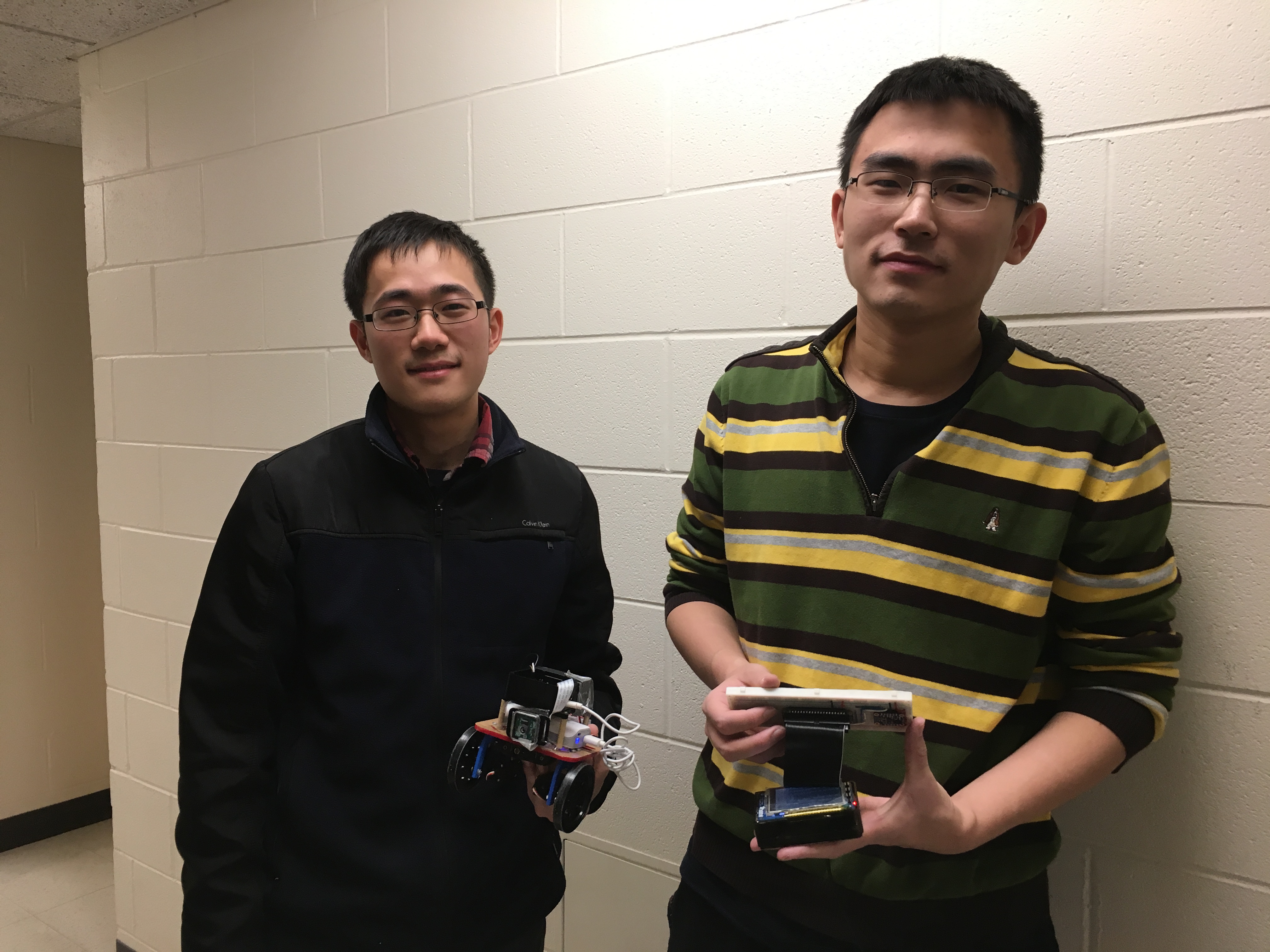
Project group picture
Xiaoyu Yan (xy97)
xy97@cornell.edu
Worked on sensor, vehicle controls and bluetooth communications.
Ji Wu
jw2473cornell.edu
Worked on camera capture to streaming and developed vehicle control equation
Parts List
References
Here are some references for the final project. We did a lot of research on the bluetooth and Pi camera and plausiblity of our vision.
Acknowledgements
Special thanks to Prof. Skovira and the TA staffs for helping us during the labs and final project sections For this project, lab 1, 2, and 3 allowed us to easily set up the PiTFT and Pygame GUI on the PiTFT. We obtained the background to control the servos from lab 3. Overall, this class was entertaining and we learned a lot about embedded operating systems through the Raspberry Pi and using it as a more powerful alternative to microcontroller based embedded systems.
Class Website─▄▒▒▒▒▒▒─▄▒▒▄▒▒─▄▒▒▄▒▒
─▀▀█▒▒▀──█▒▒▒▒▒─▀█▒▒▒
───█▒▒───█▒▒█▒▒─▄▒▒█▒▒
───▀▀────▀▀─▀▀──▀▀─▀▀─