MindBot
Using a Brain Controlled Interface for Simple Robotic Motion
By Mira Bhut and Seetha Kolli.
Demonstration Video
Introduction
An EEG, or electroencephalogram is a test that measures the electrical signals output by the brain through the use of electrodes placed on the head of the subject. EEGs were historically reserved for use in the medical field as a diagnostic test. However, in recent years, many engineers and have discovered that there exist many exciting applications for EEG technology in research, control engineering, and consumer products among many others. Thanks to the growth in this field, technology has not only improved, but so have resources for independent developers and price points of commercial headsets. One such headset, the MindFlex, is available at a very low cost as part of a fun family game. However we think that this headset is capable of much more than just a game controller. With “MindBot” we hope to show some of the possibilities that exist for use of EEG interfaces in modern technology and future advancements.
Project Objective:
- Hack a mind flex headset for general EEG use.
- Show proof of concept for applications of low cost EEG technology.
- Control a mechanical system using two distinct signals.
Design
Our project was broken down into 4 main phases: Hacking the Mindflex headset, Obtaining Data via Bluetooth, and Data Processing (in the form of the robot), and the GUI. In figure 1 you can see the Mindflex headset with the attached bluetooth module. In figure 2 you can see the robot with the attached raspberry pi and TFT touchscreen.
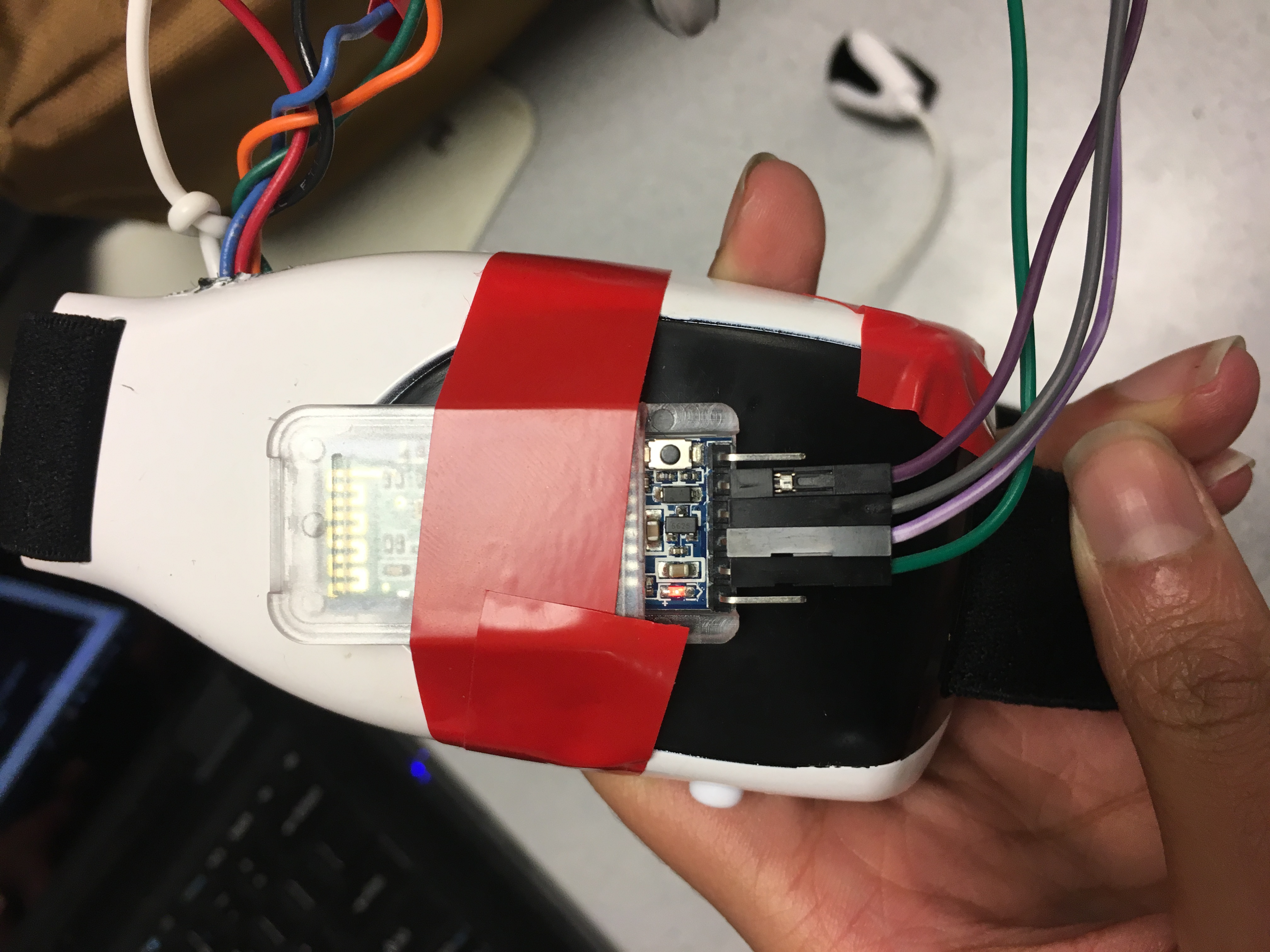
Fig 1: Headset with attached HC05
Hacking the Headset
Out of the box, the chip inside the mind flex headset is only set up to communicate with the board inside the base of the game. In order to communicate with the chip, we had to attach our own bluetooth module directly to the board. We got this idea from a tutorial on instructables.com. This involved soldering jumper wires to the TX, RX, V+ and GND of the chip. We then connected the V+ and GND accordingly; the TX of the chip went to the RX of our bluetooth module, and the RX of the chip went to the TX of our bluetooth module. During this process we considered multiple different bluetooth modules, including the HC06 and the Adafruit Bluefruit LE UART Friend. Between the two HC models, the HC05 is much more user friendly. The Friend is actually the most user friendly, as it is programmable via standard FTDI cables and comes with many accessible libraries. However, in order to dynamically switch between receiving and transmitting data to over bluetooth, it requires an external circuit. The Neurosky chip within the headset has multiple modes of data transmission, out of the box, the chip in the mindflex is automatically configured for mode 1, which is data that has already been processed via fast fourier transform and is transmitted at a baud rate of 9600. In order to get raw data, the chip needs to be switched to mode 2 and will transmit at a baud rate of 57600. One way to do this is to remove a surface mount resistor (see the Instructable for more information). Another way to do this is to transmit a hex byte from the pi to the Neurosky chip. We were wary of the first method as we did not want to irreperably damage the headset, but the second method does not survive power cycling. This means that we would have to transmit the byte every time the headset was powered up. For this reason, we felt it would be more prudent to go with a chip capable of dynamically switching modes.
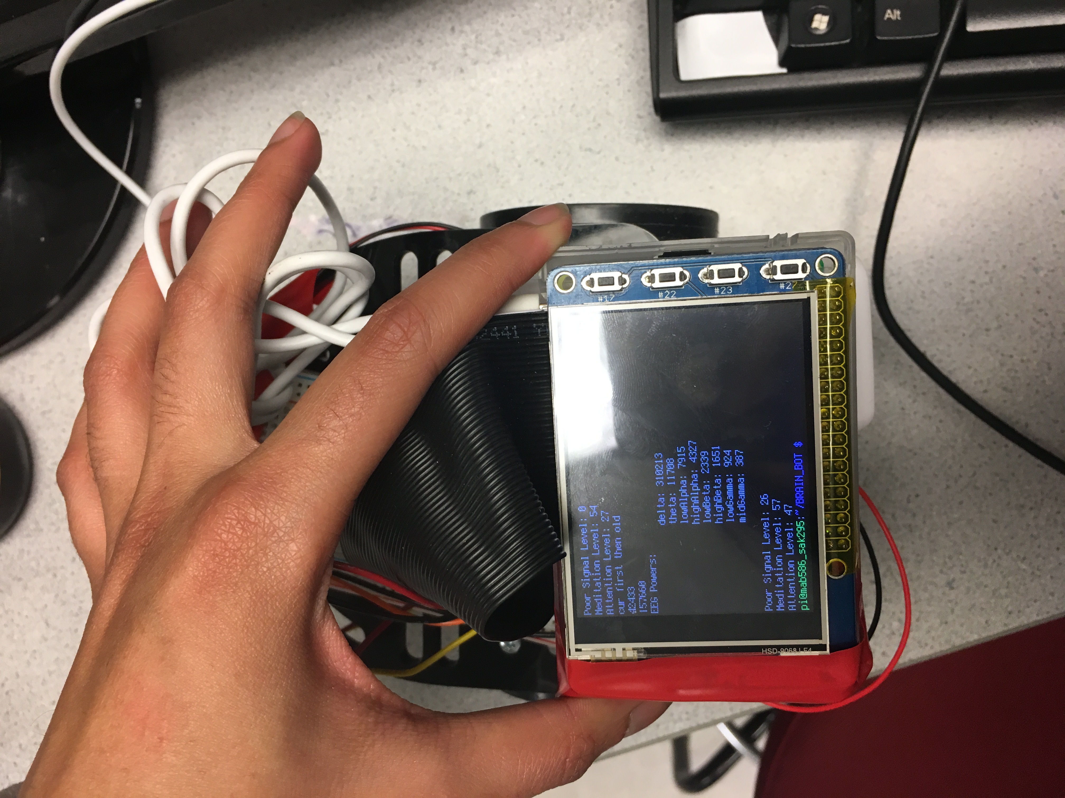
Fig 2: Raspberry pi attached to robot
Bluetooth
The trickiest part of implementation of the MindBot was in creating a reliable bluetooth connection that we could read the data from. After a significant amount of trial and error, the best route ended up being to create a socket connection through the rfcomm port using the RPi as a host and the HC05 as a client. There is no standard UUID protocol for the Neurosky chip, so we used existing mindwave libraries to read directly from the buffer, and altered the libraries as needed to fit our application.
Data Processing
In order to move the bot, we read the wearer's attention level and correlate that to a speed. We wanted to switch between moving straight and turning when the user blinks. When there is a peak the user has blinked. The first part of this involved reading in the data from the neurosky chip. Each data byte is proceeded by a hex row code indicating what type of data is contained within that byte. There are two row codes available for attention level and blink strength. Other row codes include raw data, meditation level, an EEG power spectrum, and a value indicating a power electrical connection between the electrode in the headseat and the wearer. The libraries we were using to process the data created an object with a class based on the row code for each data point. We would read in the byte, check the class, and if it was an attention level data point, we would update the speed and the gui then move the robot. If the data point was a blink, we would update the direction of one of the servos, then move the bot.
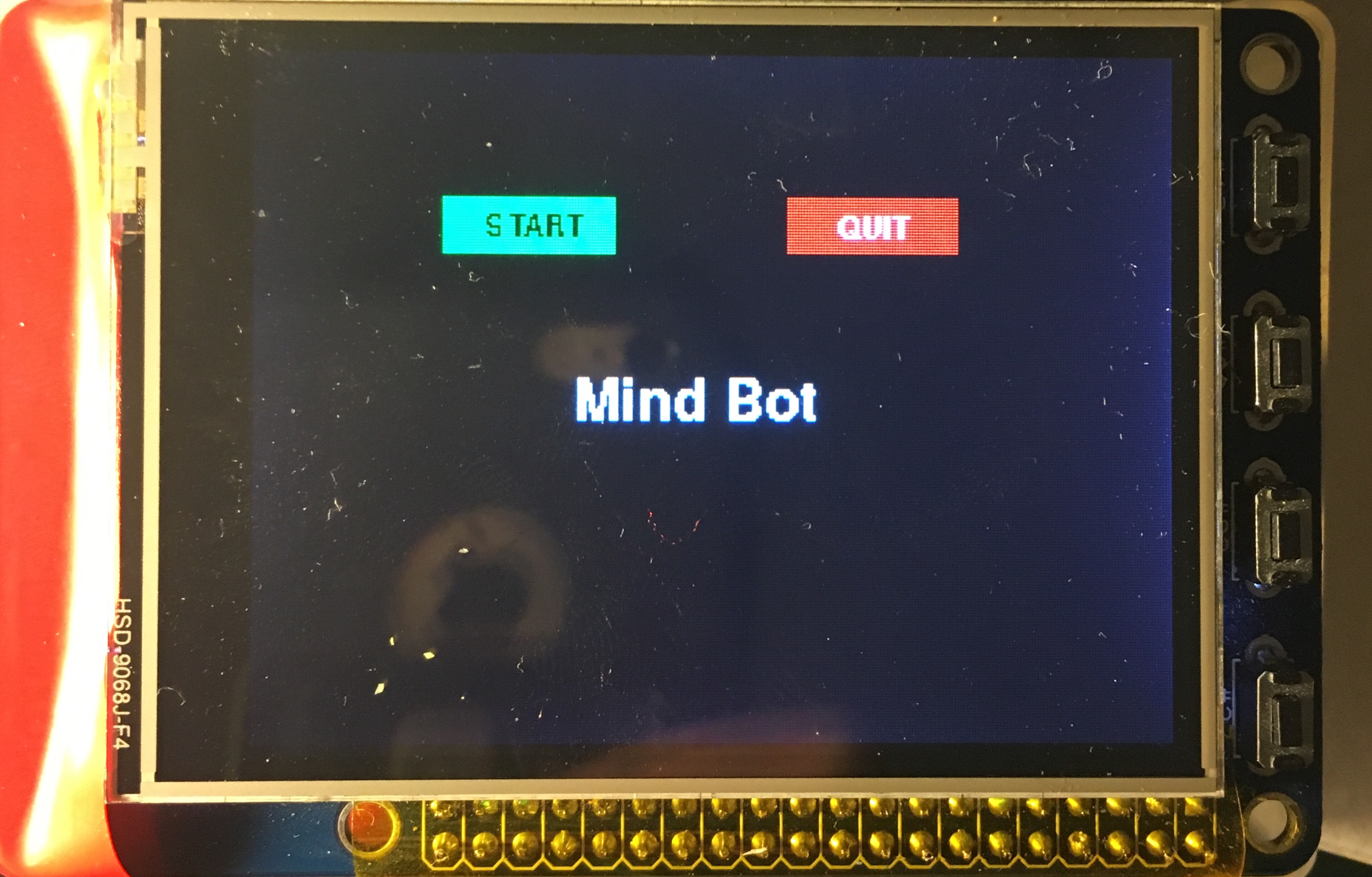
Fig 3: Start Screen
According to the servo datasheets, a neutral position occurs when the servo is sent a pulse width of 1.3 ms with a 20 ms gap between each pulse. This corresponds to a 7.5 percent duty cycle. Maximum clockwise rotation is achieved with a pulse width of 1.5 ms, which corresponds to an 8.5 percent duty cycle, while a maximum counterclockwise rotation corresponds to a 6.5 percent duty cycle. The attention level received has a range of 0 to 100. we multiply this percentage by the difference between the maximum speed duty cycle and the neutral duty cycle (1%) and add that value to the neutral signal. When we do this, we make sure that the servo continues rotating in the same direction, but this allows the speed to vary linearly with concentration level.
As we worked, we discovered that the mindflex headset is not configured to perform blink detection, meaning that although the chip is capable of doing so, the chip was configured so that it never output a byte with a row code corresponding to a blink. However the EEG power spectrum byte contains values representing each of 8 different types of waves, delta, theta, low alpha, high alpha, low beta, high beta, low gamma, and mid gamma. Upon researching, we found that a blink causes a spike in the amplitude of brain waves between the 8 types of brain waves. In order to detect a blink, we calculate the average value of the wearer's mind waves over the time they've been wearing the headseat and compare that to the current average of their brain waves. If the difference is above a certain threshhold, we consider that event a blink. Therefore we adjusted our algorithm to enter the blink detection function when we received a data point with a row code indicating an EEG power spectrum byte. The implementation of this code may be seen in the appendix.
One of the tough parts about the blink detection is that the data is received from the headset at a rate of roughly 1 Hz. This means if the user blinks in between data points being received, the data indicating a spike in brain activity will not be transmitted to the raspberry pi. This is a hardware limitation of the mindflex headset and could possibly be combatted using a more expensive model that is capable of continuous data streaming, however that would lie outside the scope of this project as our goal is to show the possiblities of a low cost module.
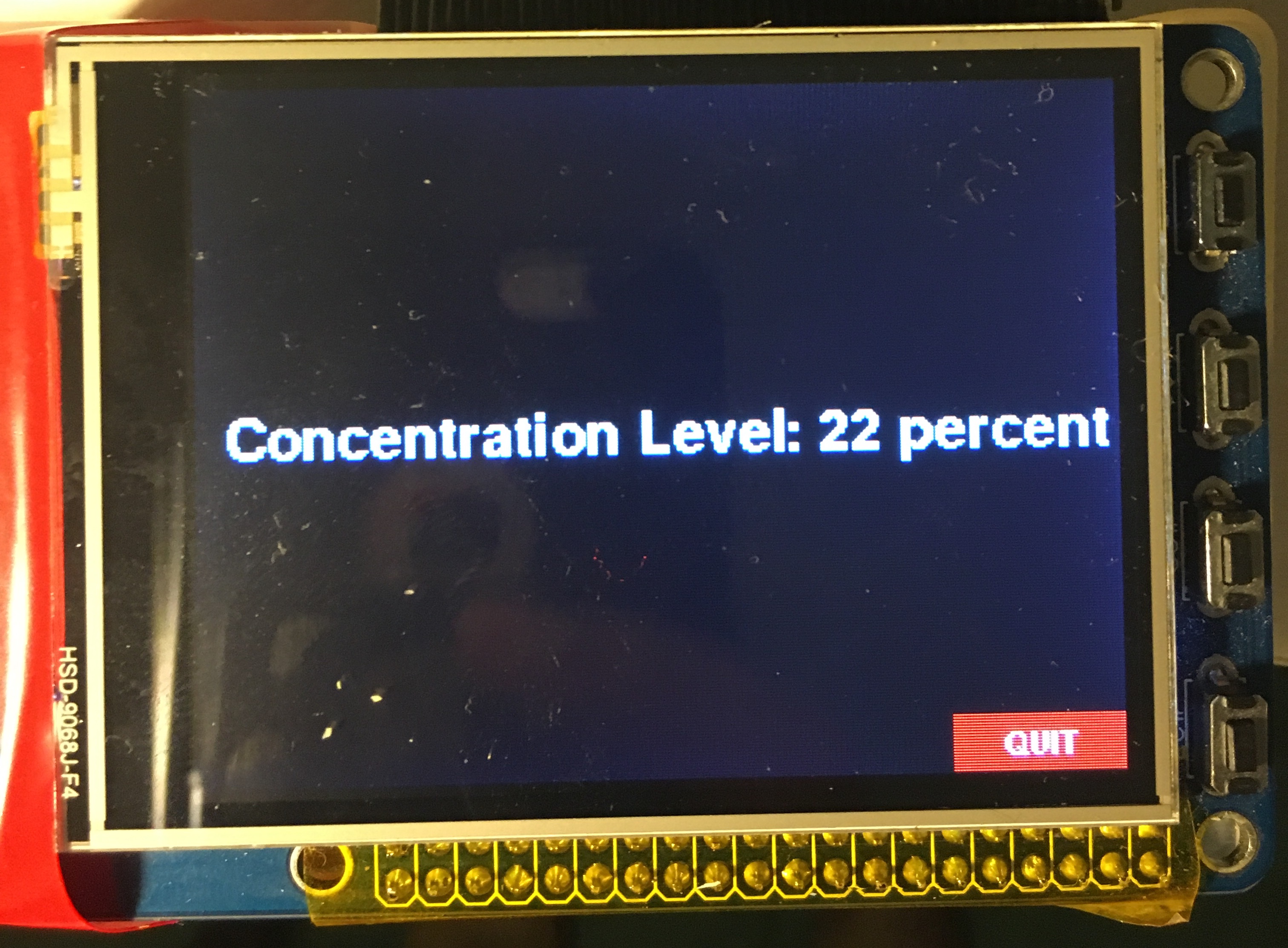
Fig 4: Screen displaying concentration level
GUI
The program starts as soon as the pi is powered up. So in order to make it easier for the user, we wanted them to be able to start the bot when they were ready. The start screen features two buttons that the user may use to either start the bot or to quit the application. In the event that the touch screen is in-operable, the user may use the physical buttons on the side of the pi TFT as well. Button #27 is to quit, while button #17 is to start. Once the user starts the robot, the default is for it to begin moving forward.
At this point we switch the GUI to display the current state of the user. We want the user to know their current attention level in order to help them focus, or unfocus, their thoughts in order to move the bot the speed they wish, so we print the attention percentage to the screen eery time it is updated. This also helps the user know which techniques to focus or distract themselves are working, such as focusing on the motion of the bot, doing math problems. or letting their mind wander. The quit button on screen is still available to exit the application, and the physical quit button, #27, still works in this mode as well.
Result
We were able to successfully use the users attention level for variable speed control of the robot, with a statistically significant degree of accuracy in using blinking to toggle the degree of freedom of the motion. Moving forward, we want to use the raw data to perform more accurate blink detection, potentially using machine learning to create a blink threshhold that is more accurate to the current user as they wear the headset, as opposed to the current method which employs a global threshhold for all users. We would also like to add in features that display the state of all 6 of the users brain waves. We would also potentially like to build a maze for wearers to move the bot through and perform a study on how effective the module could be for brain training.
Work Distribution

Seetha Kolli
sak295@cornell.edu
Data processing and GUI.

Mira Bhut
mab586@cornell.edu
Hardware, Bluetooth Protocols and Interfacing, Testing.
Parts List
- Raspberry Pi $35.00
- PiTFT touch screen $35.00
- MindFlex Headset - $17.00
- HC05 Bluetooth Module - 8.99
- LEDs, Resistors, Robotic testing platform and Wires - Provided in lab
Total: $99.50
References
BluezTower Pro Servo Datasheet
TGAM1 Spec Sheet
Instructables.com
mindwavemobile Library Bootstrap
Pigpio Library
R-Pi GPIO Document
Code Appendix
#!/ussr/bin/env python

""" MINDBOT.py :

HIGH LEVEL DESCRIPTION

Python script to stream data at 9600 Baud from wireless single channel
EEG DEVICE, Mindflex. MINDBOT.py performs fourier transform of streaming data for
feature extraction. It implements ML library PiScy to predict and classify EEG
signals with high accuracy. MINDBOT.py utilizes multi-processing python library for
efficiency.

RETURN AND OUTPUT

The python script will return and log all raw data points passed at 9600 BAUD in file EEG_RAW#
MINDBOT.py will also return and log all data points post feature extraction and classification.
Lastly, utilizing the processed and extracted data, MINDBOT will continously control GPIO pins
on Rasperry Pi for autonomous motor control of Mind controlled Robot. TFT Screen Implemented for
on board console.

LOW LEVEL DESCRIPTION

This is the implementation for multi-processing feedback controls
Based on the work of Xitang Xhao (xz522@cornell.edu) and Francis Yu (fy57@cornell.edu)
This model will use pipeline in which Master Process (stream raw data) is passed to Dual Master/Slave process to
filter data, removing noise and eye movement signals. It is then passed to 3 Slave Processes to compute respective
feature extraction and identification. These contours are then sent to master process queue to control Robot feedback.

                                                                        """

__authors__ = "Mira Bhut (MAB586) | Seetha Kolli (SAK295)"
__course__  = "Cornell ECE Embedded OS 5725 | Joe Skovira (JFS9)"

## Importing Libraries

## LIBRARIES                            ## FUNCTIONALITY
#from multiprocessing import Process, Queue, Valve, Lock, Array

import pygame                           #GUI for TFT Display     "
import os                               #RPI3 OS: LINUX          "
import time                             #TIME CONTROL/REF        "
import subprocess                       #ROUTINE SUB             "
import RPi.GPIO as GPIO                 #RPI3 GPIO Pins           "
import bluetooth                        #HC05 and RPI3 BT        "
import RawReader                        #BT COMMUNICATION BUFFER "
from MindflexDataPoints import RawDataPoint, AttentionDataPoint, EEGPowersDataPoint
from MindflexDataPointReader import MindflexDataPointReader


## CONNECT MINDFLEX BT, STREAM DATA FROM SINGLE EEG
mindflexDataPointReader = MindflexDataPointReader()             # CONNECT TO HC05
mindflexDataPointReader.start()                                 # START READER
dataPoint = mindflexDataPointReader.readNextDataPoint()         # READ NEXT BYTE

# ENVIRONMENT SETTINGS
os.putenv('SDL_VIDEODRIVER', 'fbcon')
os.putenv('SDL_FBDEV', '/dev/fb1')
os.putenv('SDL_MOUSEDRV', 'TSLIB')
os.putenv('SDL_MOUSEDEV', '/dev/input/touchscreen')

# INITIALIZE GPIOS
GPIO.setmode(GPIO.BCM)
GPIO.setup(27, GPIO.IN, pull_up_down = GPIO.PUD_UP)
GPIO.setup(17, GPIO.IN, pull_up_down = GPIO.PUD_UP)
GPIO.setwarnings(False)

# PYGAME SETTINGS
pygame.init()

#setting up screen
size = width, height = 320, 240
screen = pygame.display.set_mode(size)
pygame.mouse.set_visible(False)

#initialize fonts
pygame.font.init()
largeText = pygame.font.SysFont('Comic Sans MS', 30)
smallText = pygame.font.SysFont('Comic Sans MS', 15)

#initialize colors
black = (0, 0, 0)
white = (255, 255, 255)
red = (255, 0, 0)
green = (0, 255, 0)
blue = (0, 0, 255)

# Define buttons
quitSM_area = (185, 50, 60, 20)
quitGM_area = (260, 220, 60, 20)
start_area = (65, 50, 60, 20)
butt_width = 0

attn = 0  #data(2)

# render text
start = smallText.render("START", 0, black)
quit = smallText.render("QUIT", 0, white)
#conc = largeText.render("Concentration Level: %d" %conc_level, 0, white)

# define text location
start_loc = (80, 55)
quit_loc = (203, 55)
conc_loc = (10, 110)

# initialize game state variables
st = 0 # indicates game has started

pos = (0,0)

# MOTOR CONTROL PARAMETERS
period = 20
dc_stop = 0
freq = (1*1000)/period

dc_max = 0.2
dc_min = 0

blink = 0
oldSum = 0
countSum = 0
countUp = 0
#bl.theta = 0
#bl.lowAlpha = 0
#bl.highAlpha = 0
#bl.lowBeta = 0
#bl.highBeta = 0
#bl.lowGamma = 0
#bl.midGamma = 0

attn  = 0
ran = 100

#       SERVO1     #
# Pin13 as output PWM
GPIO.setup(13, GPIO.OUT)
servo1 = GPIO.PWM(13,freq)

#       SERVO2     #
# Pin19 as output PWM
GPIO.setup(19, GPIO.OUT)
servo2 = GPIO.PWM(19,freq)

# DEFINE BAILOUT CALLBACK ROUTINE
def GPIO27_callback(channel):
        global start_time
        GPIO.cleanup()
        start_time = -100

def GPIO17_callback(channel):
        global st
        if (~st):
                st = 1

# HELPER FUNCTIONS

def blinkDetect(data):

        global blink
        global oldSum
        global countSum

        #find sum of all wave values
        curSum = data.delta + data.theta + data.lowAlpha + data.highAlpha
        curSum = curSum + data.lowBeta + data.highBeta + data.lowGamma + data.midGamma

        if (countSum == 0):

                #find time average
                old_mean = curSum/(8)
        else:
                old_mean = oldSum/(8*countSum)

        cur_mean = curSum/8

        diff = cur_mean-old_mean

        #time.sleep(1.0)
        print"cur first then old"
        print cur_mean
        print old_mean
        #print countSum

thresh = 150000    ###set threshhold from testing
        if (abs(diff) >thresh):
                blink = 1
        else:
                blink = 0
                oldSum = oldSum + curSum
                countSum = countSum + 1

def startScreen ():   ## draw start screen ##
        global quit_butt
        global start_butt
        screen.fill(black)
        gameName = largeText.render("Mind Bot", 0, white)
        screen.blit(gameName, (110, 110))
        pygame.display.flip()
        quit_butt = pygame.draw.rect(screen, red, quitSM_area, butt_width)
        start_butt = pygame.draw.rect(screen, green, start_area, butt_width)
        screen.blit(start, start_loc)
        screen.blit(quit, quit_loc)
        pygame.display.update()

def updateStatus(con): #data(2)
        global quit_butt
        conc = largeText.render("Concentration Level: %d percent" %con, 0, white)
        screen.fill(black)
        screen.blit(conc, conc_loc)
        pygame.display.flip()
quit_butt = pygame.draw.rect(screen, red, quitGM_area, butt_width)
        screen.blit(quit, (278, 225))
        pygame.display.update()

def changeDir(val):     #change direction when user blinks
        global blink
        global dc2
        val = float(val)
        neg = -(dc2-7.5)
        dc2 =  7.5+neg
        servo2.ChangeDutyCycle(dc2)
        val = int (val)
        updateStatus(val)
        blink = 0

def runBot(val):        #change bot speed based on effort
        global dc1
        global dc2
        global countUp
        val = float(val)
        if (dc2>=7.5):
                dc2 = 7.5+val/100
        elif (dc2<7.5):
                dc2 = 7.5-val/100
        dc1 = 7.5+val/100

        val = int(val)

        if (countUp % 10 ==0):
                countUp = 0
                servo1.ChangeDutyCycle(dc1)
                servo2.ChangeDutyCycle(dc2)
                updateStatus(val)
                #print val
                #print dc1
                #print dc2
        else:
                countUp = countUp +1

def stopServos():       #Stop servos
        global cur1
        global cur2
        cur1 = 0
        cur2 = 0
        servo1.ChangeDutyCycle(cur1)
        servo2.ChangeDutyCycle(cur2)

# INITIATE SERVOS @ Forward
servo1.start(dc_stop)                                   # SERVO1 STARTS NEUTRAL
dc1 = 8.5                                        # CURRENT STATE: NEUTRAL
servo2.start(dc_stop)                                   # SERVO2 STARTS NEUTRAL
dc2 = 6.5                                          # CURRENT STATE: NEUTRAL

# set pins as callbacks
GPIO.add_event_detect(27, GPIO.FALLING, callback=GPIO27_callback, bouncetime=300)
GPIO.add_event_detect(17, GPIO.FALLING, callback=GPIO17_callback, bouncetime=300)

event = pygame.event.poll()

start_time = time.time()

startScreen()

while(time.time()-start_time <100):
        time.sleep(0.02)

        if(event.type == pygame.MOUSEBUTTONUP):
                pos = pygame.mouse.get_pos()
                if (start_butt.collidepoint(pos)):
                        pos = (0,0)
                        st = 1

                elif (quit_butt.collidepoint(pos)):
                        if(~st):
                                pos = (0,0)
                                GPIO.cleanup()
                                start_time = -100
                        elif(st):
                                pos = (0,0)
                                stopServos()
                                st=0
                                startScreen()
                                event=pygame.event.poll()
        if(st):
                time.sleep(0.2)
                dataPoint = mindflexDataPointReader.readNextDataPoint()  #read datapoint

                if (dataPoint.__class__ is AttentionDataPoint):   #if it is an attention value
                        attn = dataPoint.attentionValue   # get the attention value
                #       print attn
                elif (dataPoint.__class__ is EEGPowersDataPoint):       # if it is a blinkvalue
                        #print bl.delta         # get the blink value
                        bl = dataPoint

                        blinkDetect(bl)
                if (not dataPoint.__class__ is RawDataPoint):
                        print dataPoint
                if (blink):
                        print "you blinked"
                        changeDir(attn)         # uses attn because needs a servo speed after direction change, blink is global
                else:
                        runBot(attn)
                #if (not attn.__class__ is RawDataPoint):
                #       print attn
        event = pygame.event.poll()