ECE5725 Object Finding Robot
Qing Yu(qy95),Weiran Wang(ww463)
Demonstration Video
Project Objective
For our ECE 5725 Design with Embedded Operating Systems, our group designed a object-finding robot. The object-finding robot is able to find the different objects by colors and navigate to the detected target object. Our robot is also able to avoid obstacles during the navigation and arrive at the target object in a smooth motion.
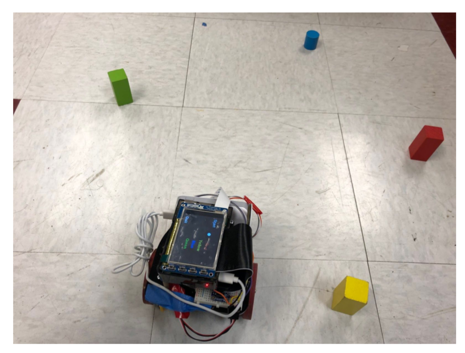
Figure 1 Object Finding Robot
Introduction
The object-finding robot is inspired by the situation that there are lots of color blindness people having trouble with finding objects with the exact color they want, such as clothes and accessories. We designed this color-based object finding robot to make their life easier. Generally, what the robot does is it looks for objects with the given color and marches to the object, there is a graphic user interface where users can simply choose the color by tapping piTFT touchscreen. At a high level, our project is based on a robot controlled by two parallax servo, Raspberry Pi serves as the brain of the robot. By processing the inputs from Pi Camera and Infrared sensors, the robot is able to recognize different colors, navigate to the target color object, and avoid obstacles during the navigation.
Hardware Design
Overall Design
The hardware design of our robot consists of a Raspberry Pi, Pi camera, pololu infrared distance sensors, pi TFT, two servo motors, and front dowel. Two servos are used to control the motion of the robot through GPIO output. Pi Camera, mounted at the front, is used to capture images for future color identification. Infrared sensors, mounted at left and right sides, are implemented to avoid obstacles when the robot running towards the target. The power bank serves as power supply for the Raspberry Pi, 4 AA battery batteries are used to power the servos.
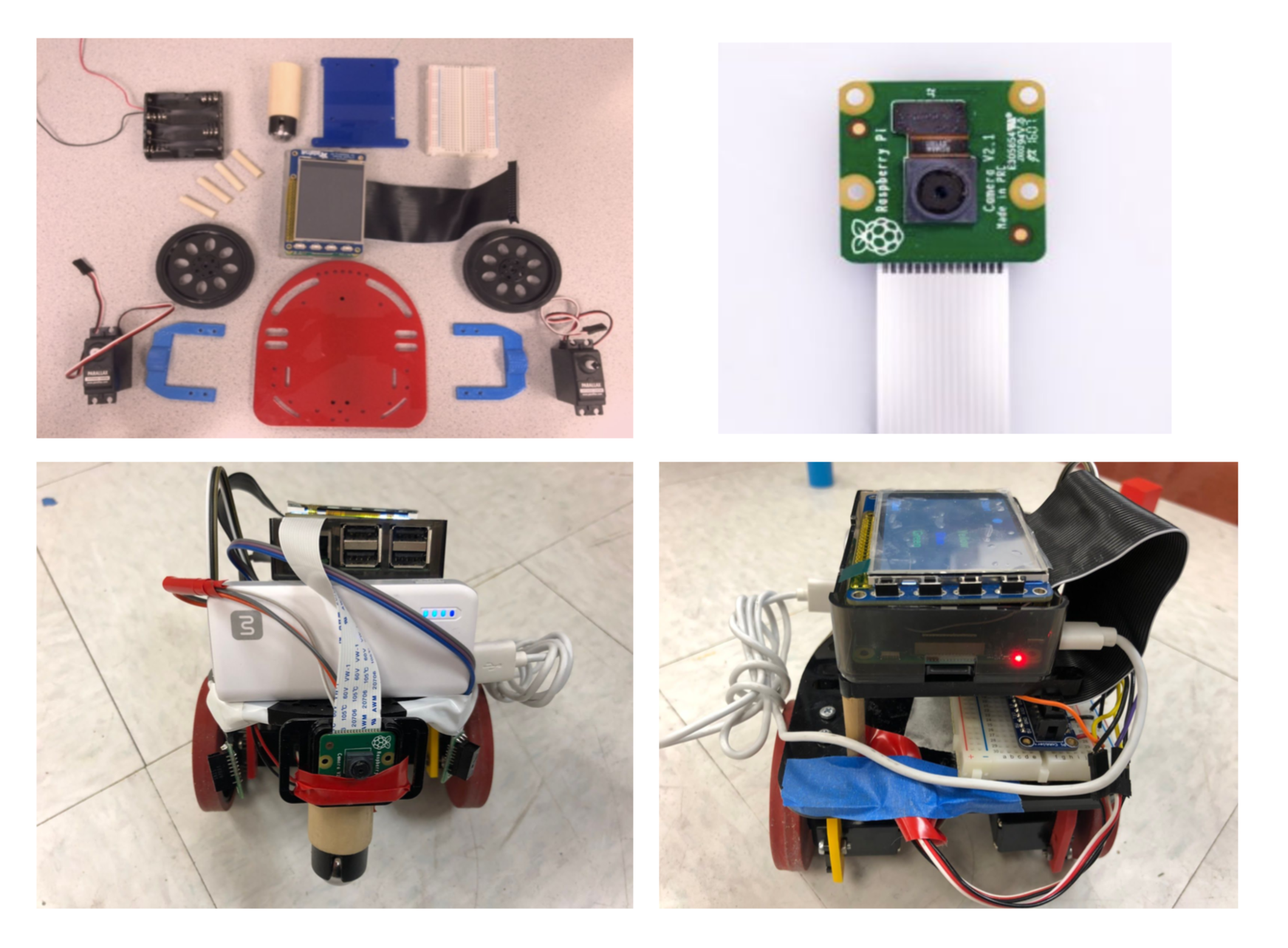
Figure 2 Robot Hardware
Pololu IR Distance Sensor
The infrared sensors we used is from pololu. This small digital distance sensor detects objects between 2 cm and 10 cm away. It is composed of an integrated combination of PD (photo diode) , IRED (infrared emitting diode) and signal processing circuit. Two IR distance sensors are wired to Raspberry Pi GPIO ports. Obstacles are detected when the output of the IR sensor is low and the red emitting diode lights up which is easy to observe for users. As we can see above, two infrared sensors are placed on the two sides at an angle of 45 degrees to the front. Upon doing several tests, this is the best place for the sensors to successfully detect obstacles and avoid crashing into obstacles.
Parallax Servo
We wired two servo to Raspberry Pi GPIO 5 and GPIO 6. As specified on the datasheet of parallax servo, we first need to generate a signal with 1.5ms pulse refreshed every 20ms to calibrate the servo. The reason for setting up the pulse to 1.5ms is because this is the value in the ‘center’ of the range(1.3ms-1.7ms) that the servo will accept, 1.7 ms is all the way left and 1.3 is all the way right. Given the value in the datasheet we compute the duty cycle ranging from 6.04% to 7.90% to achieve full speed clockwise and anti-clockwise rotation. To verify that the signal generated by Rpi is correct we use an oscilloscope and measure the signal pulse width and period making sure it is correct. However, when we test the servo rotation, it’s not quite satisfactory because the PWM signal generated by software is not very stable and the wheels shake a lot, so we decided to switch to hardware pwm on the Raspberry Pi, since hardware pwm can only be generated from GPIO 12 and 13, we rewired servo motors to GPIO 12 and 13. The servo motors are powered by 4 AA batteries and we also added a switch to better control the servo. To use hardware PWM with python, simply import pigpio library and set up frequency and duty cycle.
Software Design
Basic Logic
In the software section, the team used Python with Pi Camera and OpenCV library to detect the objects’ colors and navigate the robot toward the target. We installed the OpenCV library to scan the environment and detect the selected color object. After the selected object is detected, the logic to navigate the robot towards the selected object is to always put the object in the center frame while the robot is moving. To let the robot move smoothly without swaying left and right, we added a PID control algorithm to make the robot running quite straightforward to the target object. The logic flow chart is shown below.
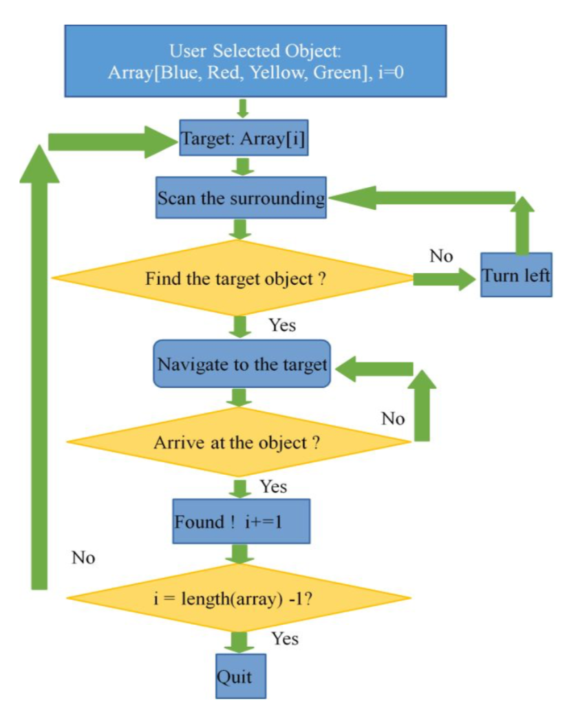
Figure 3 Logic Flow chart
Object Detection
For object detection, our group used OpenCV library to detect the largest selected color object viewed by Pi Camera and get that coordinated location in pixels. To install the OpenCV library, we run the command line (sudo apt-get install libopencv-dev python-opencv).
First, the group used function cv2.VideoCapture() to capture real-time video with Pi camera and set the size of the image using function camera.set(). Then the team read in what the camera captured using the camera.read() function and save it in a variable named image.
To better make the image detecting different colors, the team changed the image from BGR to HSV using function cv2.cvtColor(image,cv2.COLOR_BGR2HSV). Not as BGR, which range all the colors value by how blue, how green, and how red, HSV range the colors by Hue, Saturation and Value. Hue gave us an essential color (red, yellow, green, blue), Saturation gave us the intensity of color and Value gave us the overall brightness of the pixel. By using HSV, the team can easily determine an essential color range by adjusting Hue value. The team used cv2.inRange() function to make a mask on the object within the selected color range.
To find the reddest color object, for instance, we first used cv2.findContours() to find out the contours of the red object and for loop all the contours to find out the reddest color object.
To extract the coordinate of reddest color object, we used cv2.moments() to get the coordinate and format it to a integer value (target_x, target_y). We used this target_x value to make the decision whether the object is on the left or on the right of the robot. Then the team drew a circle with crossing lines to mark the reddest area. And used that area information to make the decision how close the target object is for the robot. The processed images are shown below.
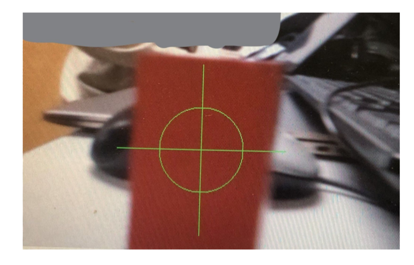
Figure 4 Object Detection Marks
PID Control
The team used PID control algorithm to make the robot running smoothly and straightly towards the target object. Since PID is a feedback control loop algorithm, the feedback for our PID is the difference between the x_axis of the reddest color, for instance, and the x_axis of the center coordinate, which can be obtained by half of the image width (X_diff = abs(target_x-center_x)).
Proportional Control is proportional to the X_diff. If the difference between the target and the center is large, the robot should turn in a quicker speed to make the difference between them smaller. Similarly, the robot should relatively turn in a slower speed when the difference is close to a predefined range.
Derivative Control is used to control the speed for the target_x getting closer to the center_x. By using the derivative control, the robot was less easy to get overshoot comparing to just using Proportional Control. In order to obtain the speed for target_x approaching center_x, the team used time.time() function to record the previous time and current time. We also defined a variable prevX_diff to record the previous difference.
Integral Control can help the movement more stable. It accumulates the X_diff and when the error decreases, the proportional effect will be eliminated by this integral control, which prevents the overshoot.
To obtain the overall control strength, we multiply them by their relative coefficiency kp, kd, ki, and sum them up (strength = Propor_x*kp + Deriv_x*kd + Integral_x*ki). The strength was passed to move_control() function to adjust the duty cycle of hardware PWM and control the servo rotation speed and direction.
The condition for controlling robot turning left or right is determined by the target_x value. If the target_x is within the center_x +- 80, then it can just move forward. If the target_x is smaller than the range, the robot should turn left and if the target_x is bigger than the range, the robot should turn right.
Pygame User Interface
To better interact with users, we developed a graphic user interface which makes the robot easy to use. Once the robot boots up, the user interface pops up as we can see on the piTFT screen. There are 6 buttons displayed on it, to use the robot, users can simply tap colors they want to look for on the screen and press start button, then the robot starts to find objects with the given colors in sequence. The white dot on the screen indicates what color the robot is currently looking for, the position of the white dot changes as the color changes, when it’s done the user can quit the program by pressing ‘Quit’ button on the display. We think the user interface is especially important for our project because we aim to design the robot that everyone can use with on effort. The intuitive touch screen and graphic feedback make the robot much easier to use.
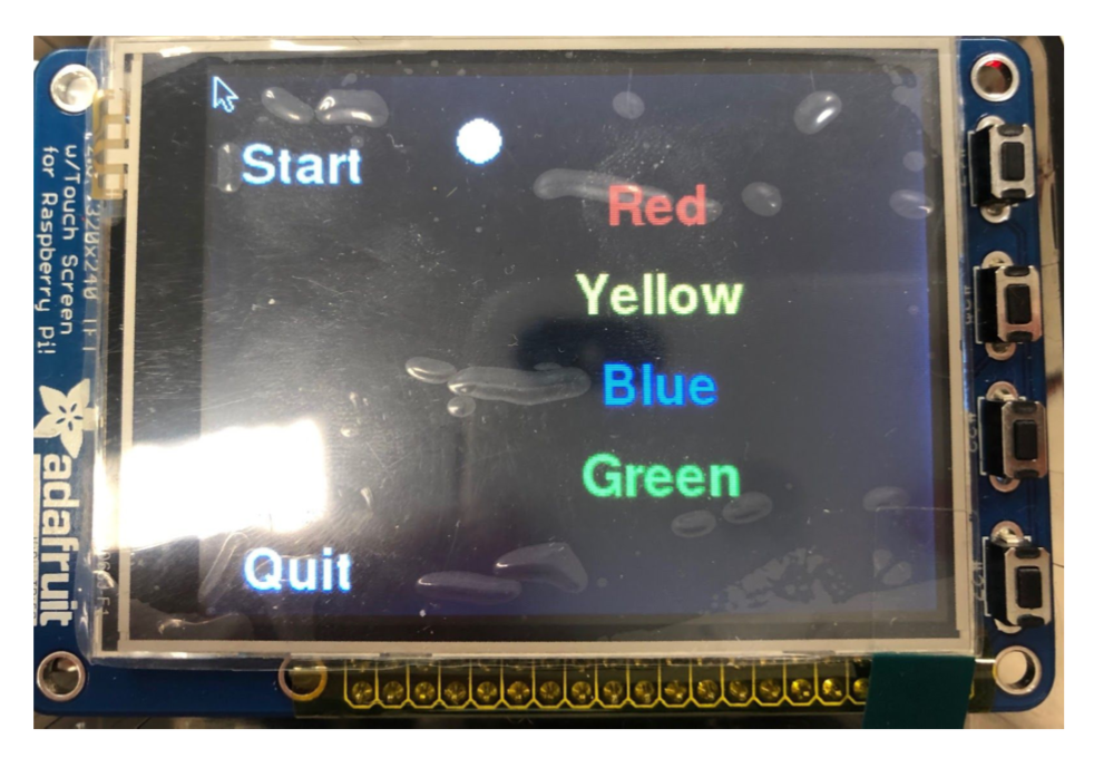
Figure 5 Graphic User Interface
Testing
PiCamera
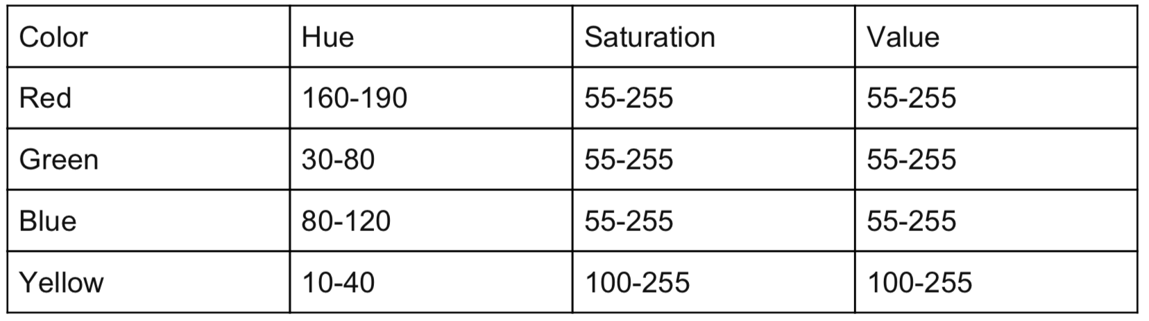
To use Pi Camera to do color identification, we’ve been testing the images captured by Pi Camera and see how the colors will be interpreted in HSV scale. Rather than using traditional RGB model, HSV gives us better color identification results. HSV stands for hue, saturation and value. Hue is the color portion of the color model, expressed as a number from 0 to 360 degrees, saturation is the amount of gray in the color. Reducing the saturation toward zero to introduce more gray produces a faded effect. Value works in conjunction with saturation and describes the brightness or intensity of the color. Initially, we set the range of red, yellow, blue and green according to HSV color chart, but it does not perform very well due to the change of ambient light and pi camera shooting angle. So we tested the range HSV values while the pi camera is shooting on different colors. Finally. we set up the range of different colors as follows:
Table 1 Selected Color Range in HSV
To test whether the coordinates viewed by camera correspond to the actual position of object for the robot, the team conduct several tested to display the image captured by the camera on the screen, print out the current position whether on the left or on the right of the robot, and validate with the object’s actual position compare to the robot.
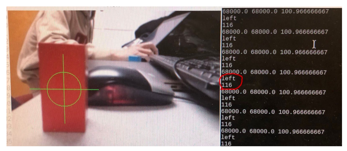
Figure 6 Object Location
Form the picture above, we can see that the red object is located at the left of the screen. From the control console, we verified that by printing out its position which is left and also the distance the object is from the center which is 116 pixels (The width is 480 pixels and the height is 320 pixels).
Robot Motion
The basic logic for the robot to navigate to the target object is putting the object within the center frame range. However, since there are slight differences between the two wheels, the robot cannot go absolutely straight. Also, since the camera extracted the reddest area of that target object in the real-time, during the robot movement, it is possible that the camera extracted different reddest area. In these situations, the robot performance without using PID control was below our expectation. The robot kept swayed between left and right, and easily lost the target object if it overshot.
After adding the PID control, the team started to adjust the coefficient of proportional control kp, Integral control ki, and derivative control kd. To simplify the whole adjusting process, the team first adjust kp to enable the robot to change directions if it is out of the center range. Based on our testing, if kp is too large, there is great overshoot when the robot changed directions, and if it is too small, it seems like it cannot turn to the center range. Then the team adjusted kd to control the speed that the robot change direction, the value of kd is usually set small because if the speed is too fast, the possibility of overshooting is also large. Finally, we adjust ki to be relatively small and we wanted to apply the PID control when the X_diff is in a reasonable range. Otherwise, it is possible that the target object is out of the screen.
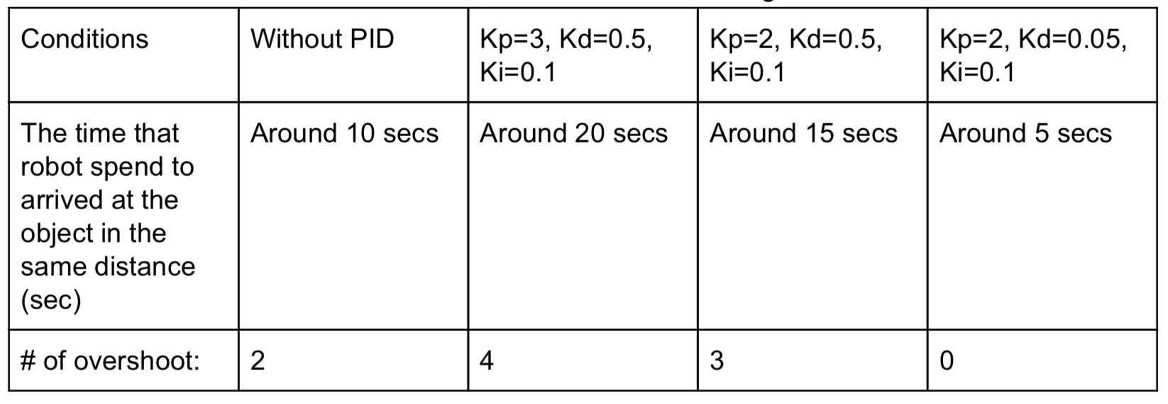
The team conducted the testing to adjust three coefficients by recording the time that from the robot started finding a color object to finally arrived at the robot.
Table 2 PID Coefficient Testing
Result
Our object-finding robot successfully achieved the following goals as designed:
The robot can scan ambient objects and identify different colors such as red, yellow, blue, green accurately with front pi camera.
The navigation and the motion of the robot when approaching to the object with given colors are smooth and straightforward after we implement hardware PWM and PID control algorithm to the system and program.
The robot is able to avoid obstacles with front infrared sensors when running to the target. When obstacle is detected, depending on the position of the obstacle, the robot can automatically backup and make a turn away from the position of the obstacles and start looking for target again.
The robot has an intuitive graphical user interface which allows user to choose colors by pressing the corresponding text button, initiates the robot by pressing start button, and quit the program by pressing quit button.
Future Improvement
Due to the time limitation, there are many aspects and future works that can be done to further enhance our robot. Despite the accurate color identification using openCV library, we still experienced latency with the object tracking and color identification, if we had more time, we would think about processing images with multiprocessing library which could decrease latency to a large extent.
Moreover, another issue we ran into was the lack of accuracy of motion control. Even though we implemented hardware pwm and PID algorithm on the servo, the movement of the robot is not as smooth as we imagined. The accuracy of the motion can largely influence object tracking and color detection.To improve motion control, we can further adjust parameter in PID algorithm.
In addition, the user interface can be further improved, for example, the number of objects detected in each color can be displayed on the screen. We can also provide more color options for the user and optimize the logic of the GUI.
Work Distribution
Work Distribution:
Qing Yu:
Pi Camera implementation, PID control algorithm, Color detection with Pi Camera, Servo control algorithm, Obstacle avoidance algorithm, Report and website
Weiran Wang:
Robot Assembly, Hardware PWM algorithm, Infrared sensors implementation, Servo control algorithm, pygame user interface, Report and website
Project group picture
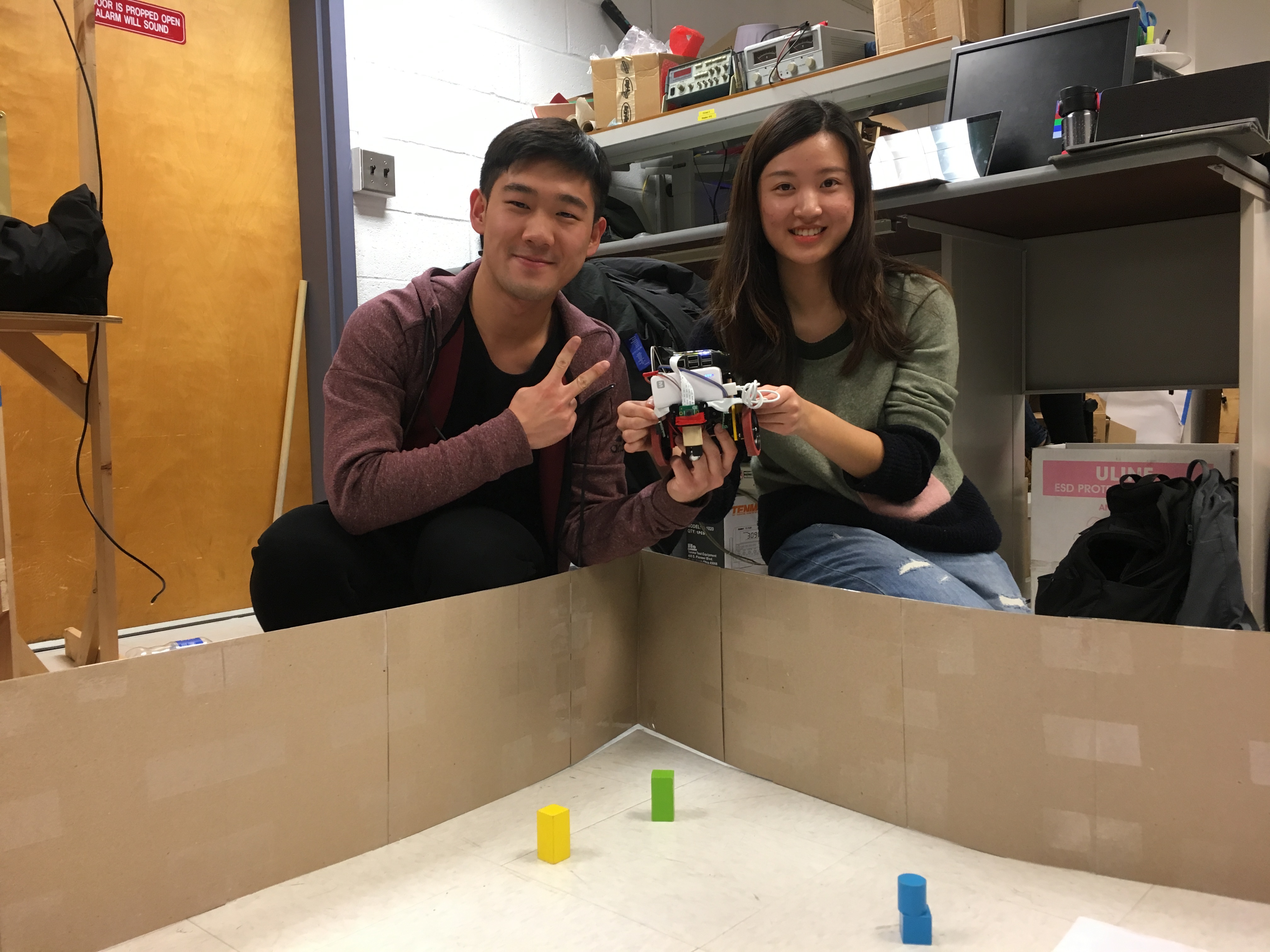
WeiRan Wang (ww463), Qing Yu (qy95)
ww463@cornell.edu
qy95@cornell.edu
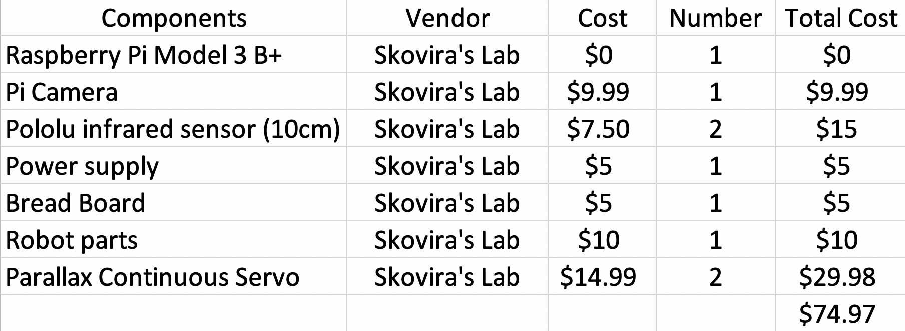
Project Cost
References
OpenCV with PythonConcept for Color detection
OpenCV and PiCamera
Pigpio Library
R-Pi GPIO Document
Code Appendix
# Qing Yu (qy95), Weiran Wang (ww463)
# ECE 5725 Final Project: Object Finding Robot
# 12/5/2018

# Basic Description
# objFinding_code.py detect different objects by colors,
# after locating the target object, the robot navigates to the target object
# when the robot is close to object, the robot will stop and backward meaning
# that the robot finished finding current object and start to find next.
# two IR sensors on the left and right sides of the robot help the robot to avoid obstacles.

# GUI User explaination
# User pressed the colors buttons want to find serialsly on the PiTFT
# Then pressed start button to let the robot start finding selected-color object
# Press Quit button to quit the program.

# import libraries
import os
import time
# This system command loads the right drivers for the Raspberry Pi camera
os.system('sudo modprobe bcm2835-v4l2')
#enable the touch screen on PiTFT
os.system('sudo rmmod stmpe_ts')
os.system('sudo modprobe stmpe_ts')
time.sleep(0.1)
import numpy as np
import cv2
import pigpio
import RPi.GPIO as GPIO
import pygame
from pygame.locals import*

# load the program to PiTFT and enable the mouse
os.putenv('SDL_VIDEODRIVER', 'fbcon')
os.putenv('SDL_FBDEV', '/dev/fb1')
os.putenv('SDL_MOUSEDRV', 'TSLIB')
os.putenv('SDL_MOUSEDEV', '/dev/input/touchscreen')
pygame.init()

#display the mouse on the PiTFT touch screen
pygame.mouse.set_visible(True)

#set up the GPIO
GPIO.setmode(GPIO.BCM)
#setup for IR sensor
GPIO.setup(26, GPIO.IN)
GPIO.setup(19,GPIO.IN)
GPIO.setup(16,GPIO.IN)
# set up a bail out button to bail out from the PiTFT
GPIO.setup(27,GPIO.IN, pull_up_down=GPIO.PUD_UP)
#set up hardware PWM
pi_hw = pigpio.pi()
pi_hw.hardware_PWM(12, 46.3, 69700)
pi_hw.hardware_PWM(13, 46.3, 69700)

# define the array for saving different color object
objectColor = []

#set up the width and height for the pi camera window
w=480
h=320
center = w/2

# enable and set up the camera
my_camera = cv2.VideoCapture(0)
my_camera.set(3,w)
my_camera.set(4,h)
time.sleep(2)

#define global variables for servo speed
quater_speed_counter = 71000.0
half_speed_counter = 72000.0
full_speed_counter = 79000.0
quater_speed_clk = 68000.0
half_speed_clk = 66000.0
full_speed_clk = 60400.0

#define global variable for storing current color range
lower_color = np.array([0,0,0])
upper_color = np.array([0,0,0])

#define the variable for servo calibration
currMovement_left = 69700.0
currMovement_right = 69700.0

#define the global variable for left and right direction
#set them to '' at first
leftDir=''
rightDir=''

# define two value to record the target object's coordinates
target_x=0
target_y=0

# define variables for GUI Pygame display
size = width,height = 320,240
white = 255,255,255
global screen
global main_font
screen = pygame.display.set_mode(size)
main_font = pygame.font.Font(None,35)

finish = 1 # flag variable used to control the main while loop
finishType = 1 # flag indicating whether the user finished selecting colors
index = 0 # indicate the which color object is currently looking for
count=0 # indicate whether it is the first time in the loop


# function for servo to change direciton based on selected speed
def direction(servo,dir):
    global quater_speed_counter, quater_speed_clk
    if servo == 'p_left':
        if dir == "clockwise":
            pi_hw.hardware_PWM(12, 46.5, quater_speed_clk)
        elif dir=="counter-clockwise":
            pi_hw.hardware_PWM(12, 46.3, quater_speed_counter)
        else:
            pi_hw.hardware_PWM(12, 0, 0)
    else:
        if dir == "clockwise":
            pi_hw.hardware_PWM(13, 46.5, quater_speed_clk)
        elif dir=="counter-clockwise":
            pi_hw.hardware_PWM(13, 46.3, quater_speed_counter)
        else:
            pi_hw.hardware_PWM(13, 0, 0)

# function to let the robot turn right
def turn_right():
    direction('p_right', "counter-clockwise")
    direction('p_left', "counter-clockwise")
# function to let the robot turn left
def turn_left():
    direction('p_left', "clockwise")
    direction('p_right', "clockwise")
# function to let the robot move forward
def forward():
    direction('p_left', "counter-clockwise")
    direction('p_right', "clockwise")
# function to let the robot move backward
def backward():
    direction('p_left', "clockwise")
    direction('p_right', "counter-clockwise")
# function to let the robot stop
def stop():
    direction('p_left', "stop")
    direction('p_right', "stop")


# PID control value using with move_control function
# The function is used for doing the movement adjustment
def move_control(leftDir,rightDir,strength):
    global currMovement_left,currMovement_right, quater_speed_counter, quater_speed_clk
    # Calculate the value for the speed increment each time
    increment = (quater_speed_counter-quater_speed_clk)/100.0
    # if the left wheel should do clockwise motion
    if leftDir == 'clockwise':
        #calculate the current Movement value for left wheel
        currMovement_left = currMovement_left-strength*increment
        # set the current movement value to the smallest value it could be
        #if it is smaller than the largest duty cycle
        if (currMovement_left<quater_speed_clk):
            currMovement_left = quater_speed_clk
    # if the left wheel should do counter clockwise motion
    elif leftDir == 'counter-clockwise':
        #calculate the current Movement value for left wheel
        currMovement_left = currMovement_left+strength*increment
        # set the current movement value to the largest value it could be
        #if it is bigger than the largest duty cycle
        if (currMovement_left>quater_speed_counter):
            currMovement_left = quater_speed_counter
    # if the right wheel should do clockwise motion
    if rightDir == 'clockwise':
        #calculate the current movement value for right wheel
        currMovement_right = currMovement_right-strength*increment
        # set the current movement value to the smallest value it could be
        #if it is smaller than the largest duty cycle
        if (currMovement_right<quater_speed_clk):
            currMovement_right = quater_speed_clk
    # if the right wheel should do counter clockwise motion
    elif rightDir == 'counter-clockwise':
        #calculate the current movement value for right wheel
        currMovement_right = currMovement_right+strength*increment
        # set the current movement value to the largest value it could be
        #if it is larger than the largest duty cycle
        if (currMovement_right>quater_speed_counter):
            currMovement_right = quater_speed_counter
    # update the new value to Hardware PWM and change the servos speed
    pi_hw.hardware_PWM(12, 46.3, currMovement_left)
    pi_hw.hardware_PWM(13, 46.3, currMovement_right)
    #print currMovement_left, currMovement_right, strength


# function used to define different colors' lower and upper threshold
# update the global variable lower_color and upper_color to the current color value
def currentColor(cur_color):
    global lower_color, upper_color
    #define color range for red
    lower_red = np.array([160,55,55])
    upper_red = np.array([190,255,255])
    #define color range for green
    lower_green = np.array([30,55,55])
    upper_green = np.array([80,255,255])
    #define color range for blue
    lower_blue = np.array([80, 55, 55])
    upper_blue = np.array([120,255,255])
    #define color range for yellow
    lower_yellow = np.array([10,100,100])
    upper_yellow = np.array([40,255,255])
    # update the global variable lower_color
    # and upper_color to the current color value
    if cur_color == 'red':
        lower_color = lower_red
        upper_color = upper_red
    if cur_color == 'green':
        lower_color = lower_green
        upper_color = upper_green
    if cur_color == 'yellow':
        lower_color = lower_yellow
        upper_color = upper_yellow
    if cur_color == 'blue':
        lower_color = lower_blue
        upper_color = upper_blue

# function to display Pygame on the PiTFT screen
def GUI(circle_pos):
    #define different color variable
    black = 0,0,0
    red = 255,0,0
    green = 0,255,0
    yellow = 255,255,0
    blue = 0,0,255
    # fill the screen black
    screen.fill(black)
    # write the red button
    red_text = main_font.render('Red', True, red)
    red_rect = red_text.get_rect(center = (200,60))
    screen.blit(red_text,red_rect)
    # write the yellow button
    yellow_text = main_font.render('Yellow', True, yellow)
    yellow_rect = yellow_text.get_rect(center = (200,100))
    screen.blit(yellow_text,yellow_rect)
    # write the blue button
    blue_text = main_font.render('Blue', True, blue)
    blue_rect = blue_text.get_rect(center = (200,140))
    screen.blit(blue_text,blue_rect)
    # write the green button
    green_text = main_font.render('Green', True, green)
    green_rect = green_text.get_rect(center = (200,180))
    screen.blit(green_text,green_rect)
    # write the circle indicator
    circle_rect = pygame.draw.circle(screen, green, circle_pos, 10)
    # write the start button
    start_text = main_font.render('Start', True, white)
    start_rect = start_text.get_rect(center = (40,40))
    screen.blit(start_text,start_rect)
    # write the quit button
    quit_text = main_font.render('Quit', True, white)
    quit_rect = quit_text.get_rect(center = (40,220))
    screen.blit(quit_text,quit_rect)
    # display the screen on the real screen
    pygame.display.flip()

# function used to avoid the right obstacles
def avoid_right():
    print "avoid right"
    stop()
    time.sleep(1)
    backward()
    time.sleep(1)
    turn_left()
    time.sleep(1)
    forward()
    time.sleep(5)
# function used to avoid the left obstacles
def avoid_left():
    stop()
    time.sleep(1)
    backward()
    time.sleep(1)
    turn_right()
    time.sleep(1)
    forward()
    time.sleep(5)

# The first stage of the program is to detect the touch screen inputs
while finish:
    time.sleep(0.1)
    # bail out function
    #(use GPIO 27 as the button to quit the program if sth goes bad)
    if (not GPIO.input(27)):
        print(" ")
        print "Quit (bail out)"
        break
    # display the initial GUI
    if count == 0:
        GUI([120,30])
        count=1
    # detecting whether the touch screen has been energized
    for event in pygame.event.get():
        pos = pygame.mouse.get_pos()
        x,y = pos
        if (event.type is MOUSEBUTTONDOWN):
            pos = pygame.mouse.get_pos()
            x,y = pos
        # the touchscreen is pressed
        elif(event.type is MOUSEBUTTONUP):
            pos = pygame.mouse.get_pos()
            x,y = pos
            # append the string of different colors in the object Color array
            # if relative color button is pressed
            if y>50 and y< 80 and x>170:
                #print ("red")
                objectColor.append('red')
            if y> 90 and y<120 and x>170:
                #print ("yellow")
                objectColor.append('yellow')
            if y>130 and y<160 and x>170:
                #print ("blue")
                objectColor.append('blue')
            if y>170 and y<200 and x>170:
                #print ("green")
                objectColor.append('green')
            # quit the program when the user pressed quit
            if y>200 and x<100:
                #print ("quit")
                finish=0
                break
            # start the robot when the user pressed start
            if y<50 and x<60: #start
                finishType = 0
                #print ("start")

    # The second stage of program is to loop through the object Color array until the last color
    while (index<len(objectColor) and not finishType):
        # Set up local variable x_diff, prevX_diff, and Integral_x
        x_diff = 0
        prevX_diff = 0
        Integral_x = 0
        start_time = 0
        # bail out function
        #(use GPIO 27 as the button to quit the program if sth goes bad)
        if (not GPIO.input(27)):
            print(" ")
            print "Quit (bail out)"
            break
        # store the current looking color in cur_color
        cur_color = objectColor[index]
        # call the function to get the corresponding color lower and upper bond
        currentColor(cur_color)
        #print cur_color
        # display and move the white dot to the corresponding color button
        if cur_color == 'red':
            GUI([120,60])
        elif cur_color == 'blue':
            GUI([120,140])
        elif cur_color == 'green':
            GUI([120,180])
        else:
            GUI([120,100])
        # increment the looping index
        index+=1

        # The third stage of program is to detect object and navigate to the object
        while 1:
            # bail out function
            #(use GPIO 27 as the button to quit the program if sth goes bad)
            if (not GPIO.input(27)):
                print(" ")
                print "Quit (bail out)"
                break
            #reading the value of IR sensor to see if it is close to obstacles
            sensor_center = GPIO.input(26)
            sensor_left = GPIO.input(19)
            sensor_right = GPIO.input(16)
            # call avoid_left function when left sensor energized
            if sensor_left==0:
                avoid_left()
                print "IR_left"
            # call avoid_right function when right sensor energized
            elif sensor_right==0:
                avoid_right()
                print "IR_right"
            # read the image from camera
            success, image = my_camera.read()
            # flip the image if it is upside down
            image = cv2.flip(image,-1)
            # change the image from BGR to HSV
            image_HSV = cv2.cvtColor(image,cv2.COLOR_BGR2HSV)
            # set the mask with selected color's lower and upper bond range
            mask = cv2.inRange(image_HSV,lower_color,upper_color)
            # findContours returns a list of the outlines of the white shapes in the mask (and a hierarchy that we shall ignore)
            contours, hierarchy = cv2.findContours(mask,cv2.RETR_TREE,cv2.CHAIN_APPROX_SIMPLE)
            # If we have at least one contour, look through each one and pick the biggest
            diam = 0
            if len(contours)>0:
                largest = 0
                area = 0
                for i in range(len(contours)):
                    # get the area of the ith contour
                    temp_area = cv2.contourArea(contours[i])
                    # if it is the biggest we have seen, keep it
                    if temp_area>area:
                        area=temp_area
                        largest = i
                # Compute the x coordinate of the center of the largest contour
                coordinates = cv2.moments(contours[largest])
                target_x = int(coordinates['m10']/coordinates['m00'])
                target_y = int(coordinates['m01']/coordinates['m00'])
                # Pick a suitable diameter for our target (grows with the contour)
                diam = int(np.sqrt(area)/4)
                # draw on a target
                cv2.circle(image,(target_x,target_y),diam,(0,255,0),1)
                cv2.line(image,(target_x-2*diam,target_y),(target_x+2*diam,target_y),(0,255,0),1)
                cv2.line(image,(target_x,target_y-2*diam),(target_x,target_y+2*diam),(0,255,0),1)

            # show the image
            # cv2.imshow('View',image)

            # when the robot is close to the target
            # the robot will stop and backward for 1 second
            if (diam > 60 and target_y < 240):
                stop()
                time.sleep(2)
                #print "close to object: stop"
                backward()
                time.sleep(1)
                #print "close to object: back"
                stop()
                time.sleep(1)
                #print "close to object: stop"
                break

            else:
                # control motor to move and check the target
                # if the target is found
                if (diam>3):
                    # calculate the error difference between the target_x and center
                    x_diff = abs(target_x-center)
                    #print x_diff
                    # define PID coefficients
                    kp = 2
                    kd = 0.005
                    ki = 0.1
                    # calculate the proportional, Derivative, and Integral Control
                    Propor_x = x_diff/(w/2.0)
                    Deriv_x = (prevX_diff - x_diff)/(time.time() - start_time)
                    Integral_x += x_diff
                    # update the start time
                    start_time = time.time()
                    # reset the integral value if it is too big or too small
                    if Integral_x<0:
                      Intrgral_x = 0
                    elif Integral_x>1000:
                      Integral_x = 1000
                    # calculate the final strength for PID control
                    strength = Propor_x*kp + Deriv_x*kd + Integral_x*ki

                    # Conditions when the target is on the left of the robot
                    if (target_x < w/2-100):
                        leftDir = "clockwise"
                        rightDir = "clockwise"
                        move_control(leftDir,rightDir,strength)
                        #print "left"
                    # Conditions when the target is on the right of the robot
                    elif (target_x > w/2+100):
                        leftDir = "counter-clockwise"
                        rightDir = "counter-clockwise"
                        move_control(leftDir,rightDir,strength)
                        #print "right"
                    # Conditions when the target is in the center range
                    else:
                        forward()
                        #print "center"

                # turn left to circle around to find the target color
                else:
                    pi_hw.hardware_PWM(13, 46.5, 70500)
                    #print "not in the screen"

                # update the prevX_diff value
                prevX_diff = x_diff
            # Esc key to stop, otherwise repeat after 33 milliseconds
            #key_pressed = cv2.waitKey(1)
            #if key_pressed == 27:
            #   break

# clean up the GPIO and Hardware PWM and release the camera
GPIO.cleanup()
stop()
pi_hw.stop()
cv2.destroyAllWindows()
my_camera.release()
#cv2.waitKey(10)