ECE 5725 | Final Project
SLAM Clean Robot
Junyi Shen js3439, Peng Wu pw444
DEC. 2018
Introduction
In this project, we aimed to building up an autonomous indoor clean robot. Firstly, it will use odometry and distance information to construct indoor environment by SLAM algorithm. Then, it will combine the color information with shape information to recognize cans as our test trash. With pixel value in the image, it could transfer them into world coordination. At last, it will visit these trash.
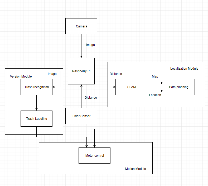
Figure 1: Overall Design for the Project
Objective
Building an autonomous clean robot with these functions:
[1] Simultaneous localization and mapping(SLAM)
[2] Image recognition and coordination mapping
[3] Dynamic Control
Design & Testing
System Setup
For this section, we will briefly introduce some sensors and software libraries we used for our project. Actually, we met many issues to use these materials, so we will fairly evaluate their advantages and disadvantsges according to our experience.
1. Camera
For our project, we choose Pi camera V2 to capture the images. Although you may meet some problems to install the drive for usage, but you could find many good software materials and libraries to support this camera. However, sometimes it is so fragile that tiny destruction could induce image distortion. Feel free to choose USB-based camera, which is also easy to install and has higher transfering speed.
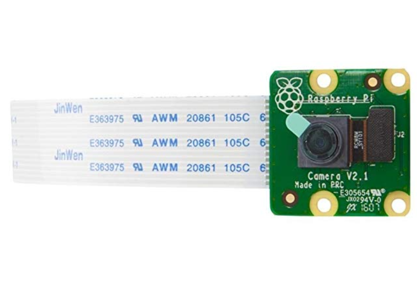
Figure 2:Pi Camera
2. Rangefinder
Actually, there are many kinds of rangefinders for purchase online, including lidar, IR, sonar, etc. The category and price of rangefinders are up to the requirements for distance range, resolution and error tolerance. For our project, we choosed a mini "lidar" sensor, actually an IR sensor to detect the distance produced by Benewake Company. The range of distance is 0.3 to 12 meters with UART. Due to the UART pins are used for bluetooth by default, so we used TTL-USB converter for convenience.
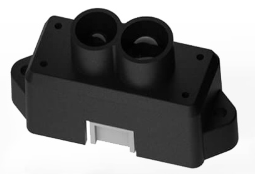
Figure 3:TFmini lidar
3. Motors
The choices for motors are important for dynamic control. For our project, we have tried two kinds of motors, one is parallax servo for LAB3 and another is DC motors. Parallax servo could directly accept the PWM input from Raspiberry Pi while DC motors should be connected with DC motor controller. Actually, due to sensetive to the currency, DC motors' output could be more unstable than others resulting in harder dynamic control. In addition, most control libraries are written by Python not by C or C++ which were used by our porject. So, we offer some general code for motor control using wiringPi library referring to our code link.
4. Encoder
Encoder is a simple method to evaluate odometry information of robot based on the distance of two wheels. It consists of sensors and disks. Sensor could produce pulses by photodetector and code disks determine the resolution. However, for certain cases, the rotation of wheels is not equal to the real displacement. Electronic compass or gyro are also good choices for position and orientation evaluation.
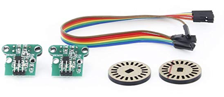
Figure 4:Encoder
5. Boost & Eigen3
Boost and Eigen3 are awesome libraries for C/C++ programming. For our project, Boost library is used for serial communication and pointer management, the later of which is also supported by C++11. You could also use wiringPi to read and write serial data. In addition, the Eigen3 library produce overall API for sentific calculation, especially for matrix, vector and possibilities. In order to compress the file size for compiling, we just extract the functions we need from eigen3 into the seperated files.
SLAM
This section will introduce the bsic procedure for SLAM algorithm. Actually, there are different kinds of SLAM algorithms for different situations based on different data fusion. For our project, we used distance infomation to ensure the edges and odometry information to resample the particles. However, due to the high complexity of the algorithm and limited computation ability of Raspberry Pi. We gave up simultaneous data collection and calculation but generated the final map afterwards.
Data Collection
Distance data collected by rangefinder are transfered through USB connector. By boost asio package, we could easily get the raw data and extract the distance infomation. Through lsusb command, we could get the list of usb devices. Based on the device name, use stty command to obtain the baud rate. Then we could analyze the message according to pattern. We use vector to store the history records and flush them into the log file for calculation.
Map Construction
Same with newcomers to be fimiliar with the enviroment, just observe around by eyes. In this project, the rangefinder just works as eyes, with robot rotation to observe the new surrounding. However, because robot could receive inaccurate data during collection, observation from multi positions and angles could help robot to make sure which are the edges with the highest probability. Particle filter is an amazing tool to solve this issue, which could be devided into two sections, prediction and filtering. Prediction stage will calculate the best edges of the map based on all history while filtering stage will replace the particles with lower scores by higher ones.
Based on the paper we referref to, different with simple method, which evaluate the next pose of robot by motion model and odometry input. We will fisrt use previous particles and distance input to guess the optimal pose of robot. If failed, then we will use motion model to do the same task. Afterwards, we will re-calculate the importance of different particles and update the map.
Resample is an important procedure for particle filter, which will eliminate the points with low weight. But we don't need to resample for each iteration. We referred to the arugument of N_eff, which could be calulated as follows.
This argument can be regarded as a measure of the dispersion of the importance weights, so it could be a useful measure to evaluate how well the particle set approximates the target posterior. If it drops below the threshold, resample will begin.
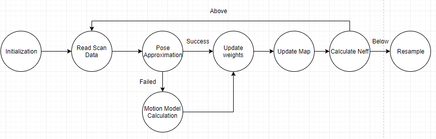
Figure 5:SLAM algorithm diagram
Testing
Our SLAM algorithm accepts the log file as input. It would analyze the content of file and get the data. Every 180 records would be viewed a group of data for a single iteration with the odometry information of robot. Following figures demonstrates the simulation results and real results for demo.

Figure 6:Map under simulation(circle environment)

Figure 7:Map for demo(rectangle environment)
Dynamic
This section introduces how to control the motion of robot. As metioned before, we tried two kinds of motors, including parallax motors and DC motors. We would introduce them seperately.
Parallax Motor
Parallax motors were used for Lab3, which just accepts PWM to control the rotation speed and direction. The interval of pulses is 20ms and the middle value for pulse duration is 1.5ms. The range of duration is from 1.3ms to 1.7ms. Differnet with python PWM library to set up duty cycle and frequency, we should set up the sleep time duration for different pin value outputs by wiringPi library. In order to set up different sleep time for two motors, we used multi-thread library of standard C++ library. We could transfer the reference of pulse duration into the threads. Thus, everytime we changed the relative value in main thread could influence the status of motion thread. Here is the simple example for motion control.
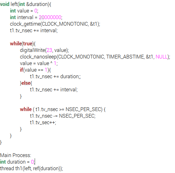
Figure 8:Example code for motion control
DC Motor
DC motors are controlled by the value of currency or the voltage of input. It is driven by DC motor driver which accepts PWM to determine the rotation speed and voltage difference to determine the rotation direction. Based on the dc motor driver manual, it has contributed a library for python to use. However, because our project is based on C/C++, we could choose to embed the python lib into the C code or program another C library, which is still under test during our exploration.
Robot Motion Control
For our project, we use FSM to determine the present status of robot and corresponding motion. The FSM diagram is illustrated as follows:
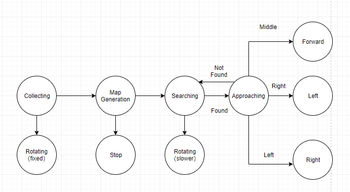
Figure 9:SLAM algorithm diagram
Image recognition
To realize image recognition, we integrate both color detection with shape detection for the sake of accuracy. For color detection, we apply HSV (hue, saturation, lightness) model on the image analysis. For preparation stage, we set up the simulated environment (150cm*150cm made by cardboard) and stablized the camera on the robot for consistant image data collection. Place the target object randomly in the designed environment. Change both positions of the robot and the object while recording position images. We collected 300 pictures with or without the object from different angles. Find the range of each parameters (HSV) using photoshop. Notice that the HSV values in photoshop are different from those in opencv HSV libary. Thus measured values are needed to be converted as following:
H(opencv)=H(ps)/2;
S(opencv)=S(ps)*255;
V(opencv)=V(ps)*255;
In the code, we import the original image first and identify the interest areas based on range variations of each HSV parameter (first stage). By applying HSV library in opencv, processed image will be polarized which means it is in black and white (black means non-interested areas and white shows area of interest). Resulted image after first stage shown as below.
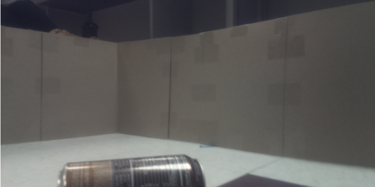
Figure 10:Original image
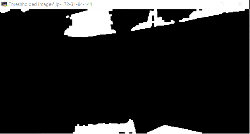
Figure 11:Output image after first stage
As shown in the output image, there are areas marked in white which are not the position of the target object. One reason is because the lighting cause the HSV values fall between selected ranges. The other reason is because there are contexts in the image that have similar color to the interested object. In the second stage, we continue the shape detection on the output image. Using contour function in opencv draws the best fit rectangles on all the potential objects. Notice that the function requires at least four coordinates of points that each of two can establish a parallel line with the other two. Applying this function itself does help to filter out areas with irregular shapes. Next step is to calculate the areas of the rectangles and filter out those with unreasonalbe values (especially extremely large ones). Then check the coordinates of the remaining rectangles. Eliminate those ones locate on the very top of the image because of the height of the cardboard. Exported the the image with remaining rectangles as shown below.
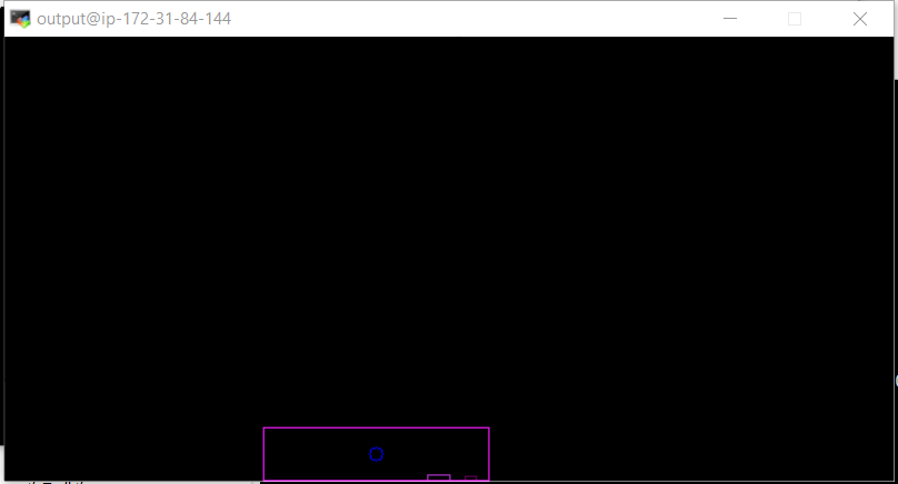
Figure 12:Output image after second stage
The center of the contour is also marked. If the program detects the object in the original image, the coordinates of the center will be printed out. If no object is detected, center position will be exported as (-1,-1).
Results
Finally, we have completed most of tasks as expected. As for SLAM algorithm, due to imprecise odometry approximation, there is a little shift for each detection iteration. However, we could basicly protrait the shape of simple environment. As for image recognition, we could use color recognition and various filters to recognize the can in the vesion field. For dynamic control, our wheeled robot could rotate with configed angular speed and correctly switch among different statuses.
Conclusion
For this final project, we took advantages of many algorithms in various areas and tried many methods to optimize the performance. It is a challenging task and we met many obstacles during the exploration. But, we learned how to integrate the knowledge from different aspect into a signle robot to complete complex tasks. It is an really awesome experience for both of us.
Future Work
In fact, we will optimize these parts in the future wrok.
[1] Replace encoder with gyro to calculate the position and orientation of robot.
[2] Optimize the SLAM algorithm, especially the calculation complexity and large map construction.
[3] Adopt other image recognition methods to recognize different kinds of trash and decrease the sensivity to the light
[4] Implemet path planning algorithm based on the combination between map and trash location
Work Distribution
| Peng Wu | Junyi Shen |
| SLAM | Image Recognition |
| Dynamic Control | Environment construction |
| Final Report | Final Report |
Expense
| Item | Cost |
| Raspi Camera V2 | $25.00 |
| TFMini Lidar Sensor | $35.00 |
| TTL-USB Converter | $10.00 |
| Sum | $70.00 |
Code Appendix
We have upload all of our code into github, you could refer to this link:
Reference
[1]Giorgio Grisetti, Cyrill Stachniss, and Wolfram Burgard: Improved Techniques for Grid Mapping with Rao-Blackwellized Particle Filters, IEEE Transactions on Robotics, Volume 23, pages 34-46, 2007
[2]Boost C++ library: https://www.boost.org/
[3]Opencv library: https://opencv.org/
[4]Eigen3 library: https://eigen.tuxfamily.org/dox/
[5]C++11 multi threading: https://solarianprogrammer.com/2011/12/16/cpp-11-thread-tutorial/