Automatic Number Plate Recognition System
Designed By
Xinyue Zhou (xz677), Jingyi Hu (jh2677)
Demonstration Video
Introduction
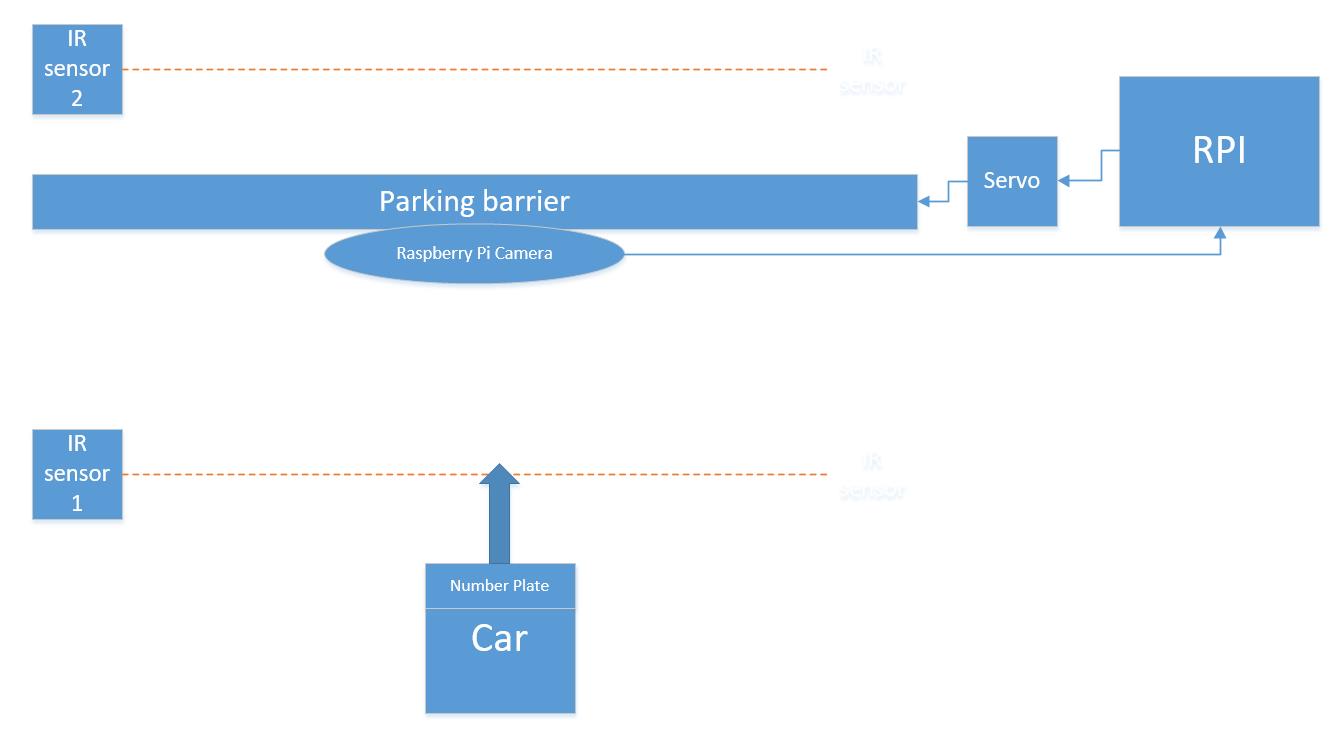
Our project aims to design a parking barrier modeling system with automatic number plate recognition.In our project, we used two Raspberry Pi. One for controlling the car stuck with printed number plate to move linearly toward the barrier and stop if it is not allowed to enter. The other is for controlling two Infrared IR sensors to trigger camera and servo respectively, and for image processing and recognition. The whole parking system runs as shown in the figure below: when the car moves close to the barrier within a certain distance, a sensor will react and transfer a signal to the RPi. Then, RPi will control the camera to take a photo, and processing the image get from Rpi camera using openCV and transfer individual number or letter images to a sequence of characters using OCR so that the input number plate can be checked whether matched the stored number plates string in “database”. After processing with OCR, the number plate will be recognized by RPi, then displayed on the PiTFT. If it matches with the number plates in the if-statement we set before, the barrier will lift up to let the car in, or the car will be barriered out. After the car passes through the barrier and reaches a certain distance, another sensor behind the barrier will react and transfer a signal to RPi. And RPi will control the barrier to lift down.
Objective
- Raspberry Pi camera configure and control
- Image processing including number plate localization, background remove, character enhancement, noise remove and skew correction
- OCR recognition
- IR sensors configure and control
- Standard servo configure and control with barrier
- Pygame display
- Car control
The general idea is that several car number plates are prestored, meaning car with these number plates are allowed to enter the park (barrier will open) while other number plates not matched the system “database” will not be allowed entering (barrier keeps closed). Additionally, the car moves automatically with changeable number plates to demonstrate the whole function of the system.
Design & Testing
- Big Picture
- Hardware design
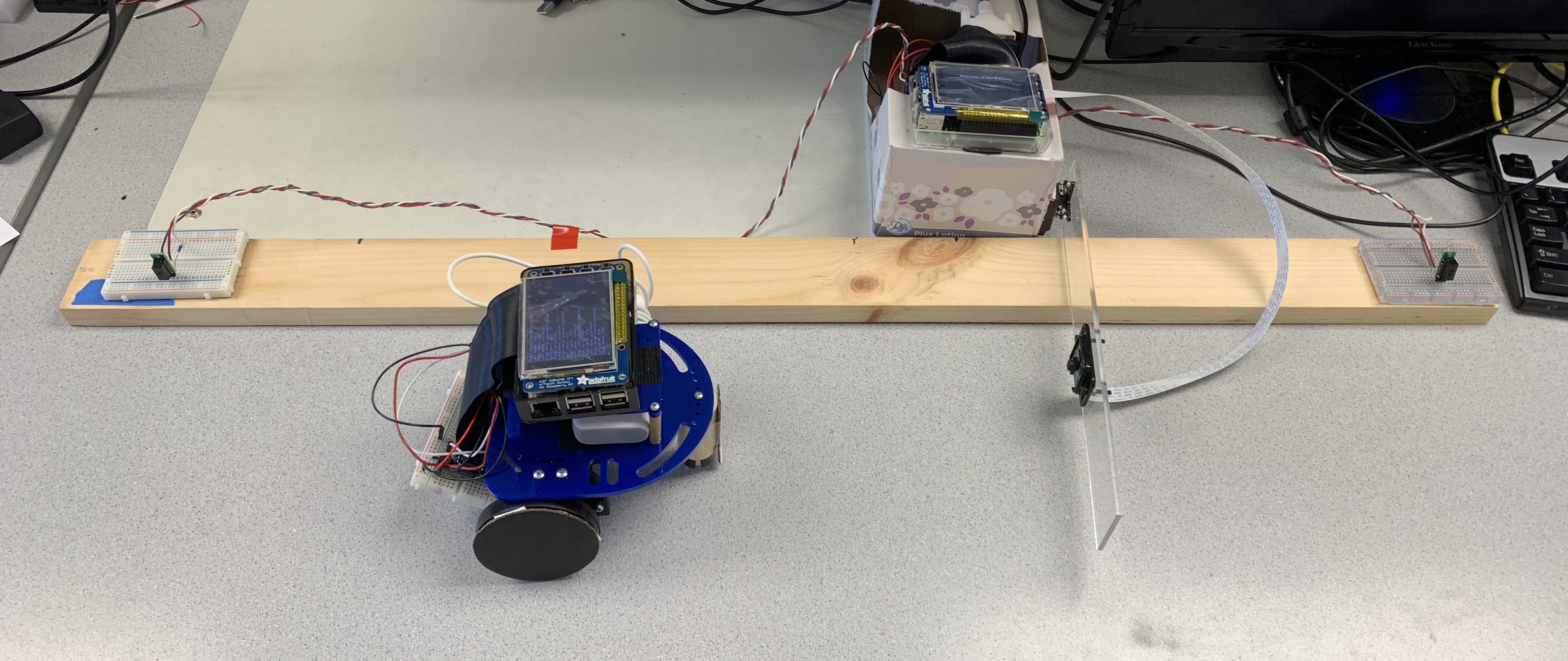
The hardware design of our parking system consists of two Raspberry Pi, a station, a barrier, two IR sensors , a modeling car and a camera. We first started with building the fundamental subsystem composed of a RPi, a camera, two IR sensors and a servo which is used to control the barrier.
For the camera, we connected it with RPi using a cable with proper length.
For IR sensors, We used GP2Y0D810Z0F, which is a distance measuring sensor to detects objects between 2 cm and 10 cm (0.8″ and 4″) away, composed of an integrated combination of PD (photo diode), IRED (infrared emitting diode) and signal processing circuit.For proper installation and use, we first soldered the pin portion and main sensor portion together, then, connected them with RPi respectively. Among three pins of each sensor, the left one needs to be grounded. The middle pin should be connected to the power supply (3V3 output on RPi), while the right one should be connected to a 1k resistance, then to GPIO to provide control signal. We chose GPIO19 and GPIO26 respectively as input pin since they are free available. When the sensor not detecting any object it input a high signal (“1”) into Pi, while once it detect an object a low signal (“0”) will be imported.
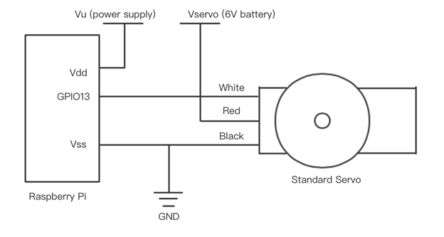
As For the servo, we used Parallax Standard Servo (#900-00005) because it is controlled by position rather than impulse time while encoding, and it can hold any position between 0 and 180 degrees.In our project, we needed the barrier lifted 90-degree up and lifted down to the initial position. Thus, the standard servo satisfied our expectation, and the quick-start circuit shows as below (using GPIO13 as output to control the servo) :
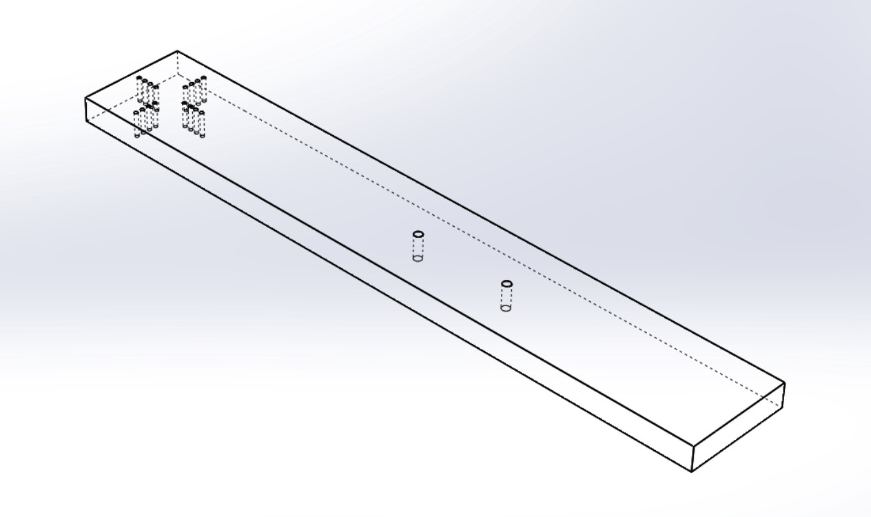
Besides the above subsystem, we also made a barrier using Cast Acrylic material and laser cut technology. Cast Acrylic is a thermosetting plastic with a superior surface finish, flatness and optical properties. It is also a hard and brittle material which is sensitive to stress concentrations. This is most evident if parts are small or thin, thus is proper to be made into a barrier. And we chose laser cutting mainly because of its easier workholding and reduced contamination of workpiece (since there is no cutting edge which can become contaminated by the material or contaminate the material). Precision may be better, since the laser beam does not wear during the process. There is also a reduced chance of warping the material that is being cut, as laser systems have a small heat-affected zone.Based on these, we designed a barrier model in CAD, which is 25cm long, drilling holes in the middle to fix camera, and also drilling holes on the one side to be connected with servo, as shown in the following figure:
Then, we designed a station to integrate the above parts into a whole. We used a paper box to accommodate battery with carrier, power bank and breadboard, and stuck the PiTFT on the top of the box to make the display clear to be seen. In addition, we used a plank to fix the position of two IR sensors and the paper box. Since the speed of the car is almost fixed, and the time cost of image processing and recognition will not vary significantly, we can determine the distance from the first sensor to the paper box to ensure enough time for RPi to analyze and control servo. In the same way, we can also determine the distance from the paper box to the second sensor to guarantee the whole car to pass through before the barrier lifts down.
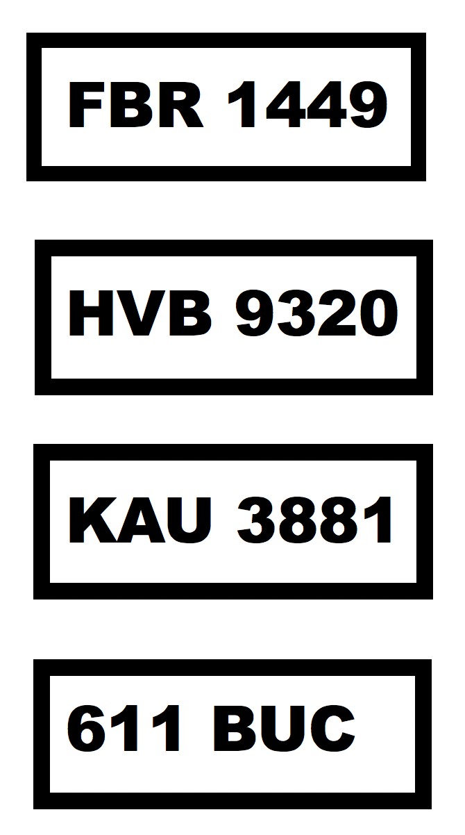
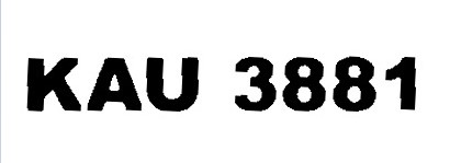
As for the car, we used the one we assembled in previous lab. And we printed four different number plates with bold font and bold border for easier localization and recognition as follows:
To make the car move linearly, we attached a second Raspberry Pi on it and connected them with two Parallax Continuous Rotation Servos (#900-00008). The quick-start circuit is same as standard servo (we chose GPIO12 and GPIO13 as output of control signal), while the difference is that continuous rotation servo is controlled by impulse time.We used hardware PWM method to control two servos since they are not exactly same, it is inconvenient to set frequency or duty cycle to make them rotate with same speed. Therefore, we just gave same calibrate signals to these two servos, and used a screwdriver to adjust the rotation speeds as consistent as possible.
- Software design
Image capture use Raspberry Pi Camera
- After Raspberry Pi Camera was assembled and configured on the Pi, python code can be written to control the camera. First of all, PiCamera library need to be imported and initialized:
from picamera import PiCamera
camera = PiCamera()
- In addition, camera settings such as resolution, framerate, brightness, and rotation can be adjusted according to condition.
- Then, preview on monitor and image capture can be done by using
camera.start_preview() sleep(2) camera.capture('image.jpg') camera.stop_preview()- It should be noticed that, before image capture at least 2 seconds sleep time has to be introduced to give the sensor time to set its light levels. Also, camera preview only works when a monitor is connected to the Pi, so remote access (such as SSH and VNC) will not allow you to see the camera preview.
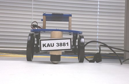
Image processing
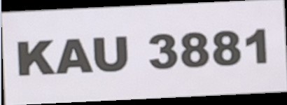
- After image captured by pi camera, we need to process the image including number plate localization, background remove, noise remove, character enhancement and skew correction. In process result is shown as four figures below.
- To do these image processing in python code, opencv module is required. Therefore, we first install opencv on raspberry pi by running command:
sudo apt-get install libopencv-dev python-opencv
- Then use
import cv2to import opencv module into python code. - Detailed steps to process the image can be explained using the pseudo code below:
- number plate localization, background remove
Read in captured image;
Change RGB to grayscale;
Noise removal with iterative bilateral filter(removes noise while preserving edges);
Histogram equalisation for better results;
Morphological opening with a rectangular structure element;
Image subtraction(Subtracting the Morphed image from the histogram equalised Image);
Thresholding the image;
Applying Canny Edge detection;
Dilation to strengthen the edges;
Finding Contours in the image based on edges;
Creating the kernel for dilation;
Finding Contours in the image based on edges;
Sort the contours based on area;
Loop over our contours:
    Approximate the contour with 6% error;
    Select the contour with 4 corners as the number plate’s counter;
Obtain the 4 corner position, achieve number plate localization;
Masking the background as black background
Segment the number plate region from the whole image according to 4 corner coordinates;

- Character enhancement and noise revoment
Thresholding the segmented grayscale  image again to black and white;
Created a structuring elements as kernel;
Morphological opening(erosion followed by dilation) with a rectangular structure element to remove noise;
- Skew correction
Flip the foreground and background to ensure foreground is now "white" and the background is "black";
Grab the (x, y) coordinates of all pixel values that are greater than zero;
Compute a rotated bounding box that contains all coordinates;
Obtained the rectangle rotating angle (in range [-90,0)) using cv2.minAreaRect();
If rectangle rotates clockwise add 90 degrees to the angle;
else  just take the inverse of the angle to make it positive;
Rotate the image matrix according to the angle obtained above
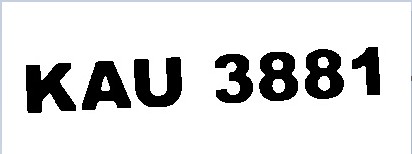
After above image processing steps, the result image is like following figure shown and is clear enough to be passed for recognition. Therefore, the aim of image processing achieved.
Number plate recognition
In this project, Optical Character Recognition(OCR) engine was used for recognition, that is transfer the characters in image to text. In this way we can check whether the character on number plate is same as the one stored in database to decide whether it is an legal number plate allowing entrance.
In order to use the OCR engine, we first installed the open source tesseract-ocr package which contains OCR engine -libtesseract and command line program -tesseract by running:
sudo apt-get install tesseract-ocr
After that, we can use command line in format below to run tesseract for image recognition:
tesseract imagename outputbase [-l lang] [--oem ocrenginemode] [--psm pagesegmode] [configfiles...]
In this project we used command line below to recognize image processed result “output2.jpg” and store the recognition result into “file.txt” with specifying the language as english and page segmentation modes as treat the image as a single text line:
tesseract output2.jpg file -l eng -psm 7
Then, result in txt file can be read out for following logical control.
Logical control and display using pygame
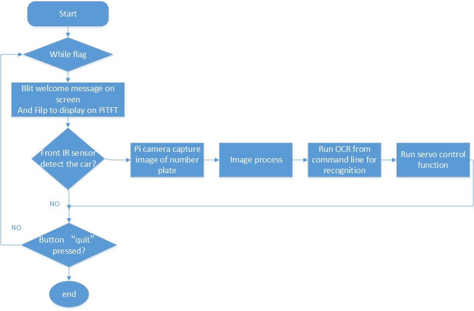
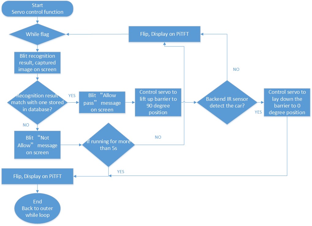
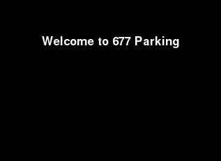
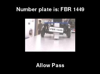
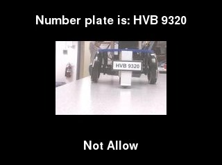
The whole system logic is that when the front end IR sensor detect the car it will trigger the pi camera to take a photo and then Raspberry pi process the image and user OCR engine to recognize the number plate and then check the recognition result with those stored in database, if the number plate matched with one in database, this is a legal number plate, servo will be controlled to lift up parking barrier to allow car entrance. At the same time, the recognition result will be displayed using pygame on PiTFT as well as the image that captured by pi camera and a message said “Allow pass”. And then, when car leaving and detected by the second IR sensor, servo will be triggered to lay down the barrier and now the system welcomes the next car coming for check with PiTFT displaying a welcome screen. However, if the recognized result was found that this is an illegal number plate, then the servo will be controlled to not lift up the barrier, and on PiTFT, instead an allowance message but a message said “Not allow” will be displayed so that “driver” need to stop the car and leave. After wait for a few seconds, the whole system welcomes the next car coming for check.
Python to achieve above whole system logic can be demonstrated by the two logic flow chart below:
The first chart is the logic flow chart for whole system outer while loop
The second one is logic flow chart for servo control function inner while loop
Hardware PWM for servo
- In order to get more stable signal, we decide to use hardware PWM method to both control the standard servo and continuous rotation servos.
- After import pigpio library, we setup piTFT buttons for broadcom numbering first. Then, connect to pi gpio daemon:
pi_hw=pigpio.pi()
- For the standard servo, it is controlled by position. According to the datasheet, we set the initial place at 0.00225 by code below:
pi_hw.hardware_PWM(13,f,dc)
- 13 stands for GPIO13, used as PWM output. f is frequency, equaling 1/(0.00225+0.02) since the servo needs to receive a pulse every 20 ms in order to hold its position. And dc is duty cycle, equaling (0.00225/(0.00225+0.02))*1000000.
- When the car with legal number plate comes nearly, the servo should drive the barrier to lift up to 90 degree. It can be realized by setting the position at 0.00125, thus the frequency and duty cycle also change, controlling the servo to hold almost 90-degree position. In the similar way, just set the position at 0.00225 to control the servo to lift down after car passing. It should be noticed that after each time setting a new position, frequency and duty cycle should be both set to zero to initialize the servo, making it ready for receiving next position signal.
- For continuous rotation servos, we choose GPIO12 and GPIO13 as PWM outputs respectively. The controlling code is same as above.
- Noticed that we should run command
sudo pigpiodbefore running python codes in order to launch the pigpio library as a daemon and use it correctly.
Issues & Solutions
- Reduce image processing time
In this project, in order to have more accurate recognition result, we set the resolution of pi camera to a relatively large value 2592*1944, but this will cause the image processing time become long (13s). Our solution to this problem is to segment the image into smaller one containing the number plate after image capture but before image processing. This method is feasible because position of numblate on car is fixed, position of camera on barrier is also fixed, hence the position of number plate on the captured image is also relatively settled. And this method can reduce the image processing time to around 5s.
- Run OCR engine for recognition
- At the testing stage of this project we imported ocr pytesseract module in order to run ocr engine in python code.
- We install it by running:
sudo pip install pytesseract
- And applying it in python file by using:
from PIL import Image import pytesseract im=image.open("image.jpg") text=pytesseract.image_to_string(im, lang='eng')- This module works well when we not use “sudo” to run this file. However, after we added pygame part and want to use “sudo” to execute the python code to display on PiTFT, an error message shows no pytesseract library. We assume this is due to under the admin access it cannot find the path to this library. Therefore, we came back to the original method to run ocr engine using command line, store the result to file and then read it from the file for following process. To run this command line from python code we import subprocess:
import subprocess
cmd="tesseract output2.jpg file -l eng -psm 7"
print subprocess.check_output(cmd, shell=True)
- In this way, this python code can be executed by “sudo”. And this solution is inspired by the idea in 2018 spring project “The Eye”.
- Make car running linearly
In order to run the car linear, we at first apply symmetric duty cycle to GPIO12 and GPIO13 to get PWM. However, even though the hardware PWM signal is stable, two servo rotating with different speed due to these two servo is not identical. And because we want to run the car at low speed, the servo speed is highly affected by hardware condition of servo, hence, if we use software to adjust the duty cycle to achieve approximate same speed of two servo, this point can easily changed when restart the servos. Therefore, we finally decided to use hardware PWM to provide stable calibration signal (high pause 1.5ms), and use screwdriver to calibrate the two servo to approximately same speed. This method is more efficient than calibrating using software.
Results
We were successfully able to meet all our intended goals for the Automatic Number Plate Recognition system. After running car-control python code and adjustment by screwdriver, the car can move almost linearly towards the barrier with proper speed. The first IR sensor will trigger the camera to take a photo which will be processed by RPi through following steps: number plate localization, background remove, character enhancement, noise remove and skew correction. Then, the result image will be recognized and changed into a text. We prepared four different printed number plates for testing. Two of them are prestored (FBR 1449 and KAU 3881), while the other two are illegal (HBV9320 and 611 BUC). If the text content is consistent with a number plate we prestored before, the barrier will be lifted up, which means that the car with this number plate is allowed to pass. In the meanwhile, the text content after recognition, the initial photo taken by camera, and indication words (‘Allow Pass’) will be displayed on the PiTFT. After that, the car keeps moving and reaches the second IR sensor, triggering the barrier to be lifted down. If the text after recognition is not consistent with any in the prestored ‘database’, the barrier keeps closed. The text content, the initial photo and indication words will also be displayed, while the words will change to be ‘Not Allow’. Above description is one loop of two possible situations that can be happen. After each loop, the whole system will be automatically set back to the initial statement, which means that it is ready for waiting a next car to come.
Future Work
If we had more time to continue working on this Automatic Number Plate Recognition project, one of the first features we would expand upon would be the exact linear movement of a car. Since the two continuous rotation servos are not exactly same, it is almost impossible to make the car move linearly without any error. Thus it is better and much more convenient to use a line reader to achieve it, which is also benefit to localize two IR sensors, the paper box, and fix a more precise position of taking photos, reducing the time cost of image processing consequently.
In addition, we can also build a connection between two Raspberry Pi to realize following goals: when the car with legal number plate passes through the barrier and reaches the second IR sensor, besides controlling the barrier to be lifted down, the main RPi should also send a signal to the car-control RPi to stop the car. In the other case, when the car with illegal number plate moving towards the barrier, after recognition, the main RPi should send a signal to the car-control RPi to stop the car as well. After adding these functions, there is no need for users to press the stop button.
Work Distribution
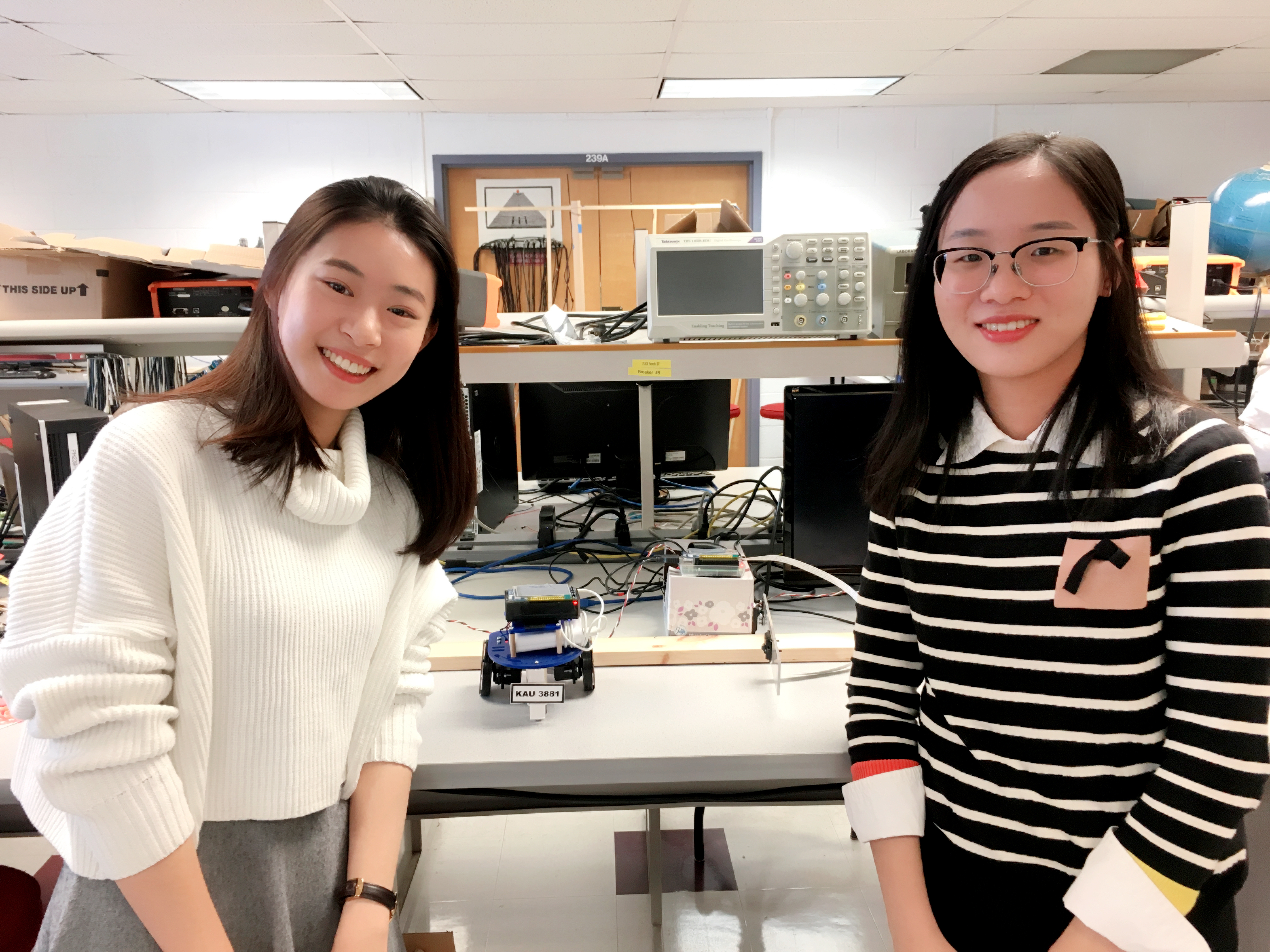
Project group picture
Xinyue Zhou (Lois)
xz677@cornell.edu
Designed the overall software architecture. Tested and debugged of all.
Jingyi Hu (Ginny)
jh2677@cornell.edu
Designed the overall hardware architecture. Tested and debugged of all.
Parts List
| Components | Cost | Number | Total Cost |
|---|---|---|---|
| Raspberry Pi Model 3 B+ | $35 | 2 | $70 |
| Camera | $25 | 1 | $25 |
| IR sensor | $5.83 | 2 | $11.66 |
| Servos, Resistors and Wires | Provided in lab | ||
| Final Cost | $106.66 |
References
IR Sensor DatasheetStandard Servo Datasheet
Laser Cutting Instruction
Continuous Rotation Servo Datasheet
PiCamera Document
OpenCV2 Document
OpenCV3 Document
Text Skew Correction
OCR Tesseract
Code Appendix
1 2 3 4 5 6 7 8 9 10 11 12 13 14 15 16 17 18 19 20 21 22 23 24 25 26 27 28 29 30 31 32 33 34 35 36 37 38 39 40 41 42 43 44 45 46 47 48 49 50 51 52 53 54 55 56 57 58 59 60 61 62 63 64 65 66 67 68 69 70 71 72 73 74 75 76 77 78 79 80 81 82 83 84 85 86 87 88 89 90 91 92 93 94 95 96 97 98 99 100 101 102 103 104 105 106 107 108 109 110 111 112 113 114 115 116 117 118 119 120 121 122 123 124 125 126 127 128 129 130 131 132 133 134 135 136 137 138 139 140 141 142 143 144 145 146 147 148 149 150 151 152 153 154 155 156 157 158 159 160 161 162 163 164 165 166 167 168 169 170 171 172 173 174 175 176 177 178 179 180 181 182 183 184 185 186 187 188 189 190 191 192 193 194 195 196 197 198 199 200 201 202 203 204 205 206 207 208 209 210 211 212 213 214 215 216 217 218 219 220 221 222 223 224 225 226 227 228 229 230 231 232 233 234 235 236 237 238 239 240 241 242 243 244 245 246 247 248 249 250 251 252 253 254 255 256 257 258 259 260 261 262 263 264 265 266 267 268 269 270 271 272 273 274 275 276 277 278 279 280 281 282 283 284 285 286 287 288 289 290 291 292 293 294 295 296 297 298 299 300 301 302 303 304 305 306 307 308 309 310 311 312 313 314 315 316 317 318 319 320 321 322 323 324 325 326 327 328 329 330 331 332 333 334 335 336 337 338 339 340 341 342 343 344 345 346 347 348 349 350 351 352 353 354 355 356 357 358 359 360 361 362 363 364 365 366 367 368 369 370 371 372 373 374 375 376 377 378 379 380 381 382 383 384 385 386 387 388 389 390 391 392 | # # main code # image processing, recognition, whole logic, pygame display # ###Libraries## import RPi.GPIO as GPIO import time from picamera import PiCamera from time import sleep from PIL import Image # Importing the Opencv Library import cv2 import numpy as np import argparse #pygame import pygame from pygame.locals import * import os import subprocess ####sevol control#### import sys import pigpio #run cmd import subprocess ###################################################################################### #initialize # Set for broadcom numbering so that GPIO# can be used as reference GPIO.setmode(GPIO.BCM) GPIO.setup(17, GPIO.IN, pull_up_down=GPIO.PUD_UP) GPIO.setup(27, GPIO.IN, pull_up_down=GPIO.PUD_UP) ##IR sersor signal input GPIO.setup(19, GPIO.IN) GPIO.setup(26, GPIO.IN) camera = PiCamera() os.putenv('SDL_VIDEODRIVER', 'fbcon') # Display on piTFT os.putenv('SDL_FBDEV', '/dev/fb1') os.putenv('SDL_MOUSEDRV', 'TSLIB') # Track mouse clicks on piTFT os.putenv('SDL_MOUSEDEV', '/dev/input/touchscreen') pygame.init()#pygame initialization pygame.mouse.set_visible(False) #RGB color WHITE = 255, 255, 255 BLACK = 0,0,0 RED = 255,0,0 GREEN = 0,255,0 start_time=time.time()#tiem when program start screen = pygame.display.set_mode((320, 240)) my_font = pygame.font.Font(None,25) ######################################################################################## #functions def imageCap(): camera.resolution = (2592, 1944) #camera.rotation=180 camera.framerate = 15 camera.start_preview() camera.brightness = 65#default50 camera.rotation=0 time.sleep(2) camera.capture('image.jpg') camera.stop_preview() def imageProcess(): ##number plate localization and background delete # Importing NumPy,which is the fundamental package for scientific computing with Python global start_time start_time=time.time() # Reading Image img_0 = cv2.imread("image.jpg") img = img_0[900:1700,500:1700] #can be restrict to smaller region cv2.imwrite('display0.jpg',img) # RGB to Gray scale conversion img_gray = cv2.cvtColor(img,cv2.COLOR_BGR2GRAY) # Noise removal with iterative bilateral filter(removes noise while preserving edges) noise_removal = cv2.bilateralFilter(img_gray,9,75,75) # Histogram equalisation for better results equal_histogram = cv2.equalizeHist(noise_removal) # Morphological opening with a rectangular structure element kernel = cv2.getStructuringElement(cv2.MORPH_RECT,(5,5)) morph_image = cv2.morphologyEx(equal_histogram,cv2.MORPH_OPEN,kernel,iterations=15) # Image subtraction(Subtracting the Morphed image from the histogram equalised Image) sub_morp_image = cv2.subtract(equal_histogram,morph_image) # Thresholding the image ret,thresh_image = cv2.threshold(sub_morp_image,0,255,cv2.THRESH_OTSU) # Applying Canny Edge detection canny_image = cv2.Canny(thresh_image,250,255) canny_image = cv2.convertScaleAbs(canny_image) # dilation to strengthen the edges kernel = np.ones((3,3), np.uint8) # Creating the kernel for dilation dilated_image = cv2.dilate(canny_image,kernel,iterations=1) # Finding Contours in the image based on edges contours, hierarchy = cv2.findContours(dilated_image, cv2.RETR_TREE, cv2.CHAIN_APPROX_SIMPLE) contours= sorted(contours, key = cv2.contourArea, reverse = True)[:10] # Sort the contours based on area ,so that the number plate will be in top 10 contours screenCnt = None # loop over our contours loop = 1 for c in contours: print ("loop #: " + str(loop)) loop = loop+1 # approximate the contour peri = cv2.arcLength(c, True) approx = cv2.approxPolyDP(c, 0.06 * peri, True) # Approximating with 6% error print ("approx: " + str(len(approx))) # if our approximated contour has four points, then # we can assume that we have found our screen if len(approx) == 4: # Select the contour with 4 corners screenCnt = approx top_left = approx[0][0] #[x y] top_right = approx[1][0] bottom_left = approx[2][0] bottom_right = approx[3][0] top_idx = min(top_left[1], top_right[1]) bottom_idx = max(bottom_left[1], bottom_right[1]) left_idx=min(min(top_left[0], top_right[0]),min(bottom_left[0], bottom_right[0])) right_idx=max(max(top_left[0], top_right[0]),max(bottom_left[0], bottom_right[0])) print ("Yay, find one") break ## Masking the part other than the number plate mask = np.zeros(img_gray.shape,np.uint8) new_image = cv2.drawContours(mask,[screenCnt],0,255,-1,) new_image = cv2.bitwise_and(img,img,mask=mask) # Histogram equal for enhancing the number plate for further processing y,cr,cb = cv2.split(cv2.cvtColor(new_image,cv2.COLOR_BGR2YCR_CB)) # Converting the image to YCrCb model and splitting the 3 channels y = cv2.equalizeHist(y) # Applying histogram equalisation final_image = cv2.cvtColor(cv2.merge([y,cr,cb]),cv2.COLOR_YCR_CB2BGR) # Merging the 3 channels #cv2.namedWindow("12_Extract",cv2.WINDOW_NORMAL) #print(new_image.shape) final_new_image = new_image[top_idx:bottom_idx,left_idx:right_idx ] print(final_new_image.shape) #cv2.imshow("12_Extract", final_new_image) cv2.imwrite('result1.jpg',new_image) cv2.imwrite('result2.jpg',final_new_image) im = final_new_image im[np.where((im <[20,20,20]).all(axis = 2))] = [255,255,255] gray = cv2.cvtColor(im, cv2.COLOR_BGR2GRAY) ret, binary = cv2.threshold(gray, 0, 255, cv2.THRESH_BINARY_INV | cv2.THRESH_OTSU) kernel = cv2.getStructuringElement(cv2.MORPH_RECT, (1, 6)) binl = cv2.morphologyEx(binary, cv2.MORPH_OPEN, kernel) kernel = cv2.getStructuringElement(cv2.MORPH_RECT, (5, 1)) open_out = cv2.morphologyEx(binl, cv2.MORPH_OPEN, kernel) cv2.bitwise_not(open_out, open_out) #cv2.namedWindow("Transfered",cv2.WINDOW_NORMAL) #cv2.imshow("Transfered", open_out) cv2.imwrite('output1.jpg', open_out) def correctSkew(): ###correct Skew # load the image from disk image = cv2.imread("output1.jpg") # convert the image to grayscale and flip the foreground # and background to ensure foreground is now "white" and # the background is "black" gray = cv2.cvtColor(image, cv2.COLOR_BGR2GRAY) gray = cv2.bitwise_not(gray) # threshold the image, setting all foreground pixels to # 255 and all background pixels to 0 thresh = cv2.threshold(gray, 0, 255, cv2.THRESH_BINARY | cv2.THRESH_OTSU)[1] # grab the (x, y) coordinates of all pixel values that # are greater than zero, then use these coordinates to # compute a rotated bounding box that contains all # coordinates coords = np.column_stack(np.where(thresh > 0)) angle = cv2.minAreaRect(coords)[-1] # the `cv2.minAreaRect` function returns values in the # range [-90, 0); as the rectangle rotates clockwise the # returned angle trends to 0 -- in this special case we # need to add 90 degrees to the angle if angle < -45: angle = -(90 + angle) # otherwise, just take the inverse of the angle to make # it positive else: angle = -angle # rotate the image to deskew it (h, w) = image.shape[:2] center = (w // 2, h // 2) M = cv2.getRotationMatrix2D(center, angle, 1.0) rotated = cv2.warpAffine(image, M, (w, h), flags=cv2.INTER_CUBIC, borderMode=cv2.BORDER_REPLICATE) cv2.imwrite("output2.jpg", rotated) def image_resize(filename, mwidth, mheight): image = Image.open(filename) w,h = image.size if w<=mwidth and h<=mheight: print(filename,'is OK.') return if (1.0*w/mwidth) > (1.0*h/mheight): scale = 1.0*w/mwidth new_im = image.resize((int(w/scale), int(h/scale)), Image.ANTIALIAS) else: scale = 1.0*h/mheight new_im = image.resize((int(w/scale),int(h/scale)), Image.ANTIALIAS) new_im.save('display.jpg') new_im.close() def servoControl(): pi_hw = pigpio.pi() # connect to pi gpio daemon up_t=0.00225 #pulse duration T=up_t+0.02 #1 period time f=1/T #46.51Hz dc=(up_t/T)*1000000 pi_hw.hardware_PWM(13,f,dc) time.sleep(3) pi_hw.hardware_PWM(13,0,0) time_servo=time.time() flag=1 count=0 try: while flag: time.sleep(0.2) screen.fill(BLACK) # Erase the Work space time.sleep(0.2) # Without sleep, no screen output! display="Number plate is: " + text text_surface = my_font.render(display, True, WHITE)#display Left servo History coloum rect = text_surface.get_rect(center=(160,30)) screen.blit(text_surface, rect) #dispaly the captured image on piTFT image_resize('display0.jpg', 160, 160) imDisplay = pygame.image.load("display.jpg") #draw rectangle imRec = imDisplay.get_rect() #initil position of two balls imRec.right=240 imRec.top=60 screen.blit(imDisplay, imRec) # Combine surface with workspace surface if((text=='KAU 3881') or (text=='FBR 1449')): #test whether match with the one in database display="Allow Pass" text_surface = my_font.render(display, True, WHITE)#display Left servo History coloum rect = text_surface.get_rect(center=(160,210)) screen.blit(text_surface, rect) pygame.display.flip()#dispaly on actual screen if(count==0): t=0.00125 T=t+0.02 frequency=1/T dc=(t/T)*1000000 #p.ChangeDutyCycle(dc) pi_hw.hardware_PWM(13,f,dc) time.sleep(3) pi_hw.hardware_PWM(13,0,0) count=1 if ( not GPIO.input(26) ): print (" ") print "IR sensor2!" t=0.00225 T=t+0.02 frequency=1/T dc=(t/T)*1000000 pi_hw.hardware_PWM(13,f,dc) time.sleep(3) pi_hw.hardware_PWM(13,0,0) flag=False elif ( not GPIO.input(27) ): print (" ") print "Button 27 has been pressed" flag=False else: display="Not Allow" text_surface = my_font.render(display, True, WHITE)#display Left servo History coloum rect = text_surface.get_rect(center=(160,210)) screen.blit(text_surface, rect) pygame.display.flip()#dispaly on actual screen if((time.time()-time_servo)>5): flag=False screen.fill(BLACK) # Erase the Work space pygame.display.flip()#dispaly on actual screen except KeyboardInterrupt: pass pi_hw.stop() #close pi gpio DMA resources ####################################################################################### #main loop flag=True while flag: screen.fill(BLACK) # Erase the Work space time.sleep(0.2) # Without sleep, no screen output! display="Welcome to 677 Parking" text_surface = my_font.render(display, True, WHITE)#display Left servo History coloum rect = text_surface.get_rect(center=(160,60)) screen.blit(text_surface, rect) pygame.display.flip()#dispaly on actual screen if ( not GPIO.input(19) ):#when button pressed pin connected to ground, GPIO.input(17)=0; print (" ") print "IR sensor1!" imageCap() imageProcess() #start_time here correctSkew() ##OCR recognize #use command line ro do ocr cmd="tesseract output2.jpg file -l eng -psm 7" #english single line print subprocess.check_output(cmd, shell=True) #monitor the image processing time #print ("time for image processing and recognition is:" + str(time.time()-start_time)) f = open("file.txt","r") text = f.readline() text=text.replace("\n", "") f.close() servoControl() #lift up servo if number plate is mach #display not allow if number plate not match if ( not GPIO.input(27) ): print (" ") print "Button 27 has been pressed system out" flag=False GPIO.cleanup() |
1 2 3 4 5 6 7 8 9 10 11 12 13 14 15 16 17 18 19 20 21 22 23 24 25 26 27 28 29 30 31 32 33 34 35 36 37 38 39 40 41 42 43 44 45 46 47 48 49 50 51 52 53 54 55 56 57 58 59 60 61 62 63 64 65 66 67 68 69 70 71 72 73 74 75 76 77 | #carControl # import time import os import RPi.GPIO as GPIO import subprocess import pigpio import sys GPIO.setmode(GPIO.BCM)#set mode to BCM GPIO.setup(17, GPIO.IN, pull_up_down=GPIO.PUD_UP) GPIO.setup(27, GPIO.IN, pull_up_down=GPIO.PUD_UP) #T=0.0015+0.02 #f=1/T #dc=0.0015/(0.0015+0.02)*100=6.9767---calibriation signal def control_servo(ser_num, direction):#Two parameter dicide state of servos if ser_num=="Left": if direction=="clockwise": print " Left servo, clockwise" dc=6.9767*10000 pi_hw.hardware_PWM(13,46.5,dc) elif direction=="stop": print " Left servo, stop" pi_hw.hardware_PWM(13,0,0)# complete stop when duty cycle=0, no output elif direction=="counter-clockwise": print " Left servo, counter-clockwise" dc=6.9767*10000#duty cycle in % pi_hw.hardware_PWM(13,46.5,dc) elif ser_num=="Right":# Do the same as for Left servo if direction=="clockwise": print " Right servo, clockwise" dc=6.9767*10000#duty cycle in % pi_hw.hardware_PWM(12,46.5,dc) elif direction=="stop": print " Right servo, stop" pi_hw.hardware_PWM(12,0,0) elif direction=="counter-clockwise": print " Right servo, counter-clockwise" dc=6.9767*10000 pi_hw.hardware_PWM(12,46.5,dc) pi_hw = pigpio.pi() # connect to pi gpio daemon resume=0 # stop/ start flag=1# flag to end while loop while flag: time.sleep(0.2) # Without sleep, no screen output! if ( not GPIO.input(17) ):#when button pressed pin connected to ground, GPIO.input(17)=0; if(resume==0): control_servo("Left", "clockwise") control_servo("Right", "counter-clockwise") resume=1 elif(resume==1): control_servo("Left", "stop") control_servo("Right", "stop") resume=0 if ( not GPIO.input(27) ): flag=0 pi_hw.stop() #close pi gpio DMA resources GPIO.cleanup()#aviod conflt when other program running |