ECE5725 Project Multipurpose Operator
By Chenye Li and Zixin Chen
Demonstration Video
Project Objective
The objective of this project is to create a device that can perform operations on a plane. Nowadays, we can get bonuses from many mobile phone software by login and complete some particular tasks every day (for example we can earn credit points in some software by logging in, touch some special buttons or watch some videos). However, the process to get those bonuses can be boring and sometimes complicate. This brings to the first function of the device which is to perform a certain touch and swipe operation pattern on a mobile phone that helps the user to complete the tasks stated above. Adopting the idea from the 2D-plotter, the second function of the device is to plot a image on a paper with a pen mounted on the device.
Introduction
There were three phases of this project. Phase one was to design mechanical parts. In this phase, pre-manufactured CNC (computer numerical control) parts including pulleys, cylinder liner rails, and slide bushings were purchased from Amazon.com. After measuring the exact dimensions of the purchasing parts, all the other moving parts were designed and 3D printed. The frame of the device was built with wood sticks with help from Dr. Joe Skovira.
Phase two was to complete the hardware design and connect all the electronic parts together. In this phase, stepper motors, stepper motor drivers, distance infrared sensors, and a control circuit was tested and mounted on the frame of the device.
Phase three was software design. In this phase, multiple programs were developed to accomplished different objectives. The final and most complicated task that had been achieved was plotting an arbitrary input image.
Design
Phase I. Mechanical Part Design
First, we need to make sure that our pen can move freely in a 2D plane and move up and down in the third dimension. So we used two rails and slides for X direction movement and another two rails and slides for Y direction movement. We used 3D printer to print two plastic components which can hold another two rails with slide bushings in Y direction. We also printed a pen holder which could be mounted on the two slide bushings. The following image shows the original look of our design.
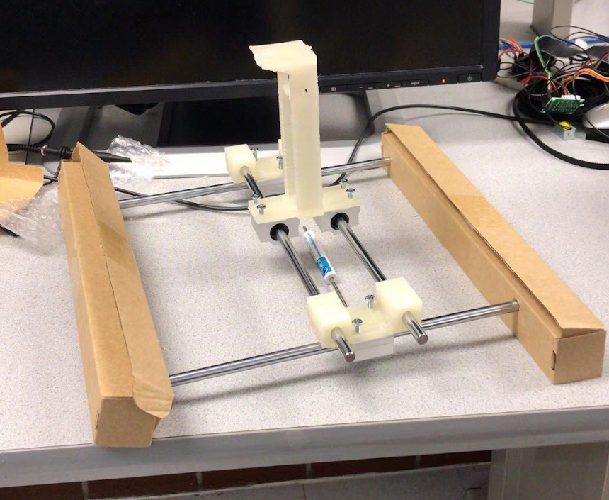
Figure 1 Original Look of the Design
To move those slide bushings, we need to use stepper motors. The best way to achieve this was to suspend those rails and stick the belts and motors under them. So, we cut down four wooden blocks to make a square as a frame. Two of the blocks had two holes to fix the rail. On the pen holder, we had a solenoid with a thin cable to control the holding plane up and down. Finally, we stick one motors on the side of a wooden block, and the other on the plastic components on the Y direction slide bushing. The following image shows the final version of our design.
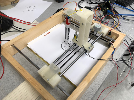
Figure 2 Final Look of theDesign
Phase II. Hardware design
We used drivers to control our step motor. Each driver had five output pins. The fifth pin always had high voltage while the other four would change their output voltage according to the driver inputs. With high inputs (“1”), the output voltage was low (“0”); with low inputs (“0”), the output voltage was high (“1”). To control it, we allocated four GPIO output for each step motor. We used GPIO output to generate the signal sequence as below to activate the stepper motor clockwise. To go counterclockwise, we used the signal sequence in opposite direction.
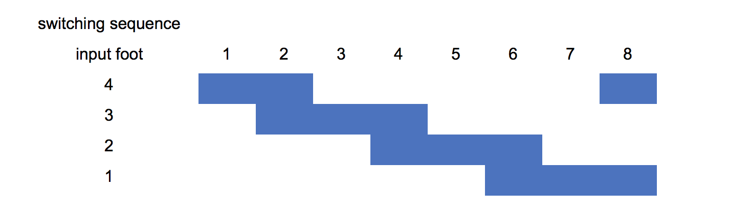
Figure 3 Stepper Motor Signal Sequence Sheet
We also used the same driver to control our solenoid. We connected our solenoid between foot 1 and foot 5. When there is no input signal, the solenoid had no current go across and it would release itself. When there is a input signal, the solenoid would be triggered and plug down the cable.
In case of moving outside the appropriate area and destroying itself, we used two infrared sensors to calibrate our slides. When it senses something in front of it, the output will be “0”. So we allocated two GPIO input for calibration. Once the GPIO get “0” input, the stepper motor would be stopped.
Phase III. Software design
As mentioned before, we needed to generate a signal sequence to activate our stepper motor. We allocated GPIO 13,19,22,6 for stepper motor 1 and GPIO 18,23,24,25 for stepper motor two. At each transition, we could adjust the sleep time to control the velocity of stepper motor. In this way, we could control the distance of each movement of our pen. We wrote four basic atom function: motor1clockwise, motor1counterclockwise, motor2clockwise and motor2counterclockwise. Each function needs two parameters: running time and velocity. They used time.sleep(velocity) to control the rotating speed of stepper motor; and they used thread.timer() to exit the function when they reached the running time.
Then we created a function called movement. The function needs the temporary position and future position which should be saved in a list or function. After that, it would calculate (future position - temporary position)/velocity as running time (both X and Y directions have their position and running time). When the running time was positive, it would call clockwise functions and when the running time was negative, it would call counterclockwise funcitons. The movement function also had two parameters called zposition now and zposition after. These two parameters would judge the position of our pen before and after the movement.
Before drawing, we also need to calibrate our coordinate system. According to experiments, we found that the moving distance linearly depend on running time. So we wrote a script to move the slides from one side to the other and calculated the total time. Then, we used the largest time to rescale all the x position and y position.
Providing those functions and coordinates system, we need to accomplish two kinds of tasks: drawing continuous lines and discrete points. For continuous lines, our program firstly trigger the solenoid by GPIO 17. Then we use a function to generate a sequence of points on the trail. All those points should near each other. For example, for straight lines, the function was y=kx and the points may be [(0,0),(1,2),(2,4)....]; for a circle, the function was y=sin(wt) x=cos(wt) and the points can be generated through a loop. Then we send those points into the movement function with zposition now=1 and zposition after=1. In this way, we could draw any line we like. For discrete points, we needed to have a points list. We used number “4” as an example. We took a picture of a handwritten “4” and made it into a binary image. Then we sent all the coordinates who have non-zero values to our program. The program will first rescalse them by xlist * totaltime / Max(xlist,ylist); ylist * totaltime / Max(xlist,ylist). Then they would be sent to function movement in a loop. Xlist[i] and ylist[i] would be position now and xlist[i+1] and ylist[i+1] would be position after. Zposition now would be 1 and zposition after would be 0. In this way, we could draw each point at exact positions.
Testing
Phase I. Mechanical Part Testing
After we assembled our machine, we tested our rails, slides, wooden blocks and 3D printing components. The most difficult task we were faced was to fix the stepper motor on the wooden block and plastic component. We had to make sure that the belt was horizontally attached to the slides. To achieve that, we printed two more holding components to fix another two gears. Finally our pen holder could move freely in X-Y plane.
Phase II. Hardware Testing
The most important part in our design was solenoid. It was the key component to control the pen up and down. However, it need a large current to trigger itself, which Raspberry Pi couldn’t afford. First, we tried to use amplifying circuits (with transistors and Op-Amps) to amplify the signals from Pi. But they still failed to provide enough current. Then we decided to use the drivers which we bought together with the stepper motor. It magically worked well. Then we had to find a way to connect our solenoid with the pen holder. After several attempts, we chose to use a soft cable which was tight but not solid.
In fact, the most tough part of our design was dealing with practical issues. We clearly realized that we couldn’t foresee all the troubles and risks while we were designing. But we must overcome them after they jumped out. We drew and cancelled the CAD figures again and again in order to find the best way to assemble our machine. We spent hours polishing our 3D printing components because the holes on them were not accurate enough. We also spent days to find the best position for our motors, solenoid, infrared sensors, with punching holes, cutting components and sticking. Finally we succeed to let our machine work smoothly and accurately.
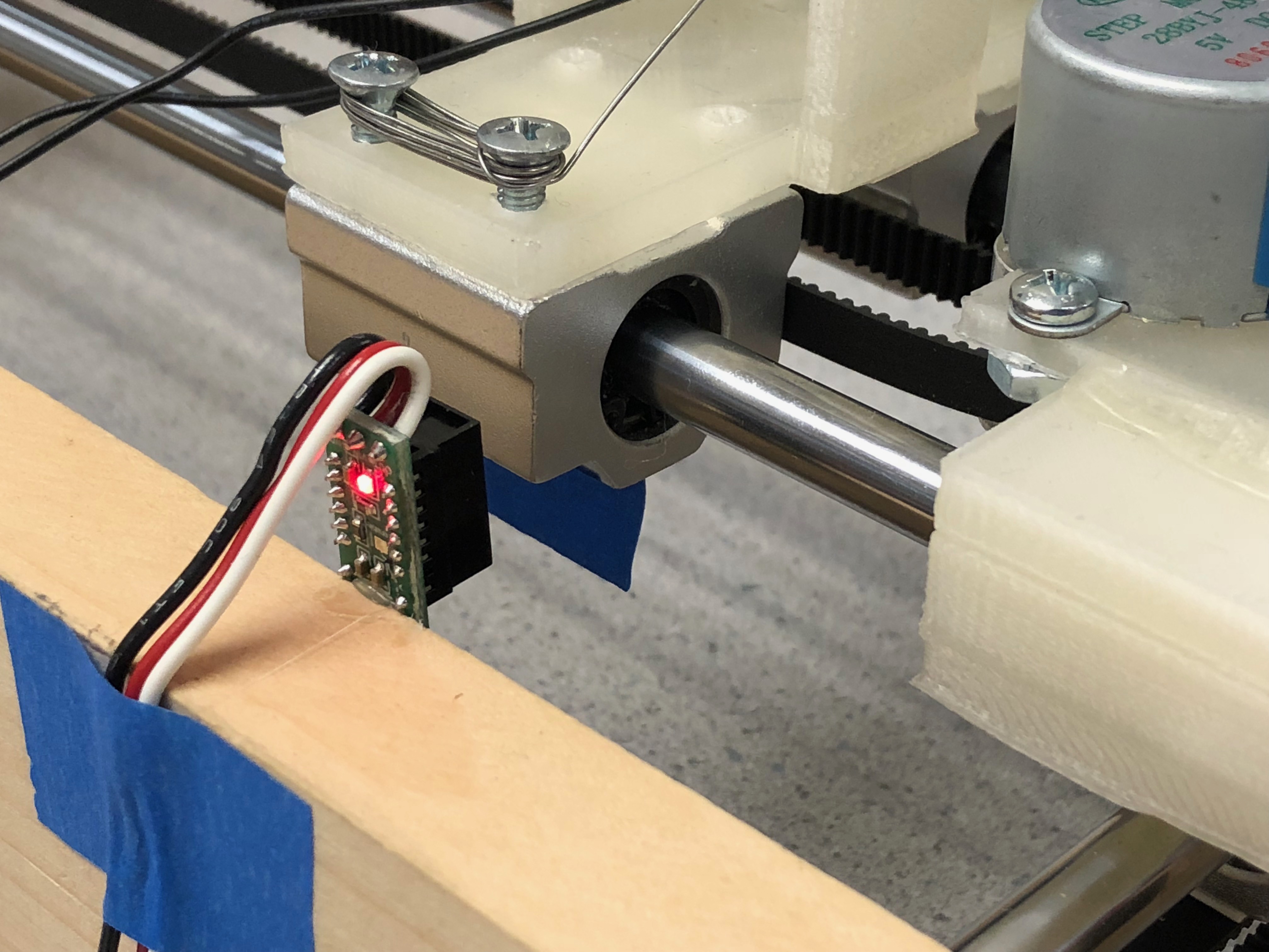
Figure 4 Infrared Sensor
Phase III. Software Testing
Calibration test: We had two calibration program, one was user calibration and the other was automatic calibration.
For the user calibration, the user need to choose exact stepper motor and direction with specific running time. Then the pen holder would move according to the input. This program could let the user move the pen holder to some exact position they want.
For the automatic calibration, the program would calibrate the pen holder to (0,0) point in our coordinate system. Every time before drawing program, automatic calibration should be ran.
Drawing test:
Drawing test: Continuous line: we tested our continuous line program by drawing a smiling face. The program should draw one large circle, two small circle, one triangular and one part circle (by pushing up the pen at some position when drawing a circle). The following image shows the result of this program.
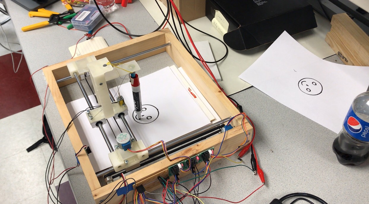
Figure 5 Drawing a Smiley Face
Discrete points: we tested our discrete points program by drawing character “4”. We use preprocessor program to translate our image into a (x,y) list. Then we sent the list to our drawing program. It successfully drew a character “4” with discrete points.
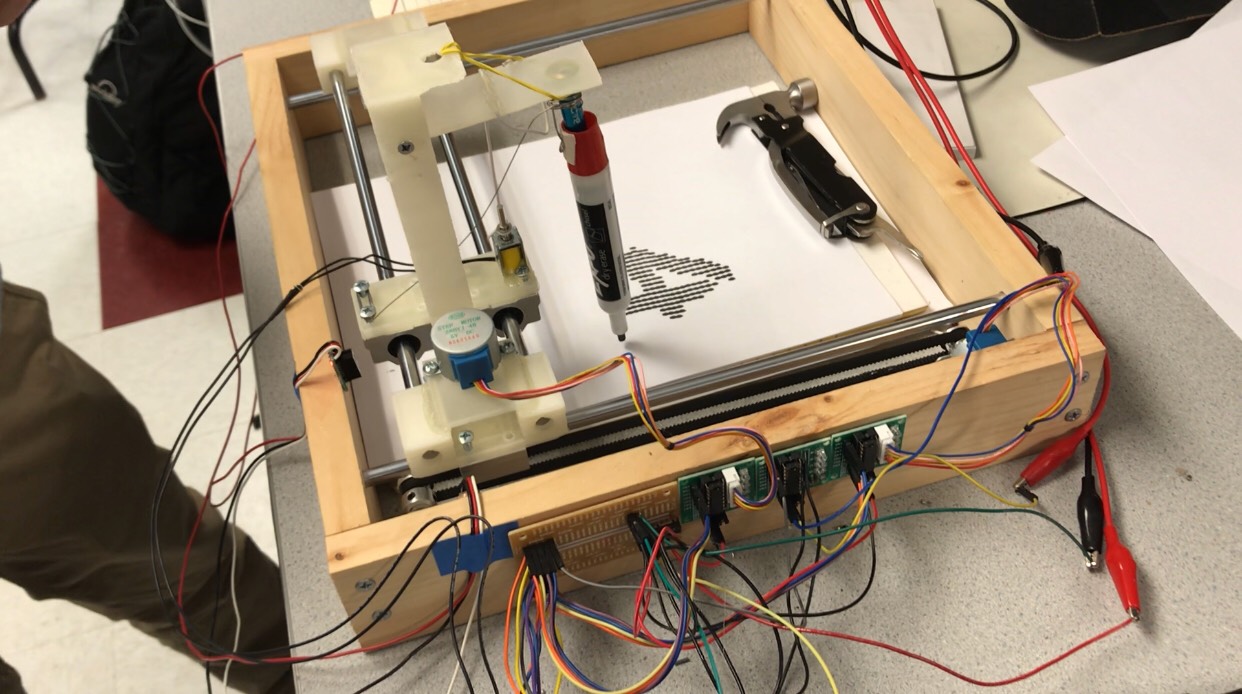
Figure 6 Drawing a Number "4"
Result
As described in the previous sections, the main functions of the device that we proposed were successfully achieved. The only unexpected situation was that the solenoid we had chosen to use would draw a massive amount of current when activated. Because of the high current, the driver was melted down and fried during out testing. Then, all the GPIO ports on the Raspberry Pi 3 dead for the same reason. To prevent from causing any further damage, we set a current output limit during our final demo. Since the current was not high enough, the solenoid could only hold the stylus with very limited strength. In other words, the touch force of the stylus was not powerful enough to be recognized by the touchscreen on a smartphone. As a result, only the plotting function was presented. However, the swiping and touching commands were demonstrated functional with the continuous line smiley face and the dotted-four plottings respectively.
. 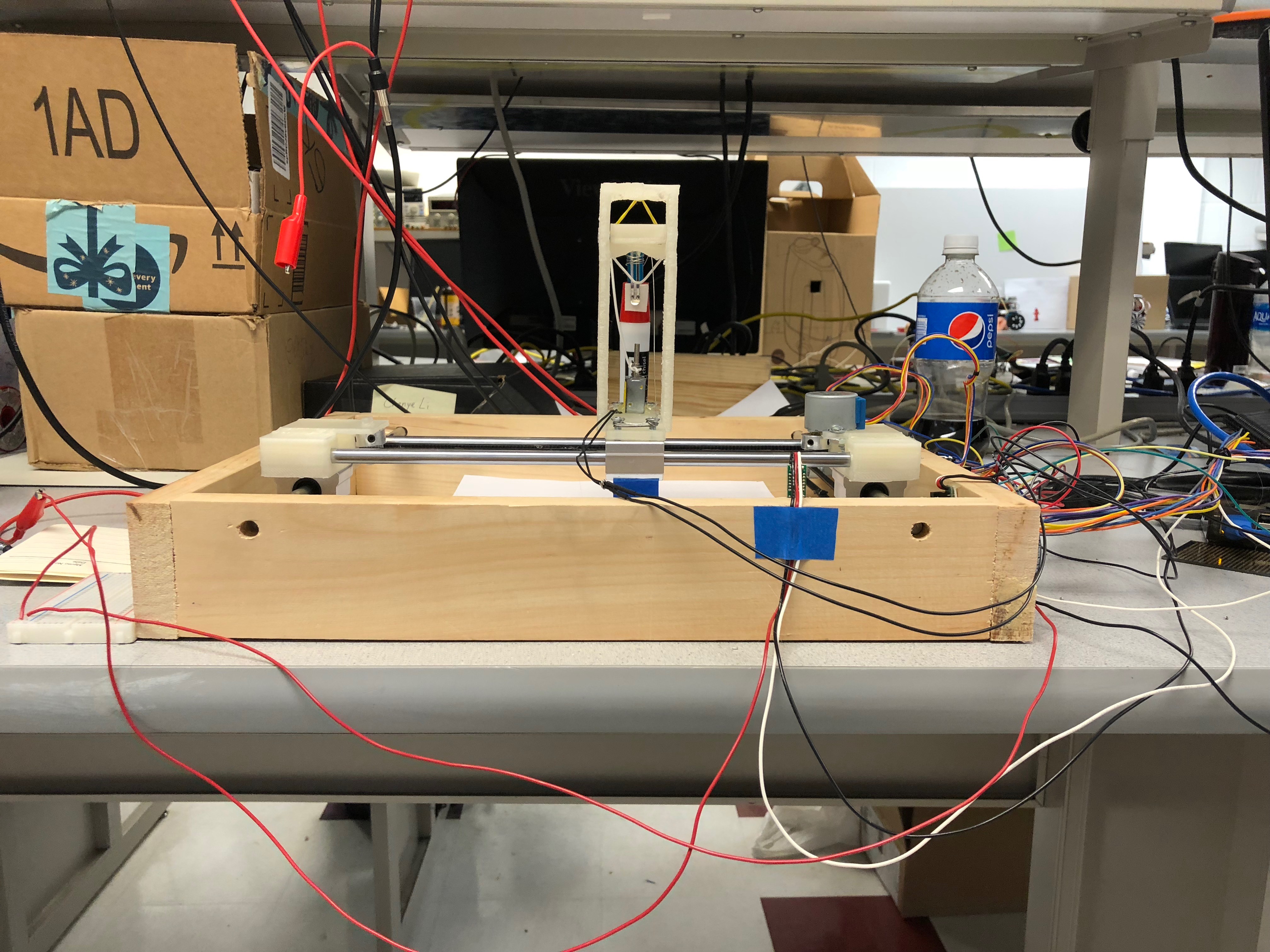
Figure 7 Device Front View
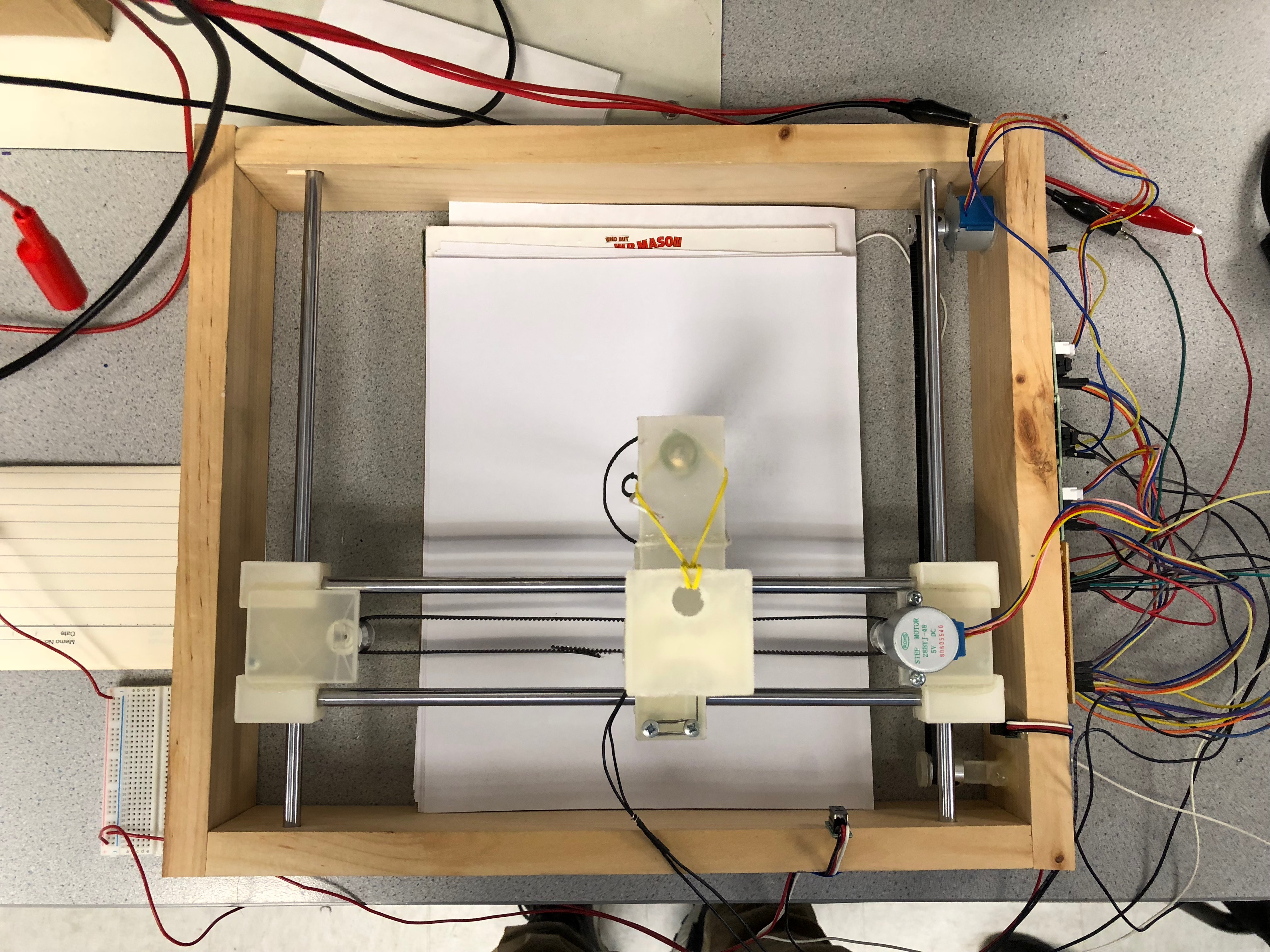
Figure 8 Device Top View
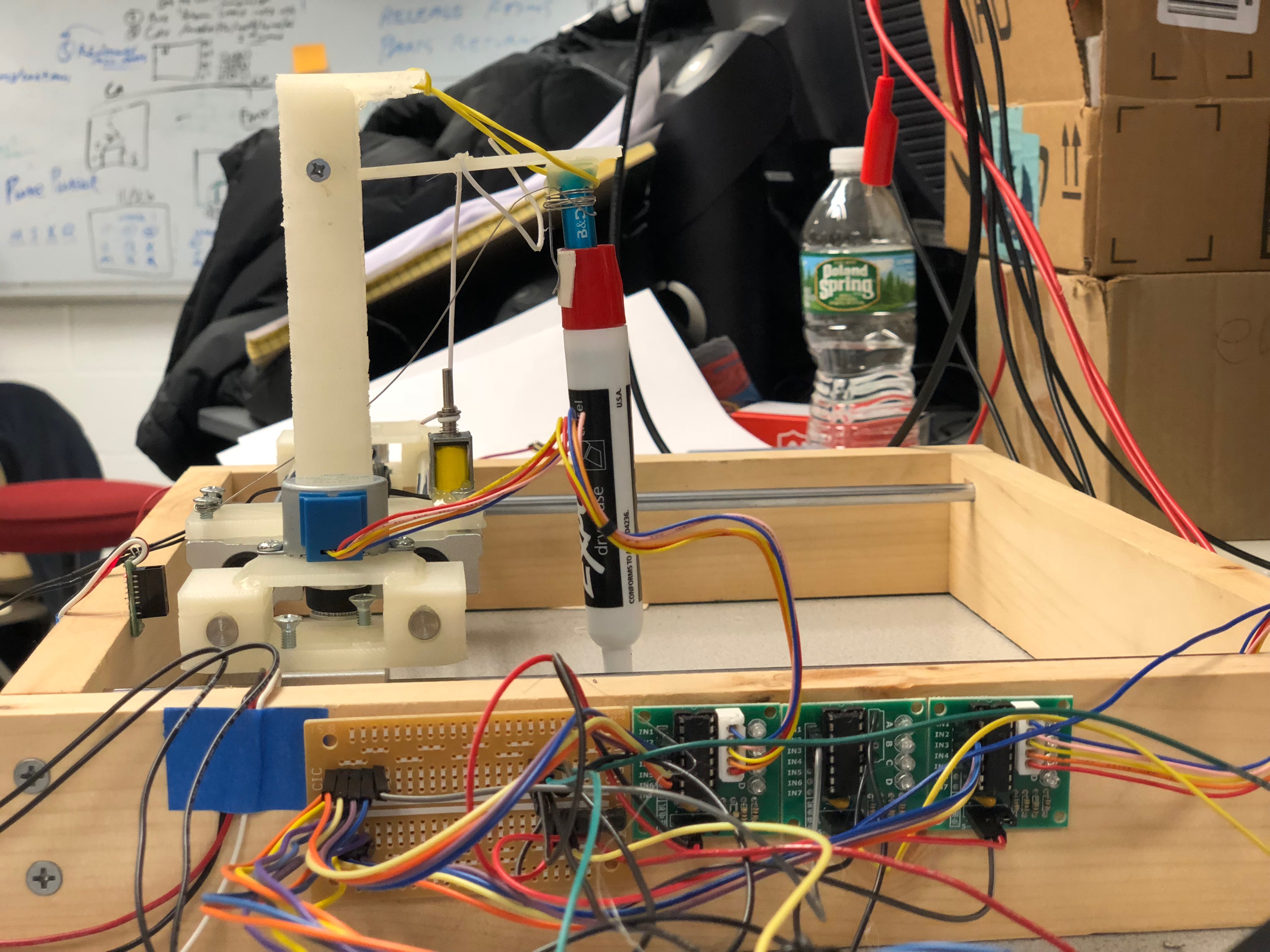
Figure 9 Device Side View
Conclusion
In summary, the team successfully realized the function of controlling the movement of a pen on a plain. To be more specific, we first assembled all the parts (including the CNC parts, 3D printing parts, and wood parts) together and made it work without any electronic control. Second, all the sensors, motors, drivers, and design circuits were tested separately with separate control programs (functions). Third, the electronic part and the mechanical part were put together. Finally, different versions of control software were developed with those predefined functions. During our testing, we had explored that the real world situations were always complicated than that defined in theories. For example, we tried to use one transistor (MOSFET or BJT) as a switch between a low power circuit and a high power circuit. In theory, when applying a logic high voltage to the gate (or base) of the transistor, a current should be allowed to flow through the other two ports. In reality, due to the gain in both input and output sides of the ports, it was hard to make the transistor to work at a proper point on the characteristic curve of the transistor. It becomes even more complicated when we added more transistors attempting to solve the problem. Finally, we turned to use a driver chip to solve the problem.
Future Work
The future works of this project are as follows.
1. Refine the circuit design to reduce the number of power supplies
Currently, the device is a lab version prototype that works with at least 3 different power supplies include the pi power supply. The purpose of this step is to reduce the number of these power supplies to make it more compact and product-like.
2. Replace solenoid driver
As mentioned in the previous parts, the solenoid on our current version device is not powerful enough as a mobile phone operator. One simple solution is to replace the solenoid driver with another one that holds a high current.
3. Develop a more user-friendly software
Currently, a user needs to run different programs to achieve tasks such as calibration, taking input, and plotting. After doing this step, a user should be able to achieve different task combinations with only one click.
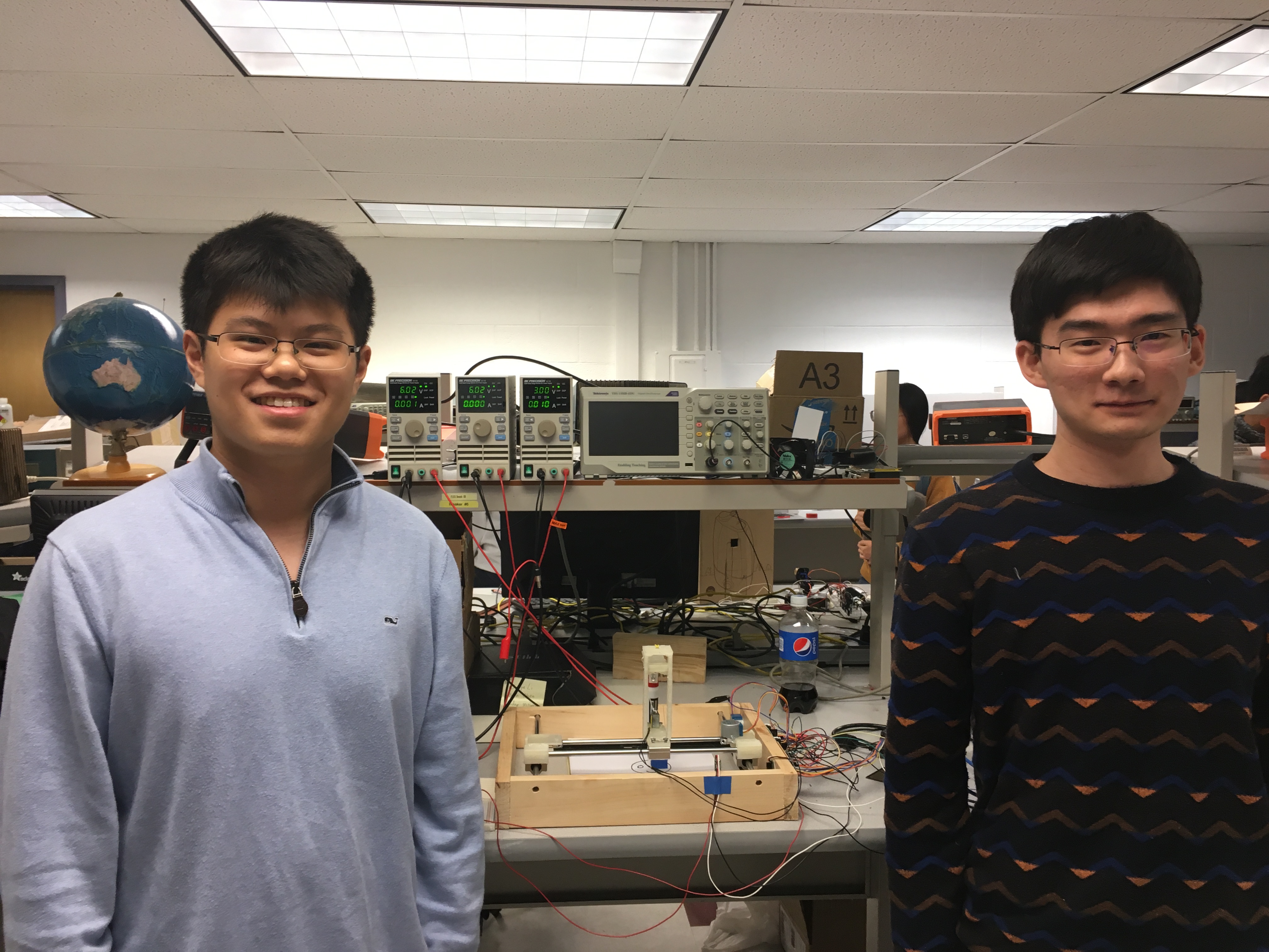
Team
Group Photo

Chenye Li
cl2553@cornell.edu
Designed the overall mechanical architecture; Designed the overall hardware architecture; Developed the basic control algorithm; Assembled the parts

Zixin Chen
zc422@cornell.edu
Drew CAD figures; Wrote solenoid and stepper motor testing programs; Wrote Automatic calibration programs; Wrote Continuous and Discrete drawing programs; Assembled the parts; Designed the mechanical architesture
Parts List
- Raspberry Pi 3 Model B: $35.00
- CNC Rails (4 pcs): $11.69
- Slide bushings (4 pcs): $10.36
- Stepper motors and drivers (5 pcs): $11.79
- Belt (5m) and pulleys: $10.21
- Infrared sensors Pololu GP2Y0D810Z0F: $7.49*2
- Stylus: $2.99
- Resistors and Wires - Provided in lab
- 3D printing parts - Provided by Maker Club
Total: $97.02
Reference
1. Multiprocessing — Process-based Parallelism
2. Francis Yu (fy57) and Xitang Zhao (xz522) Autonomous Object Tracking Turret, May 17th, 2018
3. Rpi GPIO
Code Appendix
# solenoid testing.py
# This python script define the basic function of controlling the solenoid
from multiprocessing import Process
import RPi.GPIO as GPIO
import time
import numpy as np
import os
import threading as th

GPIO.setmode(GPIO.BCM)
GPIO.setup(17,GPIO.OUT)
GPIO.output(17,0)

def magnet(t):
    GPIO.output(17,1)
    time.sleep(t)
    GPIO.output(17,0)

if __name__ == '__main__':
    m = Process(target=magnet, args=(1.,))
    m.start()
    m.join()

GPIO.cleanup()
# stepper motor testing.py
# This python script define the basic function of controlling a stepper motor
import RPi.GPIO as GPIO
import time
import numpy as np
import os
import threading as th
import multiprocessing
from multiprocessing import pool
from multiprocessing import Process
import sys


GPIO.setmode(GPIO.BCM)
GPIO.setup(13,GPIO.OUT)
GPIO.setup(19,GPIO.OUT)
GPIO.setup(22,GPIO.OUT)
GPIO.setup(6,GPIO.OUT)
GPIO.output(13,0)
GPIO.output(19,0)
GPIO.output(22,0)
GPIO.output(6,0)

GPIO.setup(18,GPIO.OUT)
GPIO.setup(23,GPIO.OUT)
GPIO.setup(24,GPIO.OUT)
GPIO.setup(25,GPIO.OUT)
GPIO.output(18,0)
GPIO.output(23,0)
GPIO.output(24,0)
GPIO.output(25,0)
GPIO.setup(17, GPIO.IN, pull_up_down=GPIO.PUD_UP)


pin1=0
pin2=0
pin3=0
pin4=0

def GPIO17_callback(channel):
    global bbb
    global ccc
    bbb=False
    ccc=True

def exit1():
    global bbb
    bbb=False

def exit2():
    global ccc
    ccc=False


GPIO.add_event_detect(17,GPIO.FALLING, callback=GPIO17_callback, bouncetime=300)


bbb=True
ccc=True

def motor1clockfunc(speed,runningtime):
    th.Timer(runningtime,exit1).start()
    while bbb:
        GPIO.output(18,1)
        GPIO.output(25,0)
        time.sleep(speed)
        GPIO.output(23,1)
        time.sleep(speed)
        GPIO.output(18,0)
        time.sleep(speed)
        GPIO.output(24,1)
        time.sleep(speed)
        GPIO.output(23,0)
        time.sleep(speed)
        GPIO.output(25,1)
        time.sleep(speed)
        GPIO.output(24,0)
        time.sleep(speed)
        GPIO.output(18,1)
        time.sleep(speed)

    GPIO.output(18,0)
    GPIO.output(23,0)
    GPIO.output(24,0)
    GPIO.output(25,0)


def motor1counterclockfunc(speed,runningtime):
    th.Timer(runningtime,exit1).start()
    while bbb:
        GPIO.output(18,1)
        GPIO.output(23,0)
        time.sleep(speed)
        GPIO.output(25,1)
        time.sleep(speed)
        GPIO.output(18,0)
        time.sleep(speed)
        GPIO.output(24,1)
        time.sleep(speed)
        GPIO.output(25,0)
        time.sleep(speed)
        GPIO.output(23,1)
        time.sleep(speed)
        GPIO.output(24,0)
        time.sleep(speed)
        GPIO.output(18,1)
        time.sleep(speed)

    GPIO.output(18,0)
    GPIO.output(23,0)
    GPIO.output(24,0)
    GPIO.output(25,0)

def motor2clockfunc(speed,runningtime):
    th.Timer(runningtime,exit2).start()
    while ccc:
        GPIO.output(13,1)
        GPIO.output(6,0)
        time.sleep(speed)
        GPIO.output(19,1)
        time.sleep(speed)
        GPIO.output(13,0)
        time.sleep(speed)
        GPIO.output(22,1)
        time.sleep(speed)
        GPIO.output(19,0)
        time.sleep(speed)
        GPIO.output(6,1)
        time.sleep(speed)
        GPIO.output(22,0)
        time.sleep(speed)
        GPIO.output(13,1)
        time.sleep(speed)

    GPIO.output(13,0)
    GPIO.output(19,0)
    GPIO.output(22,0)
    GPIO.output(6,0)

def motor2counterclockfunc(speed,runningtime):
    th.Timer(runningtime,exit2).start()
    while ccc:
        GPIO.output(13,1)
        GPIO.output(19,0)
        time.sleep(speed)
        GPIO.output(6,1)
        time.sleep(speed)
        GPIO.output(13,0)
        time.sleep(speed)
        GPIO.output(22,1)
        time.sleep(speed)
        GPIO.output(6,0)
        time.sleep(speed)
        GPIO.output(19,1)
        time.sleep(speed)
        GPIO.output(22,0)
        time.sleep(speed)
        GPIO.output(13,1)
        time.sleep(speed)

    GPIO.output(13,0)
    GPIO.output(19,0)
    GPIO.output(22,0)
    GPIO.output(6,0)

if __name__ == '__main__':
    bbb=True
    ccc=True
    p1=Process(target=motor1clockfunc,args=(0.001,3.))
    p2=Process(target=motor2clockfunc,args=(0.001,3.))
    p1.start()
    p2.start()
    p1.join()
    p2.join()
    p1=Process(target=motor1counterclockfunc,args=(0.001,3.))
    p2=Process(target=motor2counterclockfunc,args=(0.001,3.))
    p1.start()
    p2.start()
    p1.join()
    p2.join()

"""
motor1clockfunc(0.001,5.)
bbb=True
motor1counterclockfunc(0.001,5.)
bbb=True

motor2clockfunc(0.001,5.)
ccc=True
motor2counterclockfunc(0.001,5.)
"""

GPIO.cleanup()
# User calibration.py
import RPi.GPIO as GPIO
import time
import numpy as np
import os
import threading as th
import multiprocessing
from multiprocessing import pool
from multiprocessing import Process
import sys


GPIO.setmode(GPIO.BCM)
GPIO.setup(13,GPIO.OUT)
GPIO.setup(19,GPIO.OUT)
GPIO.setup(22,GPIO.OUT)
GPIO.setup(6,GPIO.OUT)
GPIO.output(13,0)
GPIO.output(19,0)
GPIO.output(22,0)
GPIO.output(6,0)

GPIO.setup(18,GPIO.OUT)
GPIO.setup(23,GPIO.OUT)
GPIO.setup(24,GPIO.OUT)
GPIO.setup(25,GPIO.OUT)
GPIO.output(18,0)
GPIO.output(23,0)
GPIO.output(24,0)
GPIO.output(25,0)
GPIO.setup(17, GPIO.IN, pull_up_down=GPIO.PUD_UP)


pin1=0
pin2=0
pin3=0
pin4=0

def GPIO17_callback(channel):
    global bbb
    global ccc
    bbb=False
    ccc=True

def exit1():
    global bbb
    bbb=False

def exit2():
    global ccc
    ccc=False


GPIO.add_event_detect(17,GPIO.FALLING, callback=GPIO17_callback, bouncetime=300)


bbb=True
ccc=True

def motor1clockfunc(speed,runningtime):
    th.Timer(runningtime,exit1).start()
    while bbb:
        GPIO.output(18,1)
        GPIO.output(25,0)
        time.sleep(speed)
        GPIO.output(23,1)
        time.sleep(speed)
        GPIO.output(18,0)
        time.sleep(speed)
        GPIO.output(24,1)
        time.sleep(speed)
        GPIO.output(23,0)
        time.sleep(speed)
        GPIO.output(25,1)
        time.sleep(speed)
        GPIO.output(24,0)
        time.sleep(speed)
        GPIO.output(18,1)
        time.sleep(speed)

    GPIO.output(18,0)
    GPIO.output(23,0)
    GPIO.output(24,0)
    GPIO.output(25,0)


def motor1counterclockfunc(speed,runningtime):
    th.Timer(runningtime,exit1).start()
    while bbb:
        GPIO.output(18,1)
        GPIO.output(23,0)
        time.sleep(speed)
        GPIO.output(25,1)
        time.sleep(speed)
        GPIO.output(18,0)
        time.sleep(speed)
        GPIO.output(24,1)
        time.sleep(speed)
        GPIO.output(25,0)
        time.sleep(speed)
        GPIO.output(23,1)
        time.sleep(speed)
        GPIO.output(24,0)
        time.sleep(speed)
        GPIO.output(18,1)
        time.sleep(speed)

    GPIO.output(18,0)
    GPIO.output(23,0)
    GPIO.output(24,0)
    GPIO.output(25,0)


def motor2clockfunc(speed,runningtime):
    th.Timer(runningtime,exit2).start()
    while ccc:
        GPIO.output(13,1)
        GPIO.output(6,0)
        time.sleep(speed)
        GPIO.output(19,1)
        time.sleep(speed)
        GPIO.output(13,0)
        time.sleep(speed)
        GPIO.output(22,1)
        time.sleep(speed)
        GPIO.output(19,0)
        time.sleep(speed)
        GPIO.output(6,1)
        time.sleep(speed)
        GPIO.output(22,0)
        time.sleep(speed)
        GPIO.output(13,1)
        time.sleep(speed)

    GPIO.output(13,0)
    GPIO.output(19,0)
    GPIO.output(22,0)
    GPIO.output(6,0)


def motor2counterclockfunc(speed,runningtime):
    th.Timer(runningtime,exit2).start()
    while ccc:
        GPIO.output(13,1)
        GPIO.output(19,0)
        time.sleep(speed)
        GPIO.output(6,1)
        time.sleep(speed)
        GPIO.output(13,0)
        time.sleep(speed)
        GPIO.output(22,1)
        time.sleep(speed)
        GPIO.output(6,0)
        time.sleep(speed)
        GPIO.output(19,1)
        time.sleep(speed)
        GPIO.output(22,0)
        time.sleep(speed)
        GPIO.output(13,1)
        time.sleep(speed)

    GPIO.output(13,0)
    GPIO.output(19,0)
    GPIO.output(22,0)
    GPIO.output(6,0)

run_time = input("time=")
side = input("side(1/2)=")
print (type(run_time))

bbb=True
ccc=True
if side == 1:
    print ("here")
    p1=Process(target=motor1clockfunc,args=(0.001,run_time*1.))
    p1.start()
    p1.join()
if side == 2:
    p2=Process(target=motor2clockfunc,args=(0.001,run_time*1.))
    p2.start()
    p2.join()
if side == 3:
    print ("here")
    p1=Process(target=motor1counterclockfunc,args=(0.001,run_time*1.))
    p1.start()
    p1.join()
if side == 4:
    p2=Process(target=motor2counterclockfunc,args=(0.001,run_time*1.))
    p2.start()
    p2.join()

GPIO.cleanup()
# Automatic calibration.py
import RPi.GPIO as GPIO
import time
import numpy as np
import os
import threading as th
import multiprocessing
from multiprocessing import pool
from multiprocessing import Process
import sys


GPIO.setmode(GPIO.BCM)
GPIO.setup(13,GPIO.OUT)
GPIO.setup(19,GPIO.OUT)
GPIO.setup(22,GPIO.OUT)
GPIO.setup(6,GPIO.OUT)
GPIO.output(13,0)
GPIO.output(19,0)
GPIO.output(22,0)
GPIO.output(6,0)

GPIO.setup(18,GPIO.OUT)
GPIO.setup(23,GPIO.OUT)
GPIO.setup(24,GPIO.OUT)
GPIO.setup(25,GPIO.OUT)
GPIO.output(18,0)
GPIO.output(23,0)
GPIO.output(24,0)
GPIO.output(25,0)
GPIO.setup(16, GPIO.IN)
GPIO.setup(20, GPIO.IN)


pin1=0
pin2=0
pin3=0
pin4=0


def GPIO20_callback(channel):
    global aaa
    aaa=False

def GPIO16_callback(channel):
    global ddd
    ddd=False

def exit1():
    global bbb
    bbb=False

def exit2():
    global ccc
    ccc=False


GPIO.add_event_detect(16,GPIO.FALLING, callback=GPIO16_callback, bouncetime=300)
GPIO.add_event_detect(20,GPIO.FALLING, callback=GPIO20_callback, bouncetime=300)


def motor1clockfunc(speed,runningtime):
    th.Timer(runningtime,exit1).start()
    while bbb and aaa:
        GPIO.output(18,1)
        GPIO.output(25,0)
        time.sleep(speed)
        GPIO.output(23,1)
        time.sleep(speed)
        GPIO.output(18,0)
        time.sleep(speed)
        GPIO.output(24,1)
        time.sleep(speed)
        GPIO.output(23,0)
        time.sleep(speed)
        GPIO.output(25,1)
        time.sleep(speed)
        GPIO.output(24,0)
        time.sleep(speed)
        GPIO.output(18,1)
        time.sleep(speed)

    GPIO.output(18,0)
    GPIO.output(23,0)
    GPIO.output(24,0)
    GPIO.output(25,0)


def motor1counterclockfunc(speed,runningtime):
    #th.Timer(runningtime,exit1).start()
    while bbb and aaa:
        GPIO.output(18,1)
        GPIO.output(23,0)
        time.sleep(speed)
        GPIO.output(25,1)
        time.sleep(speed)
        GPIO.output(18,0)
        time.sleep(speed)
        GPIO.output(24,1)
        time.sleep(speed)
        GPIO.output(25,0)
        time.sleep(speed)
        GPIO.output(23,1)
        time.sleep(speed)
        GPIO.output(24,0)
        time.sleep(speed)
        GPIO.output(18,1)
        time.sleep(speed)

    GPIO.output(18,0)
    GPIO.output(23,0)
    GPIO.output(24,0)
    GPIO.output(25,0)


def motor2clockfunc(speed,runningtime):
    #th.Timer(runningtime,exit2).start()
    while ccc and ddd:
        GPIO.output(13,1)
        GPIO.output(6,0)
        time.sleep(speed)
        GPIO.output(19,1)
        time.sleep(speed)
        GPIO.output(13,0)
        time.sleep(speed)
        GPIO.output(22,1)
        time.sleep(speed)
        GPIO.output(19,0)
        time.sleep(speed)
        GPIO.output(6,1)
        time.sleep(speed)
        GPIO.output(22,0)
        time.sleep(speed)
        GPIO.output(13,1)
        time.sleep(speed)
    GPIO.output(13,0)
    GPIO.output(19,0)
    GPIO.output(22,0)
    GPIO.output(6,0)

def motor2counterclockfunc(speed,runningtime):
    th.Timer(runningtime,exit2).start()
    while ccc and ddd:
        GPIO.output(13,1)
        GPIO.output(19,0)
        time.sleep(speed)
        GPIO.output(6,1)
        time.sleep(speed)
        GPIO.output(13,0)
        time.sleep(speed)
        GPIO.output(22,1)
        time.sleep(speed)
        GPIO.output(6,0)
        time.sleep(speed)
        GPIO.output(19,1)
        time.sleep(speed)
        GPIO.output(22,0)
        time.sleep(speed)
        GPIO.output(13,1)
        time.sleep(speed)

    GPIO.output(13,0)
    GPIO.output(19,0)
    GPIO.output(22,0)
    GPIO.output(6,0)


bbb=True
ccc=True
aaa=True
ddd=True

motor2clockfunc(0.001,25.)
print("tingle")
motor1counterclockfunc(0.001,25.)
print("finish")

GPIO.cleanup()
# Continuous drawing.py
import RPi.GPIO as GPIO
import time
import numpy as np
import os
import threading as th
import multiprocessing
from multiprocessing import pool
from multiprocessing import Process
import sys


GPIO.setmode(GPIO.BCM)
GPIO.setup(13,GPIO.OUT)
GPIO.setup(19,GPIO.OUT)
GPIO.setup(22,GPIO.OUT)
GPIO.setup(6,GPIO.OUT)
GPIO.output(13,0)
GPIO.output(19,0)
GPIO.output(22,0)
GPIO.output(6,0)

GPIO.setup(18,GPIO.OUT)
GPIO.setup(23,GPIO.OUT)
GPIO.setup(24,GPIO.OUT)
GPIO.setup(25,GPIO.OUT)
GPIO.output(18,0)
GPIO.output(23,0)
GPIO.output(24,0)
GPIO.output(25,0)
GPIO.setup(16, GPIO.IN)
GPIO.setup(20, GPIO.IN)

GPIO.setup(17,GPIO.OUT)
GPIO.output(17,0)


pin1=0
pin2=0
pin3=0
pin4=0


def GPIO20_callback(channel):
    global aaa
    aaa=False

def GPIO16_callback(channel):
    global ddd
    ddd=False

def exit1():
    global bbb
    bbb=False

def exit2():
    global ccc
    ccc=False


GPIO.add_event_detect(16,GPIO.FALLING, callback=GPIO16_callback, bouncetime=300)
GPIO.add_event_detect(20,GPIO.FALLING, callback=GPIO20_callback, bouncetime=300)


def motor1clockfunc(speed,runningtime):
    th.Timer(runningtime,exit1).start()
    while bbb and aaa:
        GPIO.output(18,1)
        GPIO.output(25,0)
        time.sleep(speed)
        GPIO.output(23,1)
        time.sleep(speed)
        GPIO.output(18,0)
        time.sleep(speed)
        GPIO.output(24,1)
        time.sleep(speed)
        GPIO.output(23,0)
        time.sleep(speed)
        GPIO.output(25,1)
        time.sleep(speed)
        GPIO.output(24,0)
        time.sleep(speed)
        GPIO.output(18,1)
        time.sleep(speed)

    GPIO.output(18,0)
    GPIO.output(23,0)
    GPIO.output(24,0)
    GPIO.output(25,0)


def motor1counterclockfunc(speed,runningtime):
    th.Timer(runningtime,exit1).start()
    while bbb and aaa:
        GPIO.output(18,1)
        GPIO.output(23,0)
        time.sleep(speed)
        GPIO.output(25,1)
        time.sleep(speed)
        GPIO.output(18,0)
        time.sleep(speed)
        GPIO.output(24,1)
        time.sleep(speed)
        GPIO.output(25,0)
        time.sleep(speed)
        GPIO.output(23,1)
        time.sleep(speed)
        GPIO.output(24,0)
        time.sleep(speed)
        GPIO.output(18,1)
        time.sleep(speed)

    GPIO.output(18,0)
    GPIO.output(23,0)
    GPIO.output(24,0)
    GPIO.output(25,0)

def motor2clockfunc(speed,runningtime):
    th.Timer(runningtime,exit2).start()
    while ccc and ddd:
        GPIO.output(13,1)
        GPIO.output(6,0)
        time.sleep(speed)
        GPIO.output(19,1)
        time.sleep(speed)
        GPIO.output(13,0)
        time.sleep(speed)
        GPIO.output(22,1)
        time.sleep(speed)
        GPIO.output(19,0)
        time.sleep(speed)
        GPIO.output(6,1)
        time.sleep(speed)
        GPIO.output(22,0)
        time.sleep(speed)
        GPIO.output(13,1)
        time.sleep(speed)
    GPIO.output(13,0)
    GPIO.output(19,0)
    GPIO.output(22,0)
    GPIO.output(6,0)

def motor2counterclockfunc(speed,runningtime):
    th.Timer(runningtime,exit2).start()
    while ccc and ddd:
        GPIO.output(13,1)
        GPIO.output(19,0)
        time.sleep(speed)
        GPIO.output(6,1)
        time.sleep(speed)
        GPIO.output(13,0)
        time.sleep(speed)
        GPIO.output(22,1)
        time.sleep(speed)
        GPIO.output(6,0)
        time.sleep(speed)
        GPIO.output(19,1)
        time.sleep(speed)
        GPIO.output(22,0)
        time.sleep(speed)
        GPIO.output(13,1)
        time.sleep(speed)

    GPIO.output(13,0)
    GPIO.output(19,0)
    GPIO.output(22,0)
    GPIO.output(6,0)


def movement(xnow,ynow,znow,xaf,yaf,zaf,v):
    runtimex=(xaf-xnow)/v
    runtimey=(yaf-ynow)/v
    if znow==1:
        GPIO.output(17,1)
    if runtimex>0:
        p1=Process(target=motor1clockfunc,args=(0.001,runtimex))
    else:
        print (-1*runtimex)
        p1=Process(target=motor1counterclockfunc,args=(0.001,-1*runtimex))
    if runtimey>0:
        q1=Process(target=motor2counterclockfunc,args=(0.001,runtimey))
    else:
        q1=Process(target=motor2clockfunc,args=(0.001,-1*runtimey))
    p1.start()
    q1.start()
    p1.join()
    q1.join()
    if zaf == 0:
        GPIO.output(17,0)
    else:
        GPIO.output(17,1)
    return xaf,yaf,zaf
bbb=True
ccc=True
aaa=True
ddd=True
def drawcircle(r):
    counter=0
    while counter==0:
        xlist=[1,2,3,4,5,4,3,2]
        ylist=[2,3,4,5,6,5,4,3]
        zlist=[0,1,1,0,0,1,1,0]

        xnow=0
        ynow=0
        znow=0
        xaf=0
        yaf=0
        zaf=0
        v=2.
        for i in range(101):
            xnow,ynow,znow = movement(np.sin(6.28*i/100),np.cos(6.28*i/100),1,np.sin(6.28*(i+1)/100),np.cos(6.28*(i+1)/100),1,r)
        counter = counter +1
        GPIO.output(17,0)
        return xnow,ynow,znow


xnow,ynow,znow = movement(0.,0.,0,7.,7.,0,1)
a,b,c = drawcircle(0.3)
xnow,ynow,znow = movement(xnow,ynow,0,xnow+1.5,ynow-2.5,0,1)
a,b,c = drawcircle(2)
xnow,ynow,znow = movement(xnow,ynow,0,xnow-3.5,ynow,0,1)
a,b,c = drawcircle(2)
xnow,ynow,znow = movement(xnow,ynow,0,xnow+1.5,ynow,0,1)
xnow,ynow,znow = movement(xnow,ynow,0,xnow,ynow-1.5,0,1)
xnow,ynow,znow = movement(xnow,ynow,1,xnow-0.2,ynow-0.5,1,1)

xnow,ynow,znow = movement(xnow,ynow,1,xnow+0.4,ynow,1,1)

xnow,ynow,znow = movement(xnow,ynow,0,xnow-0.2,ynow+0.5,0,1)


for i in range(100):
    if 30 <=i<=70:
        xnow,ynow,znow = movement(np.sin(6.28*i/100),np.cos(6.28*i/100),1,np.sin(6.28*(i+1)/100),np.cos(6.28*(i+1)/100),1,1)
    else:
        xnow,ynow,znow = movement(np.sin(6.28*i/100),np.cos(6.28*i/100),0,np.sin(6.28*(i+1)/100),np.cos(6.28*(i+1)/100),0,1)
GPIO.output(17,0)

"""
motor1clockfunc(0.001,5.)
bbb=True
motor1counterclockfunc(0.001,5.)
bbb=True

motor2clockfunc(0.001,5.)
ccc=True
motor2counterclockfunc(0.001,5.)
"""


GPIO.cleanup()
# Discrete drawing.py
import RPi.GPIO as GPIO
import time
import numpy as np
import os
import threading as th
import multiprocessing
from multiprocessing import pool
from multiprocessing import Process
import sys


GPIO.setmode(GPIO.BCM)
GPIO.setup(13,GPIO.OUT)
GPIO.setup(19,GPIO.OUT)
GPIO.setup(22,GPIO.OUT)
GPIO.setup(6,GPIO.OUT)
GPIO.output(13,0)
GPIO.output(19,0)
GPIO.output(22,0)
GPIO.output(6,0)

GPIO.setup(18,GPIO.OUT)
GPIO.setup(23,GPIO.OUT)
GPIO.setup(24,GPIO.OUT)
GPIO.setup(25,GPIO.OUT)
GPIO.output(18,0)
GPIO.output(23,0)
GPIO.output(24,0)
GPIO.output(25,0)
GPIO.setup(16, GPIO.IN)
GPIO.setup(20, GPIO.IN)

GPIO.setup(17,GPIO.OUT)
GPIO.output(17,0)


pin1=0
pin2=0
pin3=0
pin4=0


def GPIO20_callback(channel):
    global aaa
    aaa=False

def GPIO16_callback(channel):
    global ddd
    ddd=False

def exit1():
    global bbb
    bbb=False

def exit2():
    global ccc
    ccc=False


GPIO.add_event_detect(16,GPIO.FALLING, callback=GPIO16_callback, bouncetime=300)
GPIO.add_event_detect(20,GPIO.FALLING, callback=GPIO20_callback, bouncetime=300)


def motor1clockfunc(speed,runningtime):
    th.Timer(runningtime,exit1).start()
    while bbb and aaa:
        GPIO.output(18,1)
        GPIO.output(25,0)
        time.sleep(speed)
        GPIO.output(23,1)
        time.sleep(speed)
        GPIO.output(18,0)
        time.sleep(speed)
        GPIO.output(24,1)
        time.sleep(speed)
        GPIO.output(23,0)
        time.sleep(speed)
        GPIO.output(25,1)
        time.sleep(speed)
        GPIO.output(24,0)
        time.sleep(speed)
        GPIO.output(18,1)
        time.sleep(speed)

    GPIO.output(18,0)
    GPIO.output(23,0)
    GPIO.output(24,0)
    GPIO.output(25,0)


def motor1counterclockfunc(speed,runningtime):
    th.Timer(runningtime,exit1).start()
    while bbb and aaa:
        GPIO.output(18,1)
        GPIO.output(23,0)
        time.sleep(speed)
        GPIO.output(25,1)
        time.sleep(speed)
        GPIO.output(18,0)
        time.sleep(speed)
        GPIO.output(24,1)
        time.sleep(speed)
        GPIO.output(25,0)
        time.sleep(speed)
        GPIO.output(23,1)
        time.sleep(speed)
        GPIO.output(24,0)
        time.sleep(speed)
        GPIO.output(18,1)
        time.sleep(speed)

    GPIO.output(18,0)
    GPIO.output(23,0)
    GPIO.output(24,0)
    GPIO.output(25,0)


def motor2clockfunc(speed,runningtime):
    th.Timer(runningtime,exit2).start()
    while ccc and ddd:
        GPIO.output(13,1)
        GPIO.output(6,0)
        time.sleep(speed)
        GPIO.output(19,1)
        time.sleep(speed)
        GPIO.output(13,0)
        time.sleep(speed)
        GPIO.output(22,1)
        time.sleep(speed)
        GPIO.output(19,0)
        time.sleep(speed)
        GPIO.output(6,1)
        time.sleep(speed)
        GPIO.output(22,0)
        time.sleep(speed)
        GPIO.output(13,1)
        time.sleep(speed)
    GPIO.output(13,0)
    GPIO.output(19,0)
    GPIO.output(22,0)
    GPIO.output(6,0)


def motor2counterclockfunc(speed,runningtime):
    th.Timer(runningtime,exit2).start()
    while ccc and ddd:
        GPIO.output(13,1)
        GPIO.output(19,0)
        time.sleep(speed)
        GPIO.output(6,1)
        time.sleep(speed)
        GPIO.output(13,0)
        time.sleep(speed)
        GPIO.output(22,1)
        time.sleep(speed)
        GPIO.output(6,0)
        time.sleep(speed)
        GPIO.output(19,1)
        time.sleep(speed)
        GPIO.output(22,0)
        time.sleep(speed)
        GPIO.output(13,1)
        time.sleep(speed)

    GPIO.output(13,0)
    GPIO.output(19,0)
    GPIO.output(22,0)
    GPIO.output(6,0)


def movement(xnow,ynow,znow,xaf,yaf,zaf,v):
    runtimex=(xaf-xnow)/v
    runtimey=(yaf-ynow)/v
    if znow==1:
        GPIO.output(17,1)
    if runtimex>0:
        p1=Process(target=motor1clockfunc,args=(0.001,runtimex))
    else:
        p1=Process(target=motor1counterclockfunc,args=(0.001,-1*runtimex))
    if runtimey>0:
        q1=Process(target=motor2counterclockfunc,args=(0.001,runtimey))
        print ("should be here")
    else:
        q1=Process(target=motor2clockfunc,args=(0.001,-1*runtimey))
    p1.start()
    q1.start()
    p1.join()
    q1.join()
    if zaf == 0:
        GPIO.output(17,0)
    else:
        GPIO.output(17,1)
    return xaf,yaf,zaf
bbb=True
ccc=True
aaa=True
ddd=True
def drawcircle(r):
    counter=0
    while counter==0:
        xlist=[1,2,3,4,5,4,3,2]
        ylist=[2,3,4,5,6,5,4,3]
        zlist=[0,1,1,0,0,1,1,0]

        xnow=0
        ynow=0
        znow=0
        xaf=0
        yaf=0
        zaf=0
        v=2.
        for i in range(101):
            xnow,ynow,znow = movement(np.sin(6.28*i/100),np.cos(6.28*i/100),1,np.sin(6.28*(i+1)/100),np.cos(6.28*(i+1)/100),1,r)
        counter = counter +1
        GPIO.output(17,0)
        return xnow,ynow,znow


x = "16 17 18 19 16 17 18 19 16 17 18 19 16 17 18 19 6 7 8 9 10 11 12 16 17 18 19 6 7 8 9 10 11 12 13 14 15 16 17 18 19 5 6 7 8 9 10 11 12 13 14 15 16 17 18 19 20 21 6 7 8 9 10 11 12 13 14 15 16 17 18 19 20 21 22 6 7 8 9 10 13 14 15 16 17 18 19 20 21 22 7 8 9 10 11 16 17 18 19 20 21 8 9 10 11 16 17 18 19 8 9 10 11 12 16 17 18 19 9 10 11 12 13 16 17 18 19 10 11 12 13 16 17 18 19 10 11 12 13 14 16 17 18 11 12 13 14 16 17 18 11 12 13 14 15 17 12 13 14 15 16 13 14 15 16 14 15 16 17"
y = "6 6 6 6 7 7 7 7 8 8 8 8 9 9 9 9 10 10 10 10 10 10 10 10 10 10 10 11 11 11 11 11 11 11 11 11 11 11 11 11 11 12 12 12 12 12 12 12 12 12 12 12 12 12 12 12 12 12 13 13 13 13 13 13 13 13 13 13 13 13 13 13 13 13 13 14 14 14 14 14 14 14 14 14 14 14 14 14 14 14 15 15 15 15 15 15 15 15 15 15 15 16 16 16 16 16 16 16 16 17 17 17 17 17 17 17 17 17 18 18 18 18 18 18 18 18 18 19 19 19 19 19 19 19 19 20 20 20 20 20 20 20 20 21 21 21 21 21 21 21 22 22 22 22 22 22 23 23 23 23 23 24 24 24 24 25 25 25 25"

import re
xl=re.split(" ",x)
yl=re.split(" ",y)
for i in range(len(xl)):
    xl[i] = int(xl[i])
    yl[i]= int(yl[i])
xa = np.array(xl)
ya = np.array(yl)
m = max(np.max(xa),np.max(ya))
xa = xa*10./m
ya = ya*10./m
xa = 10-xa
print (xa,ya)
xnow = 0
ynow = 0
#xa= np.array([1,2,3,4,5,6,7,8])
#ya = np.array([1,2,3,4,5,6,7,8])
for i in range(len(xa)):
    print (ynow,ya[i],xnow,xa[i])
    xnow,ynow,znow = movement(xnow,ynow,0,xa[i],ya[i],0,1)
    GPIO.output(17,1)
    time.sleep(0.5)
    GPIO.output(17,0)
"""
motor1clockfunc(0.001,5.)
bbb=True
motor1counterclockfunc(0.001,5.)
bbb=True

motor2clockfunc(0.001,5.)
ccc=True
motor2counterclockfunc(0.001,5.)
"""


GPIO.cleanup()