Figure 1. Violin Fingering Charts
Our team set out to create a virtual "air-violin" using the Raspberry Pi 3 as a target architecture. By configuring two gloves with sensors, the user would be able to gesture their arms (as if playing the violin) to produce their desired note from the Raspberry Pi. The device would also make use of the PiTFT to let the user know which string and note they were about to play, along with whether or not they were producing sound.
Practicing an instrument is essential for a musician, but it is inconvenient to carry around the full instrument and case everywhere. Often musicians will "air-practice", where players go through the same bowing and fingering movements in the air as if they are holding the actual instrument. In this project, our team created a system that simulates playing a violin without the physical instrument.
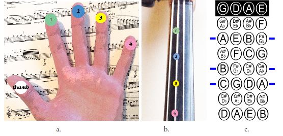
The basic method for playing a violin is as follows. The right hand is used for bowing and as the player moves their arm back and forth the bow will pull the string and cause it to vibrate and produce noise. The left hand's main job is to select which note on a string is placed by pressing down with one of the four fingers (the thumb is used to support the instrument). There are four strings (GDAE) which can be selected by rotating the left wrist slightly to adjust fingering or by changing the bow's angle to pull a different string. For a beginner using first position, each string has 5 possible sounds: one for the open string, 4 for each finger. The figures below show how fingering works and the possible notes for first position.
Figure 1. Violin Fingering Charts
For this project, the player's hand motions are tracked using accelerometers attached to a pair of gloves. The right and left hand control audio playback and string selection, respectively via I2C communication with the Raspberry Pi. Additionally, copper contact pads on the left hand allow for further note specification with fingering. A simple graphical interface on the Pi TFT enables the user to view information whether audio is playing and which note is selected.
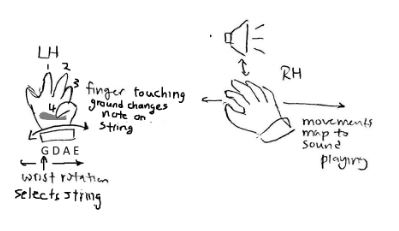
Figure 2. System Functionality Diagram
All audio was played using pygame.mixer. The sound files are .wav files taken from a youtube video (see References). Each note was clipped from the full video using the Audacity program. The .wav files were then exported to the Raspberry Pi from our computer. Once imported on to our Raspberry Pi, we assigned each sound file to a pygame.Sound variable and assembled a set of arrays, each representing a single violin string, with the proper notes. For example, the A_string array contains the variables for the following sound files: note_A4, note_B4, note_C5, note_D5, and note_E5. A larger array that encapsulates all of the string arrays was also created. Aptly named "violin",it organizes the string arrays in order from lowest to highest: G, D, A, and E - replicating a real violin. The first audio test was to experiment with PyGame and figure out the syntax to successfully generate sound. After reading the PyGame documentation, we used the following code to play a selected note:
violin[string_num][note_num].set_volume(volume)
violin[string_num][note_num].play(loops=-1)
In both lines, 'violin[string_num][note_num]' references the PyGame Sound object indexed by the current values of string_num and note_num. As explained above, the numbering system for our indices increases to higher notes (G=0, open note=0) and the notes for each string are determined by the standard violin as seen in the fingering chart in Figure 1c. The first line sets the playback audio to the value specified by the variable 'volume'. This parameter can range from 0 to 1 with 1 being full volume. The second line initiates audio playback and continuously loops the sound file.
Upon each main while-loop iteration, if the global loop counter was above ten then each accelerometers would be read. The movement data provided by them would then be used to determine "play_bool", a boolean value controlling if sound playback should be activated The accelerometer values would also set the magnitude of the aforementioned "volume" variable - set to 1.0(max) for a "big move" and 0.6 for a "small move". Determining whether the motion data gives us a big move or a small move is discussed further down (in the �accelerometers� section). If the movement values are large enough to call a motion either a "big move" or "small move"(e.g. The user is bowing), "play_bool" is set. After play_bool is determined an if-else statement checks its value to decide whether or not audio should be played. The same if statement checks the string_num variable to ensure that it has been set to something valid (eg string_num != -1, possible if a players string hand is in a dead zone(discussed later)) Should the if statement's code block be entered , the lines above are called. If the measured movement is considered too small to constitute bowing, the code branches into the else condition. Within this branch, we used pygame.mixer.Fadeout(100) to stop the actively playing sound with a 100 ms fade out to avoid harsh clipping noise. The fadeout function was chosen over the stop function because while practicing we noticed that slower movements of long bow strokes created occasional False readings for play_bool and produced repeated pauses in what should have been one continuous noise. Fadeout helped remove these pauses since it did not cut music off instantly. Although, using fadeout also creates a short echo when the user stops moving, we found that this sounded better overall than the random cutouts in the middle of bowing. We also used a "false counter" that keeps track of how many times in a row a value too low to constitute bowing has been produced when reading the accelerometer. By only fading sound out once this counter is high enough (greater than 1), we further reduce the effect of false readings. In a very early iteration of our code, we also tried a memory array that stored the value in "playing" for the past three iterations and used the majority to decide whether to play or stop music. We found that this method produced even longer echoes after the user stopped and so we discarded this idea.
There are a few other modifications we made to help with the cutout problem. Our primary way of adjusting the sensitivity was changing the accelerometer threshold. This was pretty finicky, and sometimes the same value would behave even worse after restarting the code. Our final accelerometer threshold value was determined mainly by experimentation to be high enough to reduce excess noise when a player is rather still but low enough to avoid cut-offs mid bow.
The hardware for this project consisted of two accelerometers and four copper contacts that act as active-low buttons. A picture and schematic of the full system is shown below in Figure 3. As previously stated, the four fingers on the left hand function exactly like the GPIO active-low buttons used for Lab 2 this semester. The contacts on the gloves serve as the high end of the switch and when pressed against the copper grounding plate shown in Figure 5 complete the circuit to drive the GPIO input low. The setup for these inputs followed the schematic from Lab 2 (Figure 4). Pull up resistors were enabled for the four GPIO ports used (BCM number ports 6, 13,19, and 26). Additionally, external resistors are used to protect the RPi pins. One of the piTFT buttons was also initialized to serve as a quit button.
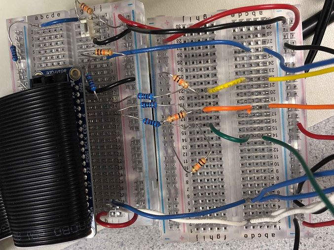
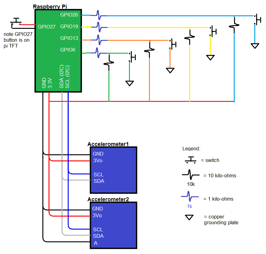
Figure 3. Full System Circuitry (left: actual image, right: schematic)
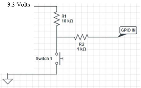
Figure 4. Active Low Button Schematic from Lab 2
The accelerometers have 4 main wires for connecting to the Raspberry Pi. Power (3.3V) and ground are provided from the RPi to both chips using the red and black wires in the image, respectively. Figure 7 in the "Accelerometer" section shows a close up of the two accelerometers. Additionally, clock and data lines (SCL and SDA) from the accelerometers are connected to the RPi's I2C clock and data lines located at pins 3 and 5 respectively. After ordering our two I2C accelerometers, we realized that the RPi only has one set of I2C ports for use. Initially, we thought this would become an issue when trying to concurrently read both accelerometers, however, we quickly resolved this after realizing that we can read the accelerometers virtually independently of each other by changing the device address. Changing the device address is as simple as grounding the Address pin (labeled) A on one of the accelerometers; this makes the address 0x1C while the other remains 0x1D. The connections shown in the diagram and schematic are direct without any other attachments.
Another major part of playing the violin is fingering. Fingering refers to the position the player presses on the string to create sounds of different frequencies, without it a violin would be limited to the number of strings on it. In real life, there are virtually infinitely many possible finger positions since the player can put their finger down anywhere on the string and create a sound. Valid finger positions are determined by the set frequency definitions in music and deviation from that position results in a high or low note. For our project we implemented a Guitar Hero-esque version of violin fingering where the actual position of the finger does not matter, only which finger is pressed. We also limited the violin notes to those of first position as shifting to a different position would require knowledge of the finger's relative location.
We simulated fingering in this project using a glove and several contact pads that function like active-low buttons as described in the "Schematic" section. The contact pads and wires were attached to the gloves using strips of electrical tape. One issue we ran into while testing was that the contact pads often shifted so that the conductive part was not centered with the user's finger. This made detecting the presses harder and our system less reliable. We found that this was partially due to the size of the gloves. People with larger hands can keep the glove taut and improve the electrical connection. Fixing the contact pads would be one of the tasks we would work on given more time. Possible changes are listed in the "Future Work" section. We went through two versions of the glove contact pads (shown in Figures 5 and 6). The first version used aluminum foil to add more surface area to our buttons, however, we realized that solder does not stick to aluminum and consequently the connections between the wires and foil were temperamental. We ended up redoing the glove with two-sided copper tape which worked adhered to the wire much better.
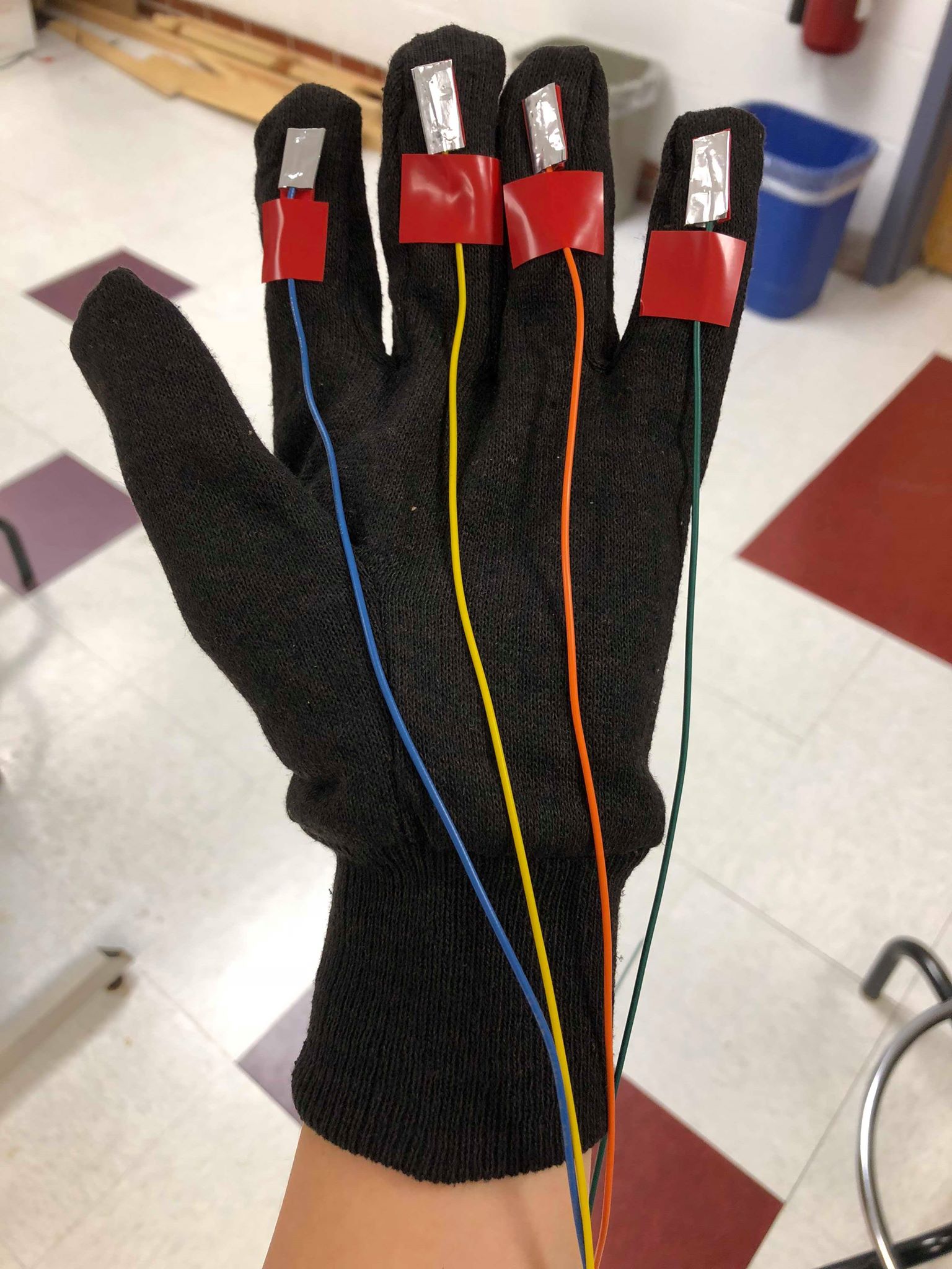
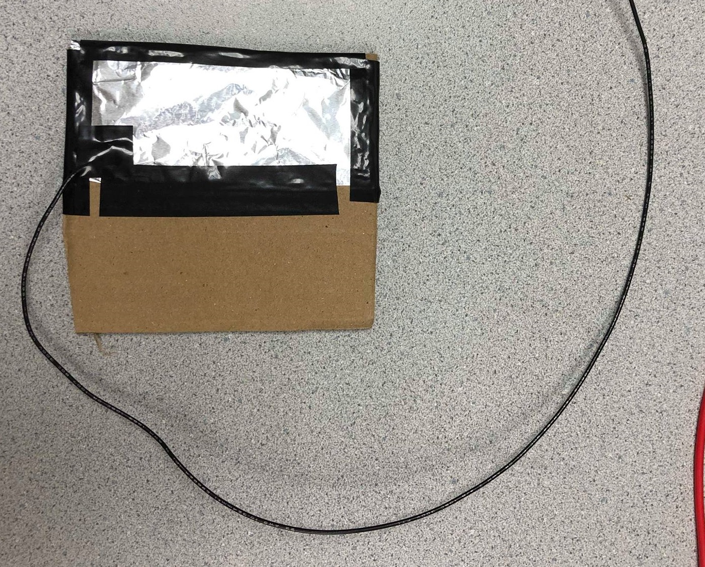
Figure 5. Version 1 of Left Hand Glove Using Aluminum
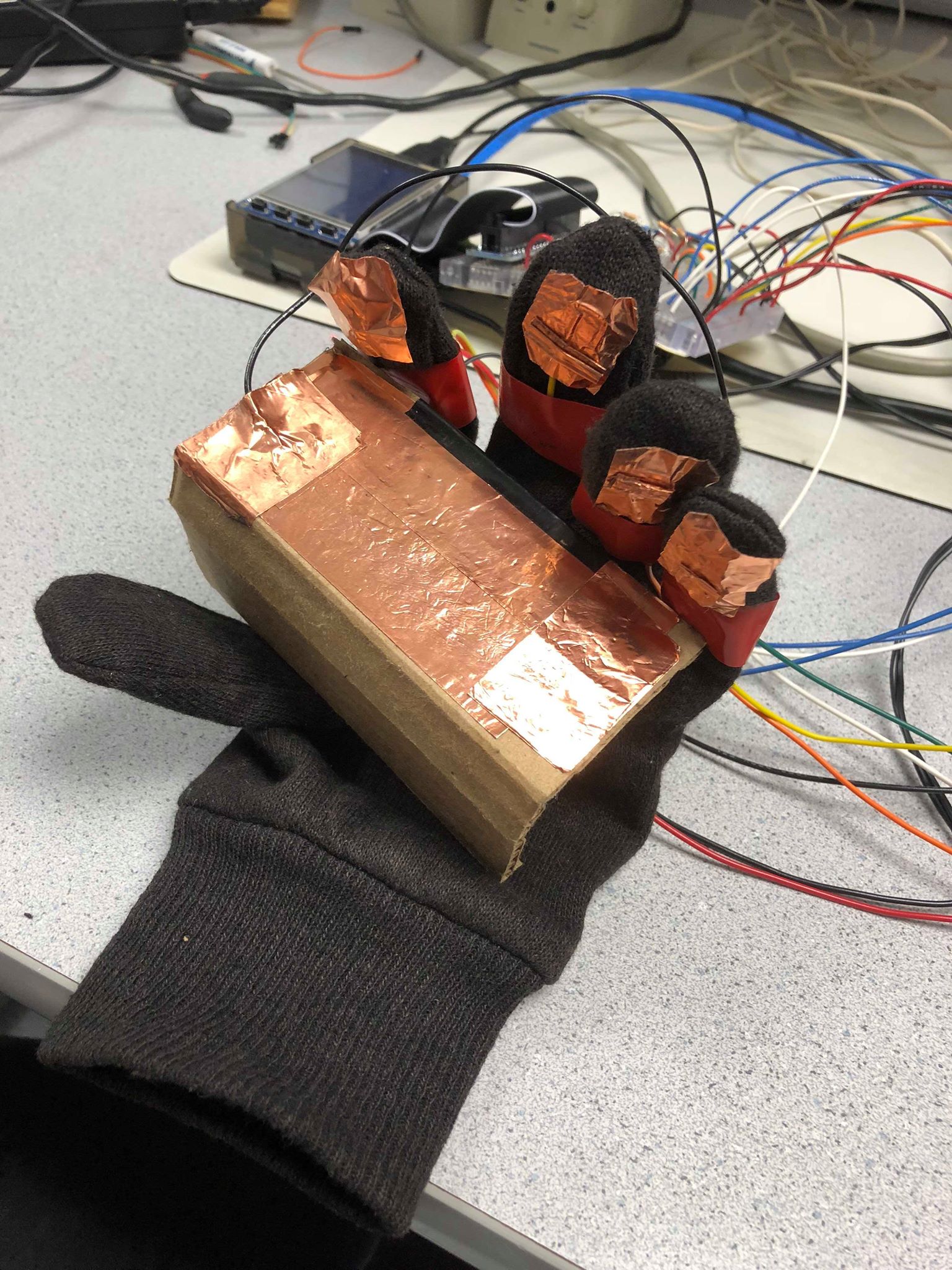
Figure 6. Version 2 of Left Hand Glove Using Copper Tape
Our initial tests for fingering actually used the piTFT buttons as we had already explored their functionality in previous labs. For example, we tested the code for audio generation with pygame using the piTFT buttons to toggle between four notes. We then expanded this to a six button version, four piTFT buttons and two external buttons, with the four piTFT buttons representing the four possible finger presses, one button to switch strings, and one button to play audio (a simulation of the bowing hand). Since we did not have to worry about the electrical connections of the buttons we were able to focus on the logic. We experimented with callback functions vs. polling for detecting button presses before deciding on the latter due to its simplicity. Once we knew our logic for the string and note selection were correct, we then switched to using contact pads.
The software for setting up the fingering detection used GPIO as described above. The only additional code needed to handle presses were simple if- elif statements conditioned on whether the GPIO pin inputs were low. Since when playing a violin pressing multiple fingers down would only cause the highest note to be played, the if-elif statements first check for the GPIO corresponding to the fourth finger (pinky finger) and then the third, second, first, and finally open string (no finger presses) when determining the value of note_num. Altough the contact pads are the most inconsistent part of our system, this is simply an issue in the physical connection.
Detecting movements in the user's hands is key to determining when the virtual violin should switch strings or play sound(bowing). These readings are taken from a pair of MMA8451 accelerometers that are each mounted to one glove, then connected to the Raspberry Pi (on SCL, SDA, 3.3V and GND) and communicated with via I2C. To access the accelerometers' registers via I2C, we made use of the smbus library that would allow us to use prebuilt functions that communicate to peripheral devices through an I2C bus. We first configured our program around a single accelerometer, as extending this to a second would be relatively simple. The default I2C address for the MMA8451 is 0x1D, which would need to be referred to every time an I2C transaction with the accelerometer was made. To set up the device for an I2C reading, we first require writing 0x01 and 0x00 to the CTRL1 and XYZ_DATA_CONFIG registers. This would need to be done each time we wanted to take an accelerometer reading, so the sequence of writes was stuck into the get_ready(DEV_ADDR) method. Any register read could then be performed with the bus.read_i2c_block_data(DEV_ADDR, REG_ADDR, SIZE) method (the reason for choosing the block read will become clear soon). We first ran a simple test that read out the WHOAMI register to verify that our physical connection was solid, and that the library was configured correctly. Once this was done, we were ready to take readings from the accelerometer's X_ACCEL, Y_ACCEL, and Z_ACCEL registers. We were able to forgo setting up the I2C get_ready(DEV_ADDR) for each register read by using the bus.read_i2c_block_data(DEV_ADDR, REG_ADDR, SIZE) method with the REG_ADDR set to 0x00 SIZE set to 7. Doing so would read the registers addressed from 0x00 to 0x06 at once into an array. 0x01 through 0x06 here are the six registers that contain all accelerometer sensor readings (2 for each axis).
Extending this program to the second accelerometer was simple enough with I2C. We simply needed to connect the wires for SCL, SDA, VCC, and GND to the same lines as the first accelerometer (see Figure 7). The two MMA8451 devices were identical, however, and as such would occupy the same I2C address. To alleviate this problem, one connected the second accelerometer's I2C Address Select Pin (labeled 'A') to ground, thus changing its device address to 0x1C. This new address would substitute the default 0x1D address (used for the first MMA8451) when interfacing with the second accelerometer in our code.
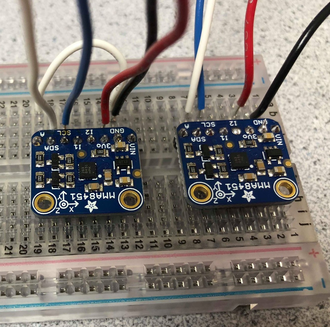
Figure 7. Accelerometer Testing Circuit
Accelerometers needed to undergo basic testing to determine value thresholds that needed to be exceeded to denote "movement". These were tested for in both the ideal case (accelerometers on a breadboard) and realistic case (accelerometers on gloves). When doing these tests we realized that the accelerometers' values were more useful as a position relative to its startup position, than an acceleration. The bowing hand requires movement to be detected on each cycle, however. As a result, we decided to only measure the change in accelerometer values between read cycles. This was relatively simple to implement in software, as we only needed to set the previously read value as an "offset" that the next read would be subtracted by. Taking the magnitude of that value gave us the change in accelerometer reading that we could use to accurately detect motion. This would not be implemented in the string-switching accelerometer, however, as the aforementioned reading of "position" was more valuable for that hand. By moving that accelerometer to a different "position", a different string would be set - which works better than a gesture (hand speed) doing the job. For each of these accelerometers, we also only needed to use the X-ACCEL reading, as most motions were able predominantly describable by changes in that axis.
Using these models, we tested for the thresholds we needed. For the bowing hand accelerometer we required finding what constituted enough motion to determine "playing". We found that a change in accelerometer value above magnitude 30 was ample for determining motion over stillness, even for an accelerometer placed on the user's hand. We added another threshold for this hand however - one that separated whether the user�s movement was a "big move" or a "small move", which affected only what volume the violin sound would be played at (discussed in "Audio". A change in accelerometer magnitude over 250 would make the movement received a "big move", with values under that but over 30 being denoted a "small move". The string switching hand also needed to have thresholds set. These thresholds would constrain the bowing hand to a region around its initial position that was then divided further into subregions - one for each string. Doing so would allow the user to turn their hand to a region to select their desired string - much like a dial. We first took the X-ACCEL values of extreme ends that we wanted the strings to be in, thus forming a range the enveloping constrained region (-200 to +200). We then divided that range of space into 4 subsections evenly for the 4 zones. This worked, although it felt clunky when playing. Adding an amount of dead space (referred to as dead zones in the code) wherein no string would be selected (string_num = -1) between the borders of the four subsections made this much more fluid. The width of this dead zone was tested for, eventually settling at around 20.
The accelerometers were mounted onto the gloves using a combination of electrical tape and thread (see Figure 8). To protect the user from direct contact with the pins a layer of electrical tape was placed underneath both accelerometers. Next, the accelerometers were sewn in place using the circular mounting holes at the end of the devices to loop thread through. The placement of the accelerometers are crucial for proper function. For example, at first the left hand accelerometer was placed too high. The top of the hand did not have as comfortable and large a range of motion to effectively use our thresholds for the strings so we had to remove the accelerometers and sew them on lower. In addition, we found that the thread was not enough support for the right hand accelerometer, so extra strips of electrical tape were used to secure it in place.
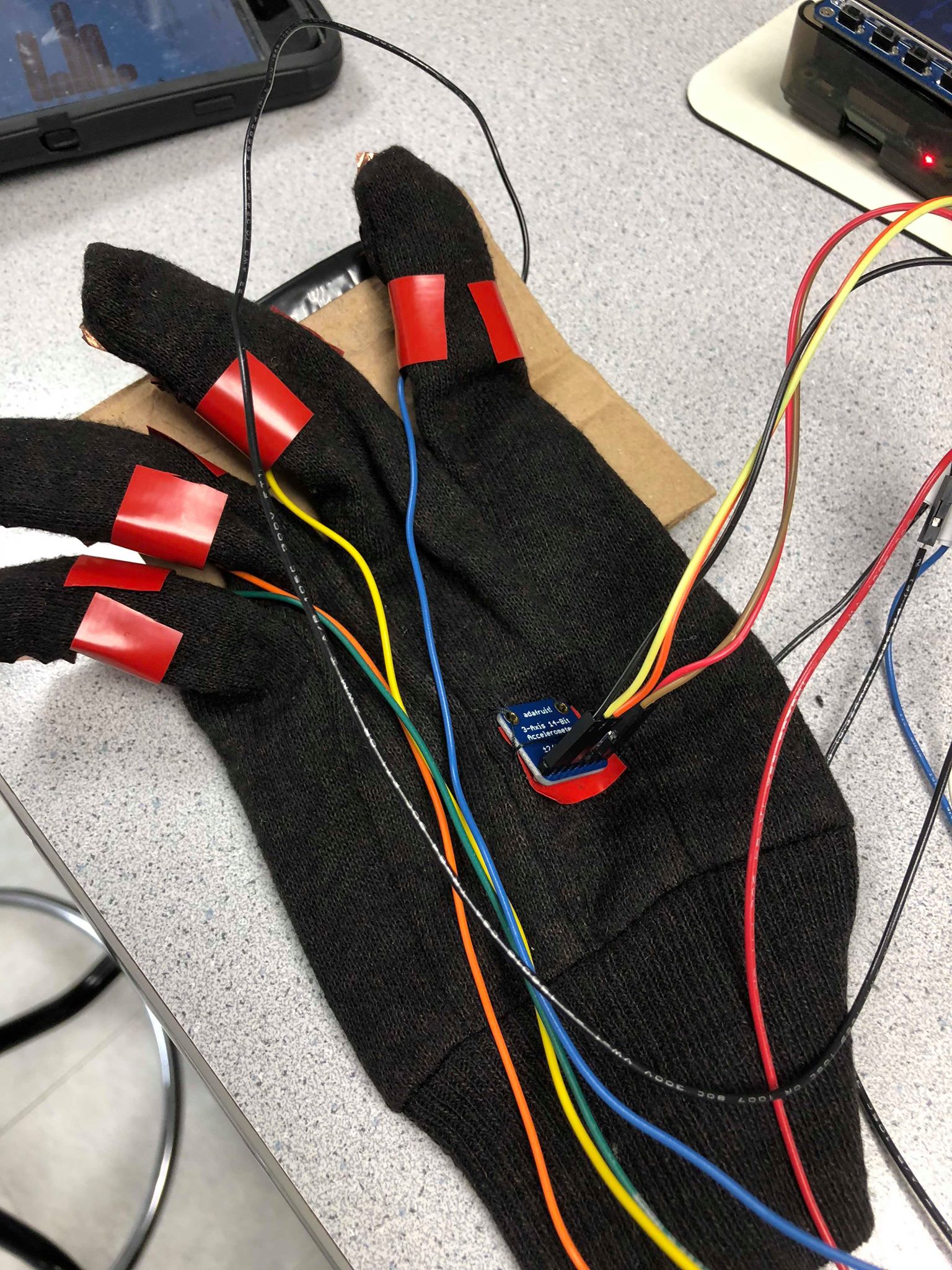
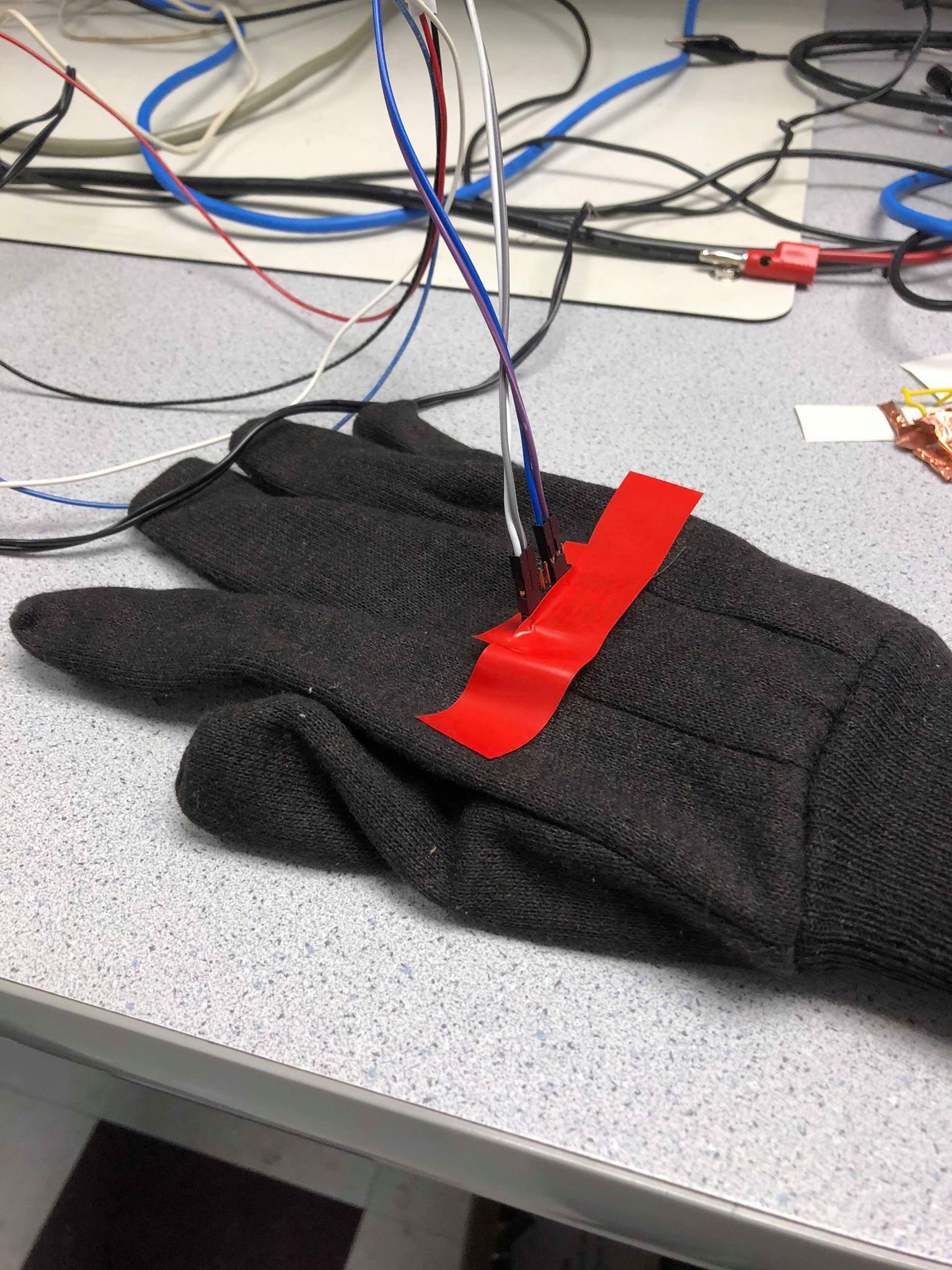
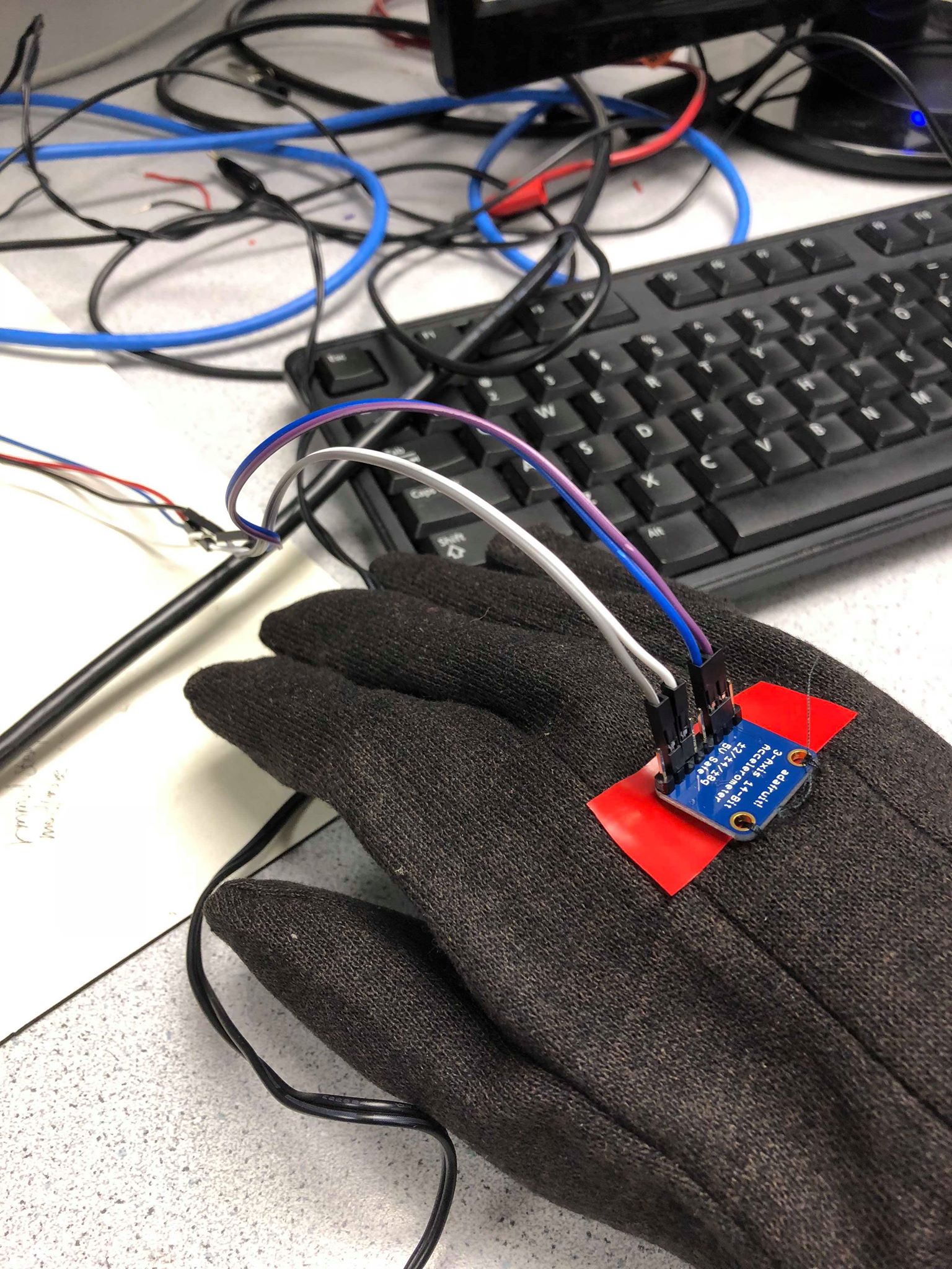
Figure 8. Final Accelerometer Mounting on Gloves (left: Left Hand, center: Right Hand with Tape, right: Right Hand Without Tape)
For testing, we mainly relied on print statements to check whether the correct string and finger press was detected or if the right hand accelerometer was working. This became a hassle while we were trying to debug the contact pads or string selection since the output would constantly stream on to the console. Additionally, we thought it would be bad coding practice to keep print statements during our final demonstration and if we removed them we would not be able to troubleshoot as easily. For these reasons, we designed a simple graphical user interface (GUI) that showed the same information as the print statements but in a cohesive fashion.
The GUI is composed of four lines each with four circles on them, representing the four violin strings and four potential finger notes per string. When unselected, all components are colored gray as shown in Figure 9 below. The strings will be highlighted blue when the left hand accelerometer's x-value is within that string's range; dead zones will return the string to the default gray. Similarly, detected finger presses will be shown on the current string as a cyan circle. Note that open string notes (no fingers pressed) will not show any cyan buttons. Additionally, a white circle appears in the bottom corner of the screen whenever play_bool is true (the right hand accelerometer's value has exceeded the thresholds). The images below show the selection of different strings and finger presses as well as a image with audio playing (Figure 11). For reference, the strings from the bottom of the screen to the top are G, D, A, and E and the string numbers increase from left to right.
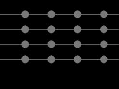
Figure 9. GUI with No Strings Selected
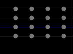
Figure 10. GUI with D-string Selected, No Audio
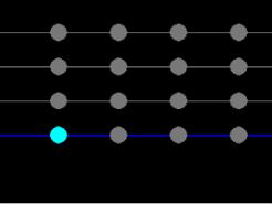
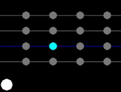
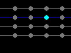
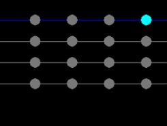
Figure 11. Monitor Screenshots of Notes Played on All Strings, the Image of the D-string shows audio playing
The display was implemented using pygame.draw.line and pygame.draw.circle. Two dictionaries hold each string/line and note/circle's screen coordinate with the key as the corresponding string or note number (i.e. G-string is string_num = 0, pinky finger press means note_num = 4). The color of the lines and circles are specified by comparing the value of string_num and note_num with the object's dictionary key to see whether or not they are selected. The white circle is only drawn when play_bool is true. Testing the GUI was mainly by trial and error for syntax, it was a good investment of our time and made debugging simpler and more intuitive.
Here is an image of the display shown on the piTFT.
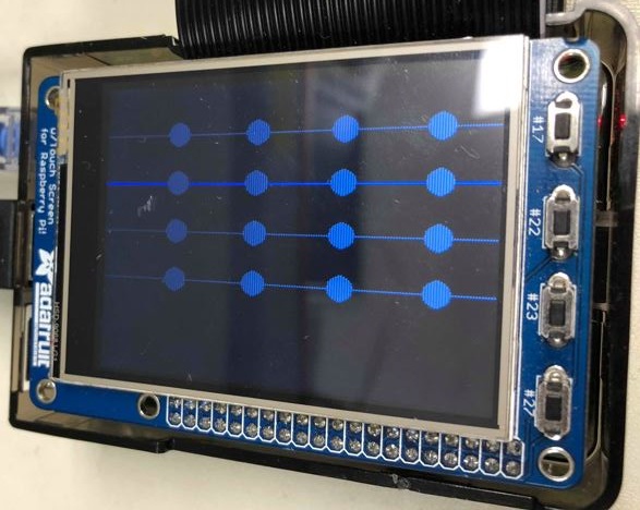
Figure 12. GUI on piTFT
Our project met all goals described in our initial project proposal and we were even able to add on extra features. The end product can successfully detect motion of the right hand and left hand to generate audio and switch strings, respectively. Our instrument can also distinguish between big and small moves of the right hand and alter the audio volume accordingly. Although the sensitivity of the left finger contacts restricts the playability of our instrument, this is a mechanical issue that can be easily fixed in the future. Overall, we are very satisfied with the stability of our final project especially for string selection.
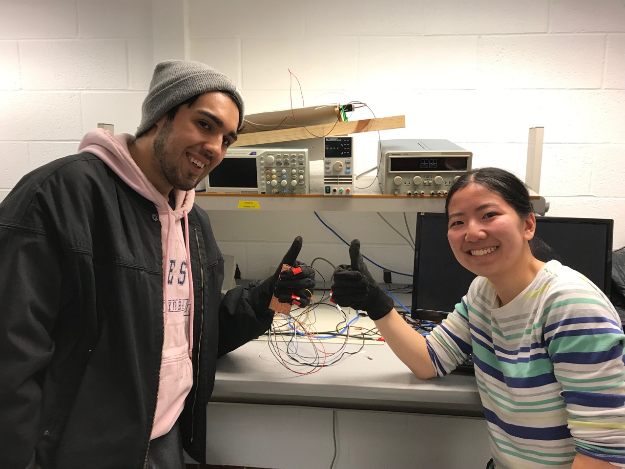
Due to the musical nature of our project, the best way to show our results is through a video. Click the video below to see our demonstration of the system.
Our team was successfully able to construct a working virtual instrument on the Raspberry Pi 3, utilising 2 MMA8451 accelerometers, the PyGame and smbus libraries, and some basic crafting materials. The instrument works reliably, although takes some practice to play actual music with, much like a real violin. Interfacing with our sensors and the Raspberry Pi 3 was relatively smooth for the duration of the project, although we did run into small issues when determining accelerometer thresholds. Calibrating accelerometers takes a lot of tuning, and our device could benefit from more advanced techniques that take advantage of other equipment such as gyros, magnetometers, and IMUs. Despite this, both bowing and string switching are very usable after some operation. Altogether, this device is a fun gadget to play around with and we believe borders the direction that cutting edge technology is headed towards, especially applications such as robotics and virtual reality.
Although our project accomplished all the goals of our initial plan and a few extensions, there are still a few modifications we would have explored given more time. The only aspect of our current project that we would modify are the copper left hand finger contacts. The poor connections between the finger contacts and grounding plate were the largest disruption to our project and caused the Raspberry Pi to occasionally miss detecting finger presses. After redoing these contacts repeatedly, we found that one finger with a soldered underlying wire had the best connection to the copper surface due to the bump created by the solder. If we had more time, we would have tried soldering the other wires to improve our accuracy in detecting finger presses.
Another extension that we could have added to this project was implementing Professor Land's string synthesis code. We considered swapping out the wav files used for the actual note sounds in favor of generating our own audio using FM synthesis, but decided that with our time constraint the wav files met our goals. After noticing the movement limitations imposed by our current glove wiring, future work for this project could also look into using bluetooth to pass the accelerometer data from the glove to Raspberry Pi wirelessly. Bluetooth would allow more freedom to move both hands without worrying about accidentally disconnecting a wire.
Now with some practice you too can be a violin virtuoso! We would like to thank Professor Skovira and the other course staff for a great semester.
Both members worked on all the code together including the scripts for implementing I2C communication, playing audio, and reading the accelerometers. Erika created the first version of the glove contact pads and sewed the accelerometers onto the gloves. The GUI was also written by Erika. Joshua redid the gloves with copper tape to create version 2 of the left hand. Both members worked together to calibrate the system and find ideal accelerometer threshold values.
# Erika Yu (ejy25) and Joshua Diaz (jd794)
# import GPIO and pygame
# LEGEND : 1= BOWING HAND
#                  2= LEFT HAND
import pygame
import RPi.GPIO as GPIO
import time
import smbus
import os

### TFT SETUP
os.putenv('SDL_VIDEODRIVER', 'fbcon')
os.putenv('SDL_FBDEV', '/dev/fb1')
os.putenv('SDL_MOUSEDRV', 'TSLIB')
os.putenv('SDL_MOUSEDEV', '/dev/input/touchscreen')

# setup pygame
pygame.init()
pygame.mouse.set_visible(False)
screen = pygame.display.set_mode((320,240))
pygame.mixer.init()
# setup GPIO and buttons
GPIO.setmode(GPIO.BCM)
GPIO.setup(27, GPIO.IN, pull_up_down=GPIO.PUD_UP)
GPIO.setup(26, GPIO.IN, pull_up_down=GPIO.PUD_UP)
GPIO.setup(19, GPIO.IN, pull_up_down=GPIO.PUD_UP)
GPIO.setup(13, GPIO.IN, pull_up_down=GPIO.PUD_UP)
GPIO.setup(6, GPIO.IN, pull_up_down=GPIO.PUD_UP)
GPIO.setup(21, GPIO.IN, pull_up_down=GPIO.PUD_UP)

# initialize variables for string, note, and playing condition
string_num = 0 #0:G 1:D 2:A 3:E
note_num = 0 # 0:Open 1:first_finger 2:second_finger 3:third_finger 4:forth_

string_playing = 0
note_playing = 0
playing = False

# define colors
BLACK = 0,0,0
WHITE = 255,255,255
GRAY = 120,120,120
BLUE = 0,0,255
CYAN = 0,255,255

# dictionaries for display
note_pos = {'1':70,'2':140,'3':210,'4':280}
string_pos = {'3':40,'2':80,'1':120,'0':160}

# import sound files for all 4 stirngs
note_G3 = pygame.mixer.Sound('../Final_PJ/Notes/G3.wav')
note_A3 = pygame.mixer.Sound('../Final_PJ/Notes/A3.wav')
note_B3 = pygame.mixer.Sound('../Final_PJ/Notes/B3.wav')
note_C4 = pygame.mixer.Sound('../Final_PJ/Notes/C4.wav')

note_D4 = pygame.mixer.Sound('../Final_PJ/Notes/D4.wav')
note_E4 = pygame.mixer.Sound('../Final_PJ/Notes/E4.wav')
note_F4 = pygame.mixer.Sound('../Final_PJ/Notes/F4.wav')
note_G4 = pygame.mixer.Sound('../Final_PJ/Notes/G4.wav')

note_A4 = pygame.mixer.Sound('../Final_PJ/Notes/A4.wav')
note_B4 = pygame.mixer.Sound('../Final_PJ/Notes/B4.wav')
note_C5 = pygame.mixer.Sound('../Final_PJ/Notes/C5.wav')
note_D5 = pygame.mixer.Sound('../Final_PJ/Notes/D5.wav')

note_E5 = pygame.mixer.Sound('../Final_PJ/Notes/E5.wav')
note_F5 = pygame.mixer.Sound('../Final_PJ/Notes/F5.wav')
note_G5 = pygame.mixer.Sound('../Final_PJ/Notes/G5.wav')
note_A5 = pygame.mixer.Sound('../Final_PJ/Notes/A5.wav')
note_B5 = pygame.mixer.Sound('../Final_PJ/Notes/B5.wav')

# Set string arrays as collections of notes
G_string = [note_G3, note_A3, note_B3, note_C4, note_D4 ]
D_string = [note_D4, note_E4, note_F4, note_G4, note_A4 ]
A_string = [note_A4, note_B4, note_C5, note_D5, note_E5 ]
E_string = [note_E5, note_F5, note_G5, note_A5, note_B5 ]

#Set violin array as collection of strings
violin = [G_string, D_string, A_string, E_string]

# Set up accelerometer
CHANNEL = 1

DEV_DEFAULT_ADDR = 0x1D
DEV_SECOND_ADDR = 0X1C

REG_CTRL1 = 0x2A
REG_XYZ_DATA_CFG = 0x0E
REG_STATUS = 0x00

REG_OFF_X= 0x2F
REG_OFF_Y = 0x30
REG_OFF_Z = 0x31

bus = smbus.SMBus(CHANNEL)
MODE_CONFIG = 0x01
DATA_CONFIG = 0x00

# function to prepare accelerometers
def get_ready(DEV_ADDR):
        bus.write_byte_data(DEV_ADDR, REG_CTRL1, MODE_CONFIG)
        bus.write_byte_data(DEV_ADDR, REG_XYZ_DATA_CFG, DATA_CONFIG)

# function to read data from one accelerometer given device address and initial x and z values
def read_accel(DEV_ADDR, init_accel_x, init_accel_z):
        data = bus.read_i2c_block_data(DEV_ADDR, REG_STATUS, 7)
        x_accel =((data[1] *256 + data[2]) >> 4) - init_accel_x
        if(x_accel > 2047):
                x_accel -= 4096
        y_accel = (data[3] *256 + data[4]) >> 4
        if(y_accel > 2047):
                y_accel -= 4096
        z_accel = ((data[5] *256 + data[6]) >> 4) - init_accel_z
        if(z_accel > 2047):
                z_accel -= 4096
        return {'x':x_accel, 'y':y_accel, 'z':z_accel}

# initialize variables for accelerometer data
counter = 0
init_accel_x1 = 0
init_accel_x2 = 0
init_accel_z2 = 0

small_move_x1 = False
big_move_x1 = False
offset_x1 = 0
offset_x2 = 0
offset_z2 = 0
false_bow_count = 0
volume = 1.0

screen.fill(BLACK)
# Polling loop
while(1):
        get_ready(DEV_DEFAULT_ADDR)
        get_ready(DEV_SECOND_ADDR)
        time.sleep(0.2)
        if( not GPIO.input(27)): # quit button
                break

        # poll for left finger presses
        if( not GPIO.input(6)):
                note_num = 4
        elif( not GPIO.input(13)):
                note_num = 3
        elif( not GPIO.input(19)):
                note_num = 2
        elif( not GPIO.input(26)):
                note_num = 1
        else:
                note_num = 0

        # small calibration period
        if(counter == 10):
                init_accel = read_accel(DEV_DEFAULT_ADDR,0,0)
                init_accel_x1 = init_accel['x']
                init_accel = read_accel(DEV_SECOND_ADDR,0,0)
                init_accel_x2 = init_accel['x']
                init_accel_z2 = init_accel['z']
                counter += 1
        # read both accelerometers
        elif(counter>10):
                accel = read_accel(DEV_DEFAULT_ADDR,init_accel_x1,0)
                x_acc = abs(accel['x'])
                accel = read_accel(DEV_SECOND_ADDR,init_accel_x2,init_accel_z2)
                x_acc2 = (accel['x'])
                z_acc2 = abs(accel['z'])

                # BOWING HAND ACCELEROMETER CHECKS
                #check for change in x1
                if(abs(x_acc-offset_x1) > 250):
                        small_move_x1 = False
                        big_move_x1 = True
                        volume = 1.0
                elif(abs(x_acc-offset_x1) > 30):
                        small_move_x1 = True
                        big_move_X1 = False
                        volume = 0.6
                else:
                        small_move_x1 = False
                        big_move_x1 = False

                # FINGERING HAND ACCELEROMETER CHECKS
                #check for change in x2 and in z2
                if(x_acc2 > 200): #E-STRING
                        string_num = 3
                elif(x_acc2 > 170): #DEAD ZONE
                        string_num = -1
                elif(x_acc2 > 20): #A-STRING
                        string_num = 2
                elif(x_acc2 > 0): #DEAD ZONE
                        string_num = -1
                elif(x_acc2 > -200): #D-STRING
                        string_num = 1
                elif(x_acc2 > -220): #DEAD ZONE
                        string_num = -1
                else: #G-STRING
                        string_num = 0
                #print(x_acc2)

                offset_x1 = x_acc
        else:
                counter += 1


        play_bool = small_move_x1 or big_move_x1
        if (play_bool and string_num != -1): # play sound
                playing = True
                false_bow_count = 0
                violin[string_num][note_num].set_volume(volume)
                violin[string_num][note_num].play(loops=-1)
                if(string_playing!=string_num or note_playing!=note_num):
                        violin[string_playing][note_playing].stop()
                string_playing = string_num
                note_playing = note_num
                pygame.draw.circle(screen, WHITE, [20,220], 15)

        # no movement, don't play sound
        else:
                pygame.draw.circle(screen, BLACK, [20,220], 15)

                false_bow_count += 1
                if(false_bow_count >= 2):
                        playing = False
                        pygame.mixer.fadeout(100)

        # draw and display TFT GUI
        for str_num, str_coord in string_pos.items():
                if(str(string_num) == str_num):
                        pygame.draw.line(screen, BLUE, [0, int(str_coord)], [320,int(str_coord)], 1)
                else:
                        pygame.draw.line(screen, GRAY, [0, int(str_coord)], [320,int(str_coord)], 1)
                for notes_num, note_coord in note_pos.items():
                        if(str(note_num) == notes_num) and (str(string_num) == str_num):
                                pygame.draw.circle(screen, CYAN, [int(note_coord), int(str_coord)], 10)
                        else:
                                pygame.draw.circle(screen, GRAY, [int(note_coord), int(str_coord)], 10)

        pygame.display.flip()