Pi SmartHome
ECE 5725: Embedded Operating Systems (Fall 2018)
Anant Desai & Rick Lin
Pi SmartHome in Action
Introduction
Emphases have been made to address energy conservation issues in recent years, as people around the globe start to realize the importance of limited energy resources. Engineers have been working on connected home and smart home products in the form of Internet of Things (IoT) that help with energy-conscious lifestyles. We proposed a smart home mockup system that automatically controls the lights and fans in a room according to the ambience and switches off the appliances when the room becomes empty. We would like to demonstrate that adaptive smart controls help cut down the energy cost by effectively detect the occupancy status of a room.

Project Objective
The project is a Smart Home system. This means that it consists of several sensory inputs and processes them to perform “smart” tasks. In this case, the tasks consist of providing lighting and cooling to the users. The project system consists of four input sources: a video camera, a temperature sensor, an ambient light sensor, and buttons for manual user input to override the automatic features. The temperature sensor and light sensor provide details about the environment. The video camera uses openCV, a computer vision library, to detect the direction of motion and keep track of the occupancy of a room. The video camera is meant to be placed near a doorway. The video camera runs off a separate processor, a Raspberry Pi Zero, which communicates via Bluetooth to the main Raspberry Pi 3 that reads the other sensory inputs. Based on these inputs, this Raspberry Pi 3 outputs signals to the light and fan to either turn them on or off.
Design and Testing
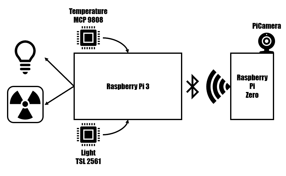
The schematic diagram for our smart home system
Light/Temperature sensor: The light and temperature sensors were both separately connected to the appropriate input pins for I2C. This meant that the appropriate SCK, SDL, VCC, and GND lines were connected. First, we tested the light sensor. We found an example online for the particular sensor we bought, demonstrating how to communicate with the sensor and read the sensors value via I2C. Once the light sensor seemed to be producing reasonable values (which we determined by either blocking the light or adding additional light with a phone’s light), we disconnected it to try the same thing with the temperature sensor. We tested the temperature sensor by similarly increasing and decreasing the temperature by breathing or blowing on the sensor. When we verified that the temperature sensor was producing reasonable values, we combined both sensors on the same SDL data like to make sure the I2C’s addressing was working correctly with multiple sensors on the data line. This, again, worked fine. Then we make a simple script that continuously monitored the environment’s light level and temperature and displayed these values to the console. This basic script would eventually become the backbone of the final decision-making script that we ran during the demo.
Bluetooth: To enable bluetooth communication, we used a python library called bluedot. There were simple instructions to make the Raspberry Pi 0 and Raspberry Pi 3 discoverable to allow one of them to find and pair with the other one. From there, there was an API called Bluetooth Comm API which allowed for easy creation of a bluetooth client, which sends information over bluetooth to a bluetooth server. Initially, for testing, we ran the bluetooth client off of the raspberry pi 0 and simply had it transmit a simple string to see if the bluetooth server, running on the raspberry pi 3, would be able to receive and process the bluetooth signal. Once this had succeeded, we proceeded to integrate the bluetooth client code into the openCV code such that occupancy information would be transmitted over bluetooth. We verified using the simple bluetooth server on the raspberry pi 3 that the correct information was being passed over the bluetooth communication. Once this was verified, we integrated the bluetooth server code into the main integrated script that performed the decision making based on sensor inputs. The simple bluetooth server and simple bluetooth client python files are also provided in the code appendix.
PiCamera and OpenCV: The PiCamera was connected to Raspberry Pi Zero board via the specialized camera connector. An adapter was used to convert the coarser pitch used by the camera board to a finer pitch used by Raspberry Pi Zero. We also enable the camera connection in Pi configuration menu to finish the installation of PiCamera. For the purpose of our project, we utilized OpenCV to carry out object detection and thus count the occupancy in a room; therefore, we installed a pre-compiled version of the OpenCV library to deal with the detection. Our movement tracking algorithm contain a several key features, but they all supported the main function of our system: detecting the direction of movements and resolve them to either entering the room or leaving the room. To detect movements, the algorithm first needed to calibrate its vision and set a baseline environment as a reference frame. The algorithm can then carry out background subtraction and highlight the difference in pixel values should there be a new object moving across the frames. We set both a left and a right threshold to decide the direction of movements. The top left corner of the “enclosing rectangle” of the moving object was used for this purpose. If the corner moved in a swift motion to the right (with increasing x) and crossed the right threshold, then the person “left” the room. On the other hand, if the corner moved in a swift motion to the left and crossed the left threshold, then the person “entered” the room. We also ignored the objects that were not of interests, meaning that if the objects were not crossing between the thresholds then we should not pick them up. Note that because we were not tracking the objects outside of the thresholds, we would not be able to trigger the detected action where the corner crossed into the thresholds. To address this specific issue, we created a buffered zone extending from the thresholds in order to accommodate such movements. Currently, the left and right thresholds lied approximately a quarter width from the edges of the frame. We also considered the situation where two people were trying to enter or leave the room at roughly the same time. As the algorithm was only able to process one object at a time, we chose to track the first object in the object set and filtered out any activity that was within the 1-second interval from the previous "enter” or “leave” incident. These measures further increased our accuracy when detecting the change of occupancy in a room. Since we connect Raspberry Pi Zero over the bluetooth, and that bluetooth communication had its latency, we minimized the burden on the communication channel by only transmitting the increment/decrement signals to update the occupancy and left all the calculations up to the host, which was our main Raspberry Pi board.
Fan and LED: We utilized a CPU fan and a LED backlight panel as our cooling and light sources in the smart home mockup system. The fan was rated at 15V, but for the purpose of our system we only supplied the fan with 5V source and let it drew approximately 60mA. We powered the LED panel with the 5V source and it drew 15mA. Instead of powering the devices directly off from the GPIO outputs, which were not capable of supplying these devices with adequate power, we used MOSFET transistors as a switch to turn on and off the devices. The transistors were controlled by the GPIO outputs. On the occasion where the room was occupied, the light and the fan turned on when the sensor read that the ambience light level was lower than 200 and the temperature was higher than 26 degrees Celsius respectively. When the room was empty (occupancy was 0), then regardless of the sensor readings both the fan and the light were turned off. This was to conserve the energy when no one was in the room.
User Interface: The TFT screen was used to display the sensor readings and the control mode (manual/auto). Additionally, we designated the buttons on the TFT board to serve as manual override to turn on and off the light and the fan under auto mode. However, once the automatic control was overridden, the system then entered the “manual” mode where sensor readings no longer affected the devices. But once the room occupancy dropped to 0, the auto mode again kicked in.
Pictures
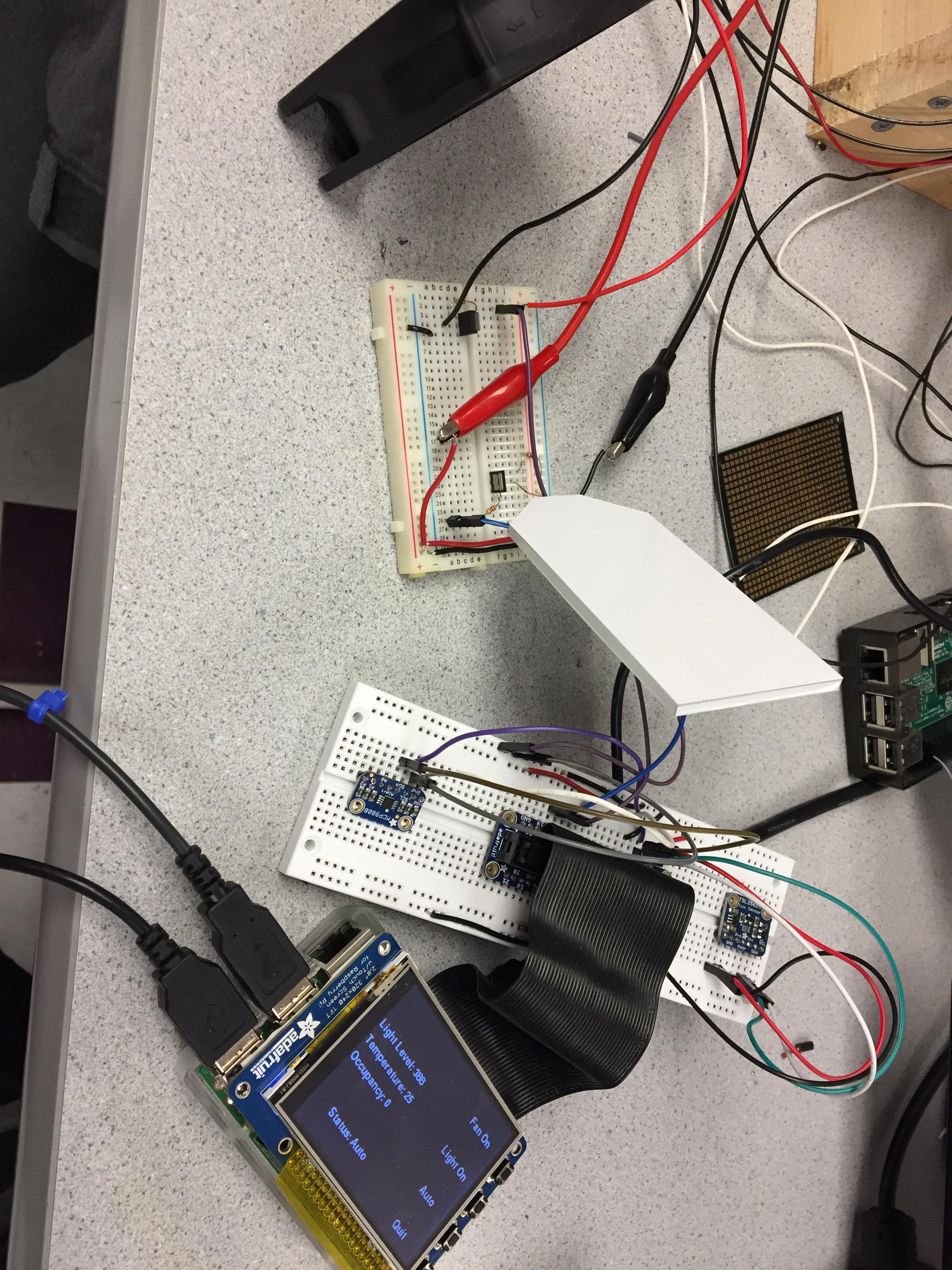
Figure 1. The main host of our smart home system -- using a Raaspberry Pi board.
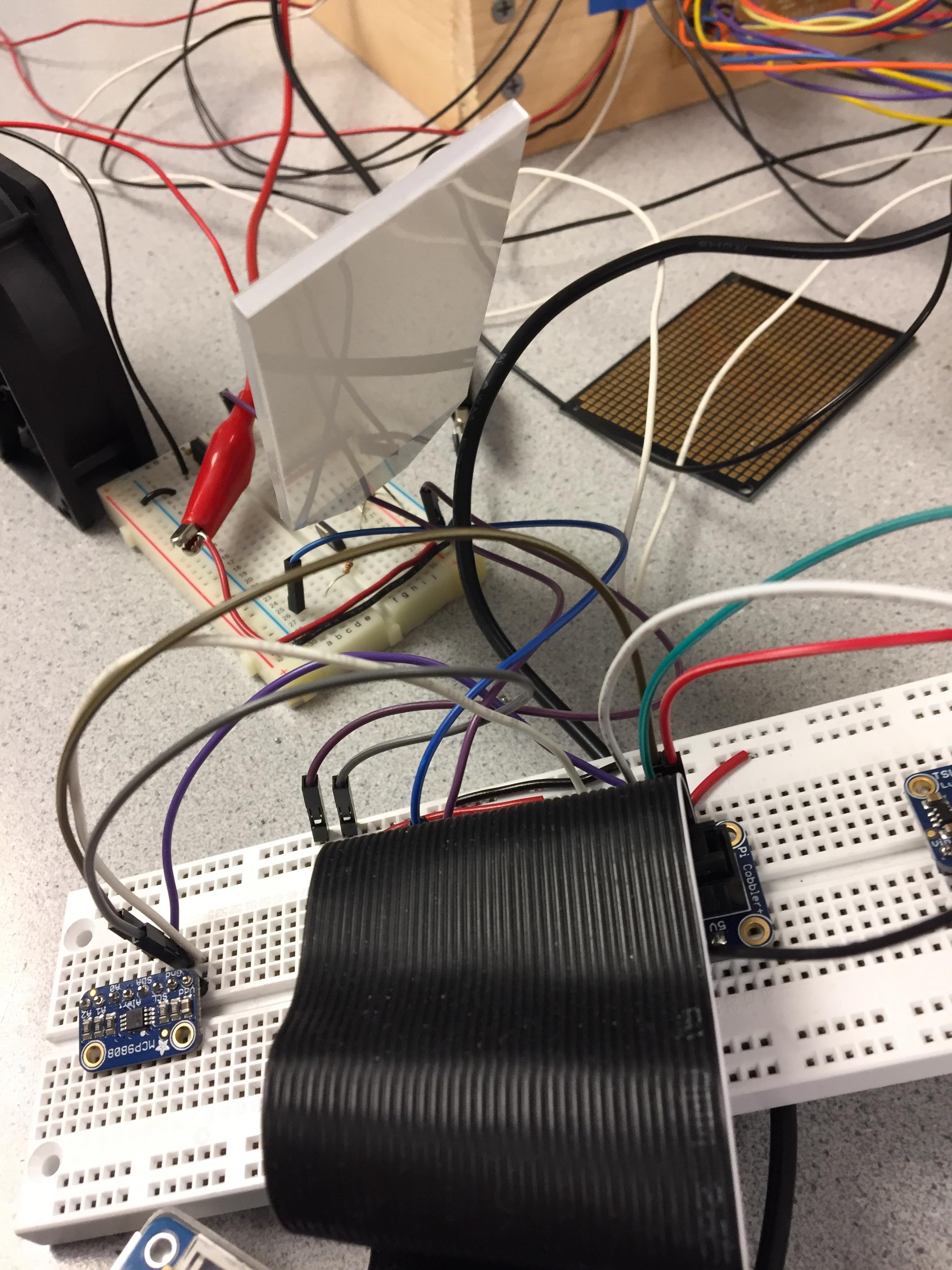
Figure 2. The associated circuitry for our host system, connecting different devices and sensors.
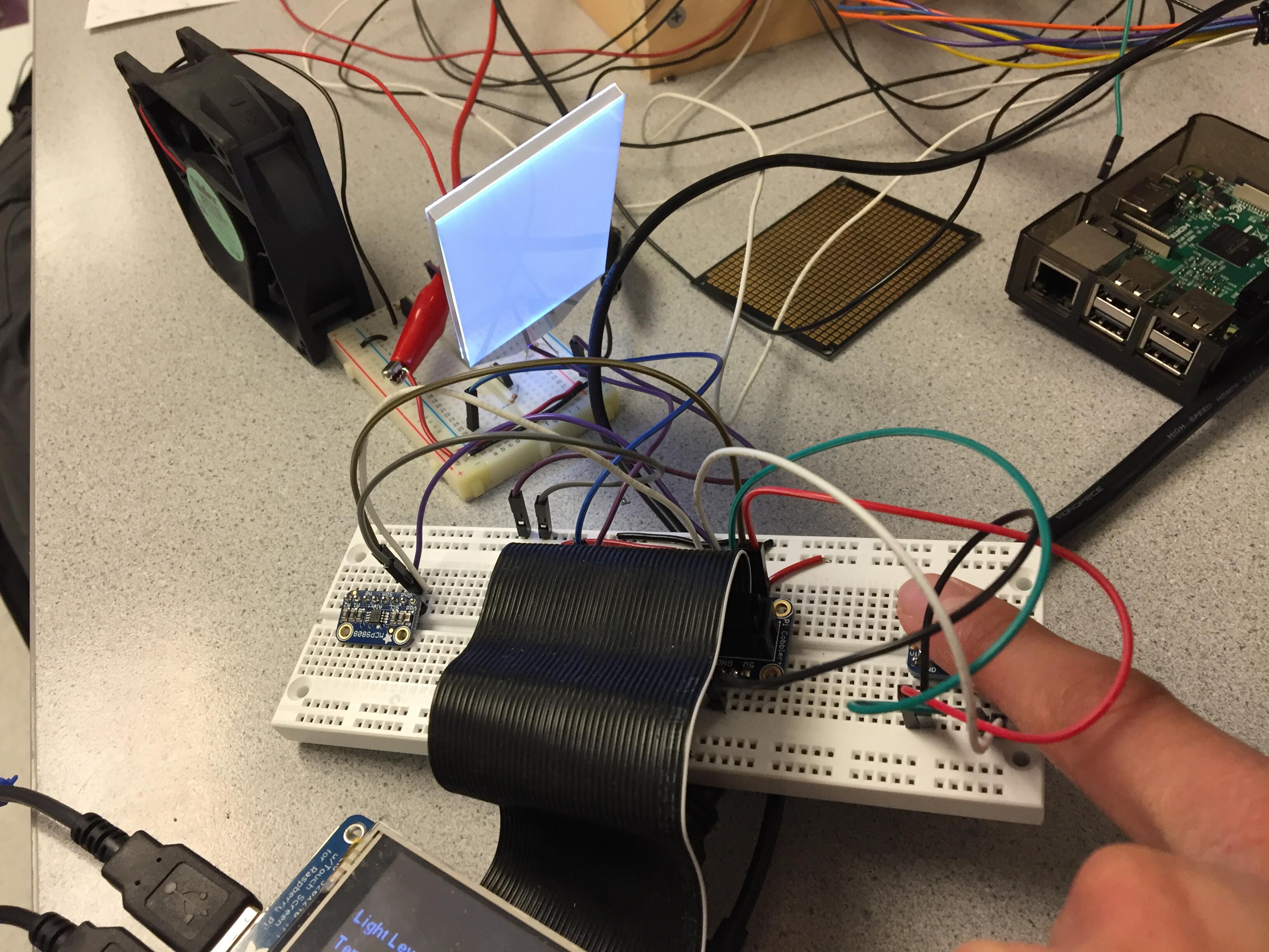
Figure 3. LED panel, fan, and sensors.
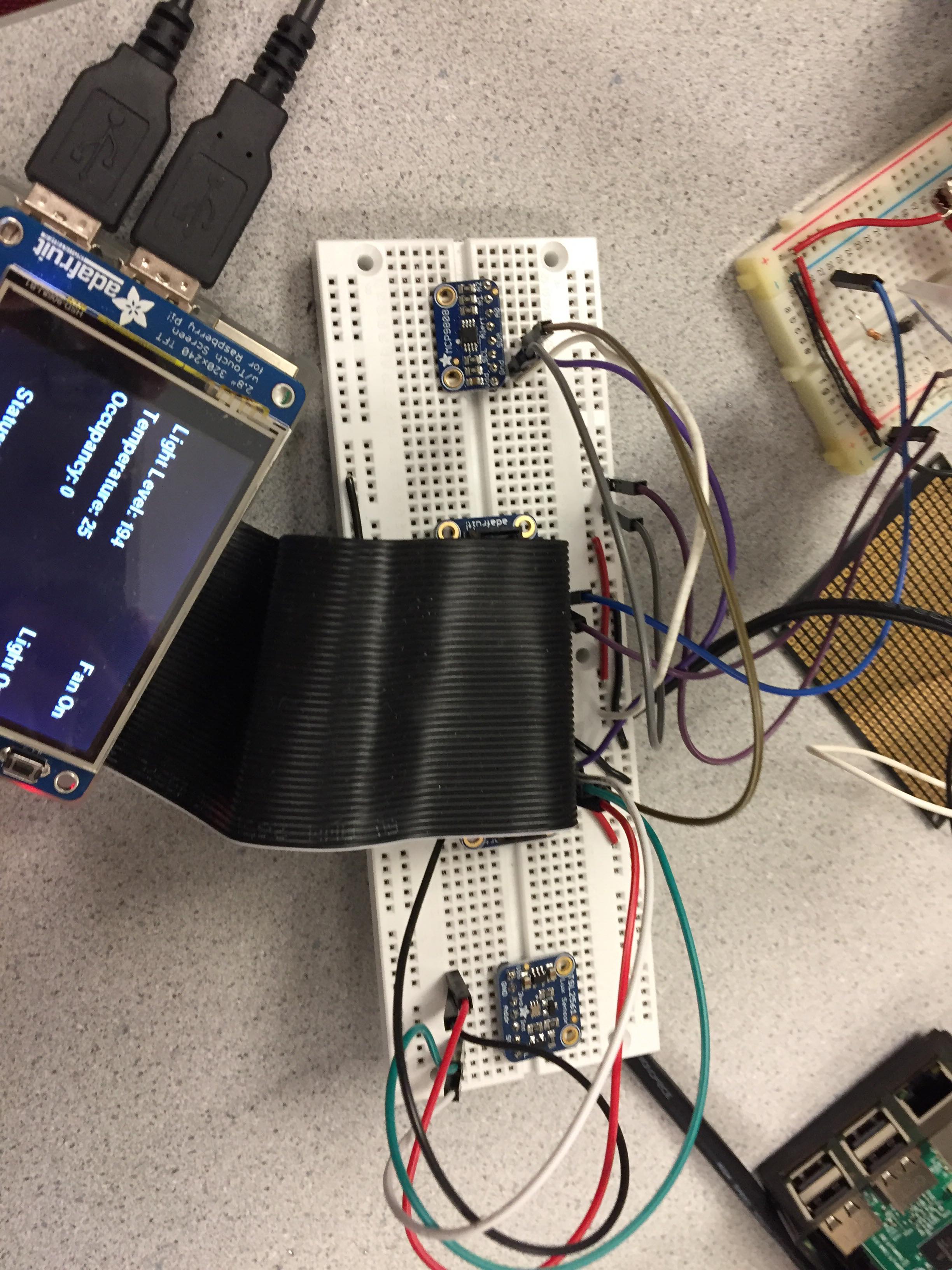
Figure 4. We arranged our sensors together with the GPIO header on a breadboard.
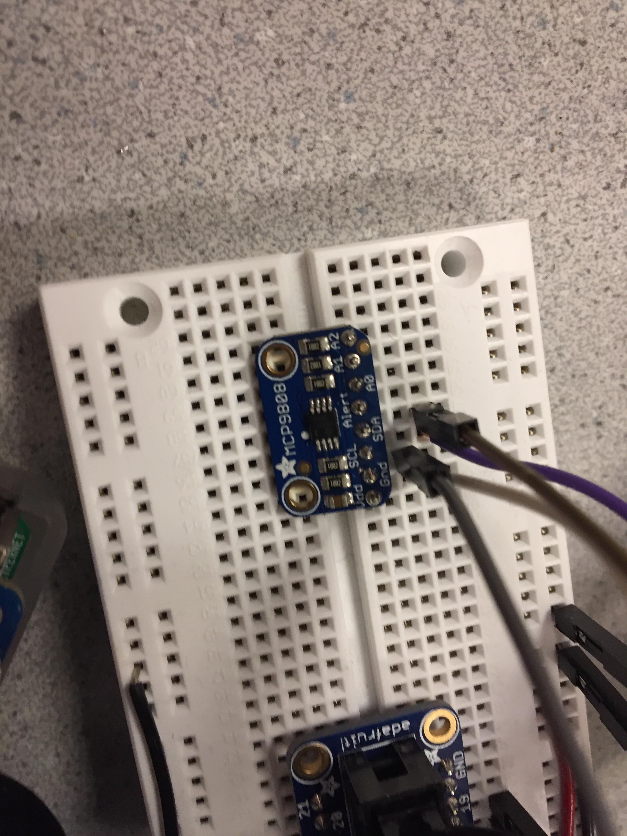
Figure 5. Temperature sensor MCP9808.
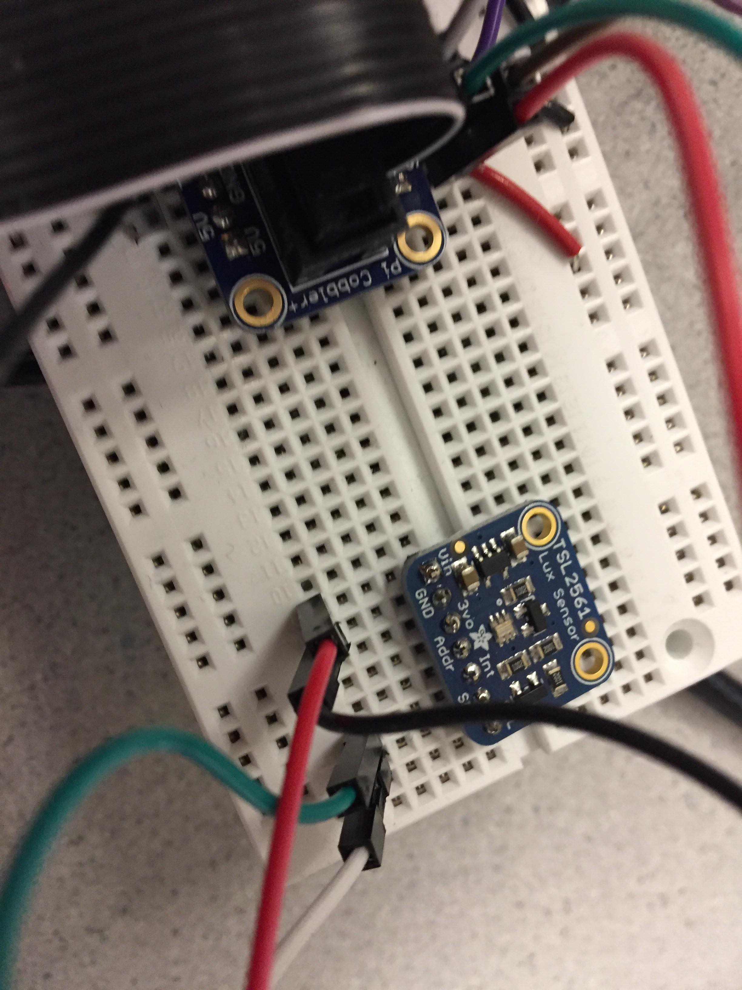
Figure 6. Light/Lux sensor TSL2561.
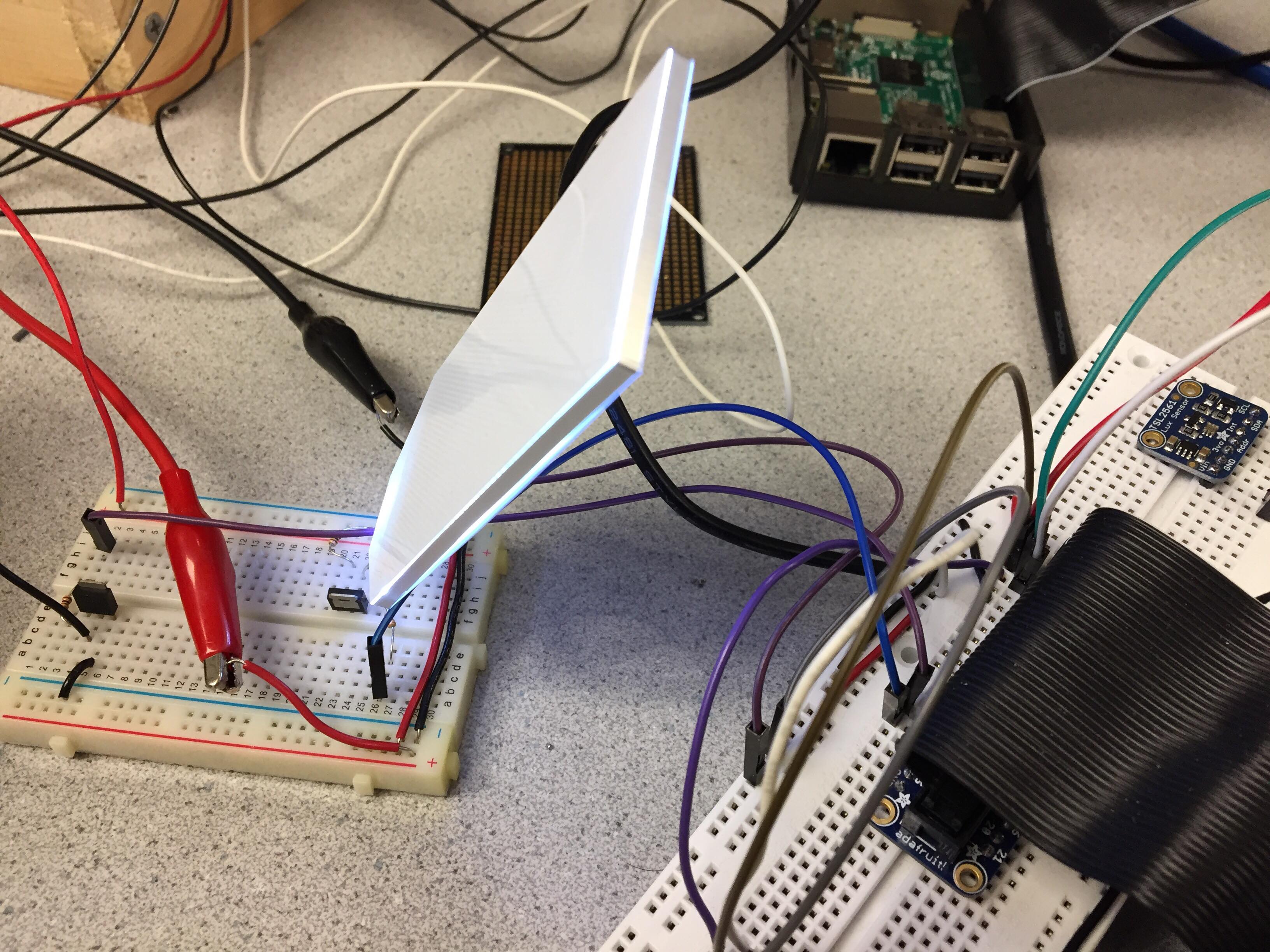
Figure 7. Light panel lighting up.
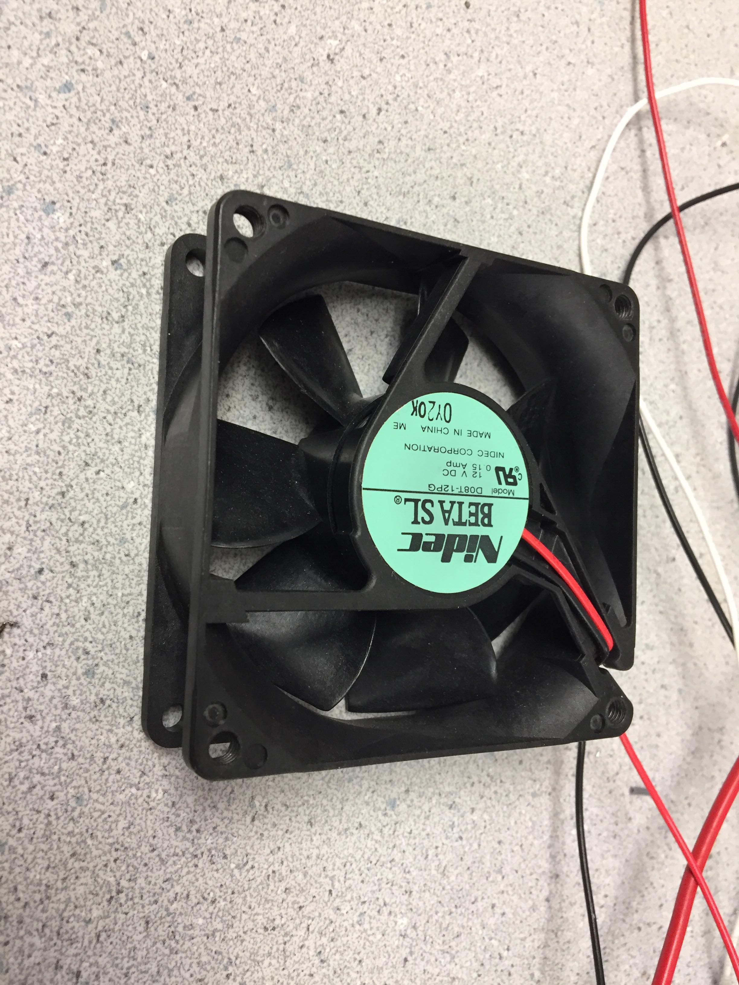
Figure 8. The fan in a idle state.
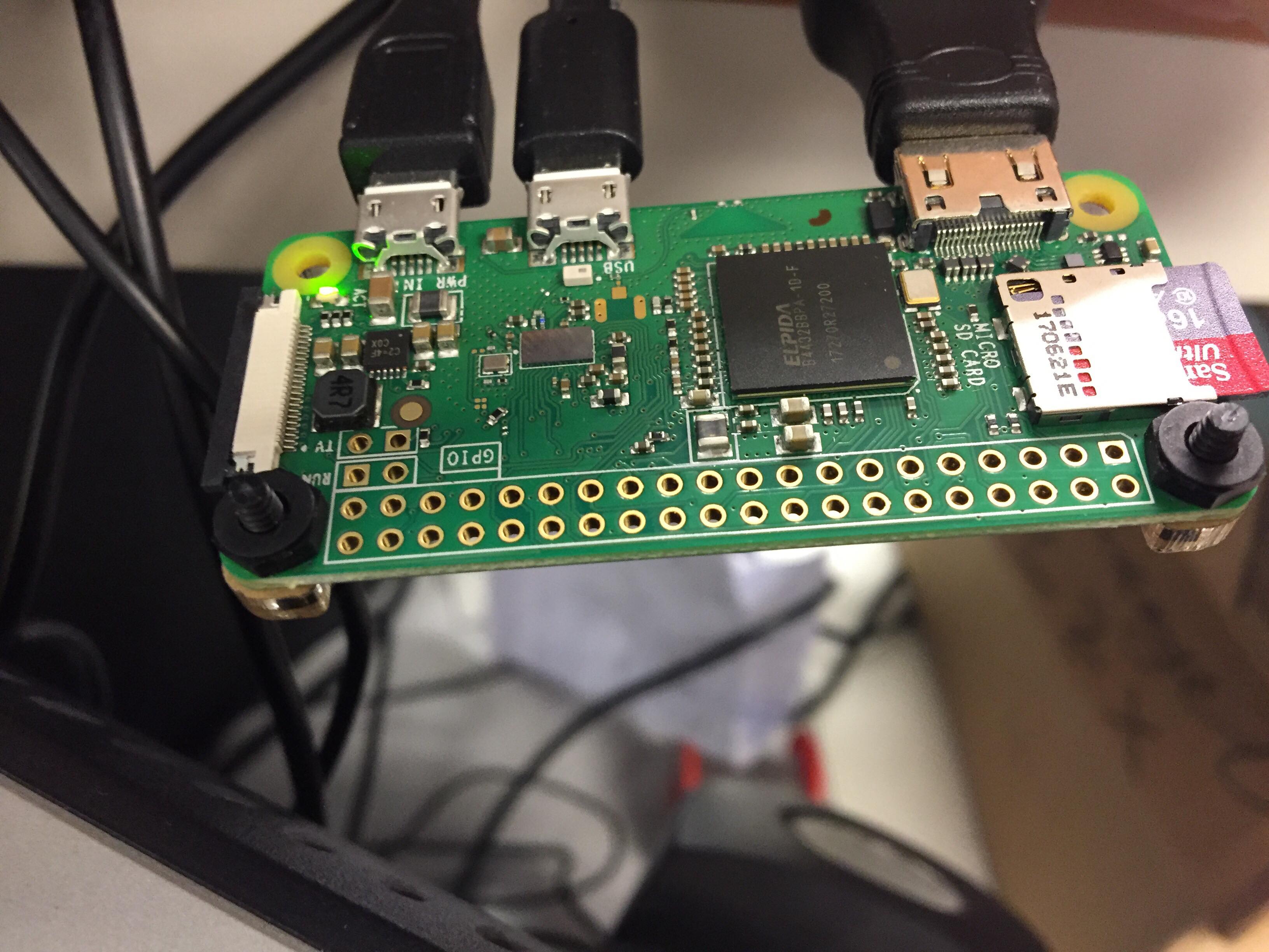
Figure 9. Raspberry Pi Zero was connected with the PiCamera and ran OpenCV algorithms.
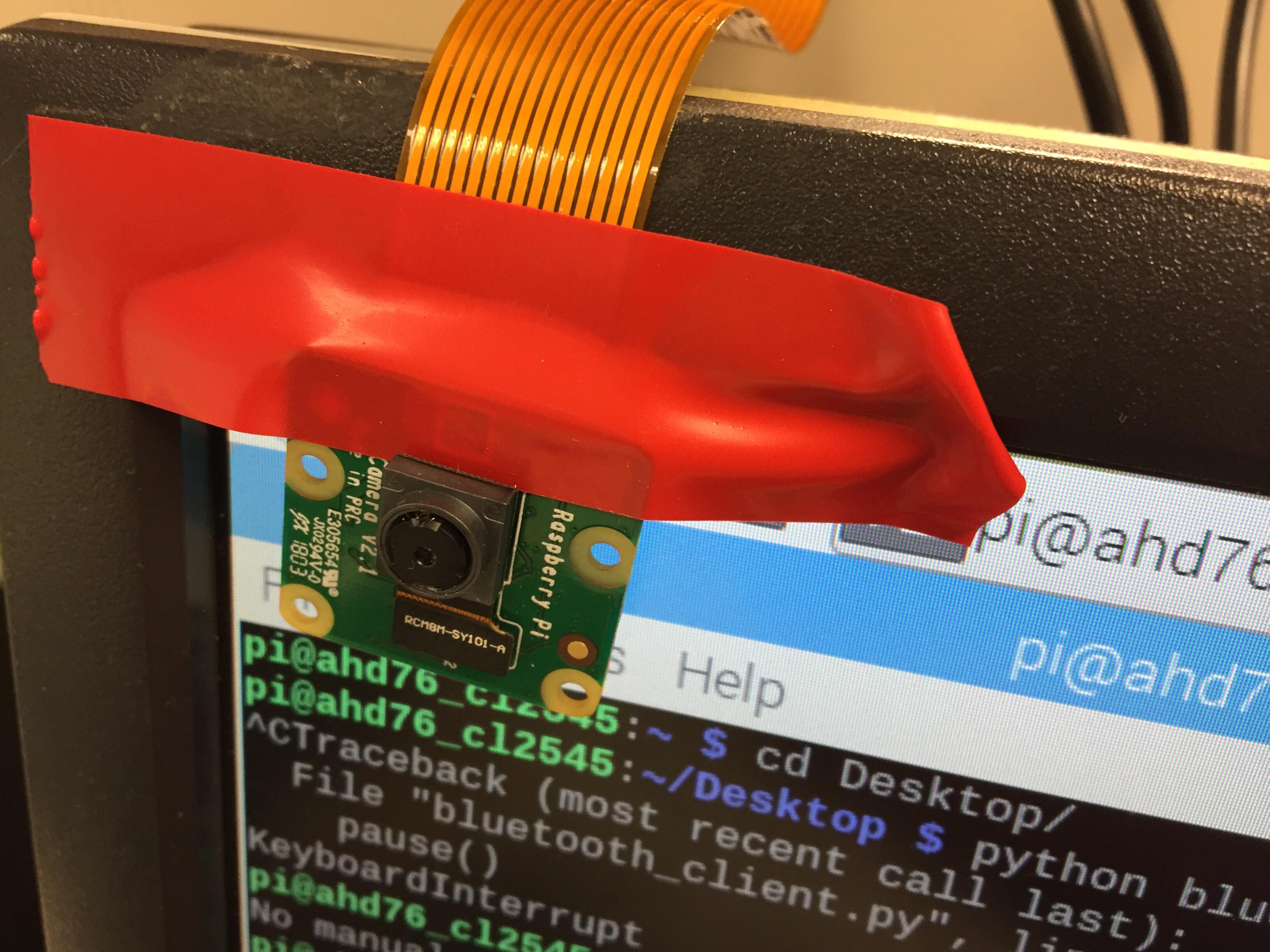
Figure 10. We used PiCamera to capture the frames.
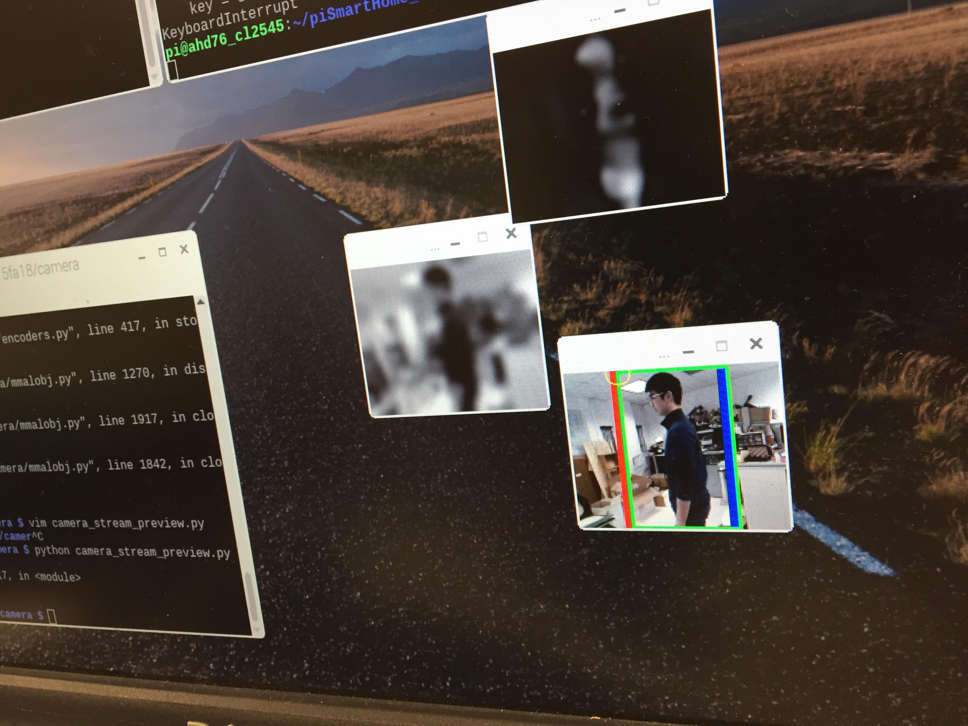
Figure 11. An object was detected and shown in the OpenCV window.
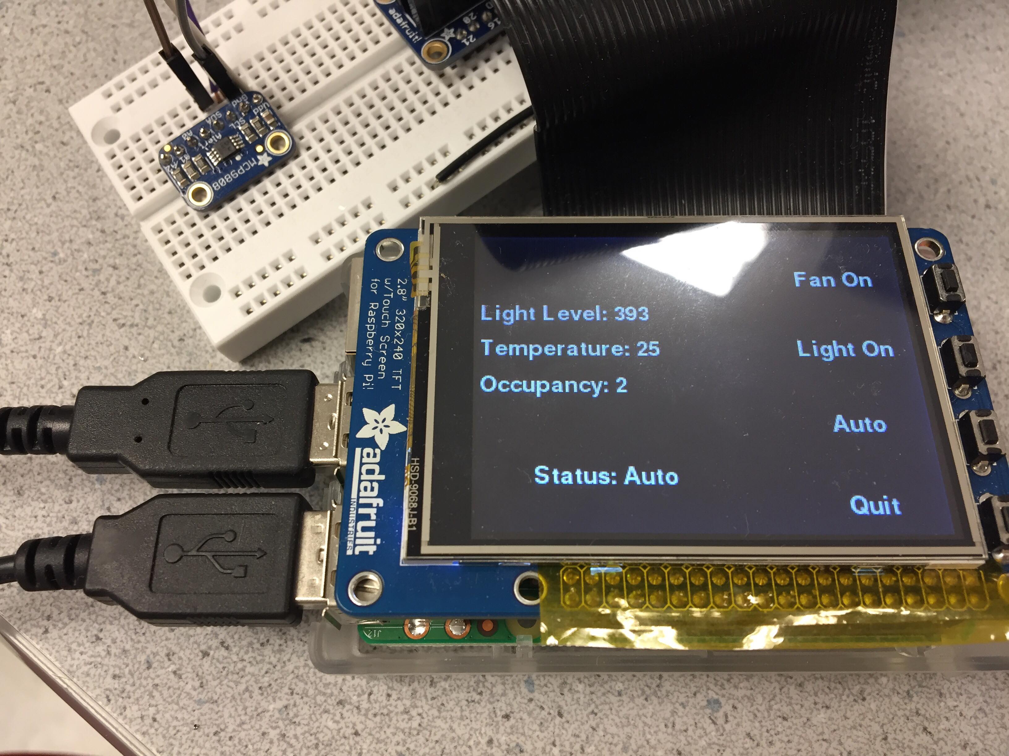
Figure 12. We built a minimalist UI on the TFT screen.
Results
As we had a well-defined timeline and plan at the beginning of the project, we were able to make good progress along our way. The main functionality of our system was executed with respect to the original plan, but due to the limited time we decided to eliminate supports for voice command and accesses via bluetooth on a smartphone. At the end, we were able to achieve a rather functional smart home system that conserved energy consumption according to the occupancy status in a room. Although occupancy tracking was sometimes glitchy, it was accurate for the majority of the time and we felt that it served as a good baseline for future expansion.
Conclusion
Our smart home system was able to automatically control the light and the fan installed in the system, and tracked the occupancy status in a room. The light would be on when the ambient light level was lower than 200 (lux value) and the fan would be on when the room temperature was higher than 26 degrees Celsius. The user had the power to override the automatic control and put the system into the manual mode, where the light and the fan can be controlled via GPIO buttons. In addition to the features described above, the system automatically resumed to auto mode when it detected that the last person left the room and the occupancy became 0. Among the implemented features in our smart home system, we thought that our algorithm could have worked better to track the movement across the doorway (enter/leave). One big problem we discovered during our demo was that if a person was wearing clothes that had a similar to the background color, then OpenCV would have a hard time picking the movement up since it was carrying out background subtraction. We were also dealing with the system randomly increasing or decreasing the occupancy at random times. The cause of these issues remained largely unknown but were believed to have their roots in the jittering object tracking and bluetooth communication. However, due to the limited amount of time, we were not able to take a further step and examine the exact causes of such issues.
Future Work
Several parts of the project could be expanded upon given more time. The major areas of improvement include the computer vision algorithms and the user interface. Additional features could also be added. These features include voice activated commands and connectivity to a smartphone device. Lastly, the perception of the environment could be expanded upon by increasing the breadth and type of the sensors and attaching additional devices that the system could control.
The first area of improvement could occur with better computer vision algorithms. The current algorithm only tracks a single person as they cross a doorway. Additional improvements could attempt to recognize a human head and allow for multiple people to cross the doorway simultaneously. Additionally, further software filtering would allow for cleaner camera inferences to better track motion. Motion is tracked by looking at a single point and checking if it passes a threshold, but a potential improvement could be to take an average over multiple points.
The second area of improvement is to augment the user interface. Currently, it consists of several button inputs for the user and displays current system information on the TFT screen. Additional design improvements could add color-coding to the display and enable touch screen communication with the TFT.
An additional feature that could be added is voice recognition to enable voice commands. To enable a single user’s voice to be recognized, a potentially simple cross correlation method may suffice, but to allow many users’ voices to be recognized, more sophisticated techniques may be necessary. One such idea is to use an RNN (recurrent neural network) for audio sequence classification.
Another feature that would enable greater connectivity of the system is to set up communication between the smart home system’s Raspberry Pi 3 and a smartphone. This would enable the system to be controlled remotely from a smartphone. This would require setting up wifi communication between the Raspberry Pi 3 and the smartphone.
Lastly, the system could be expanded by attaching more sensors to gain a better understanding of the environment and adding additional devices that the system could control. For example, we could add a heating device of the temperature were to drop below a certain level and additional sensors such as a humidity sensor.
Work Distribution
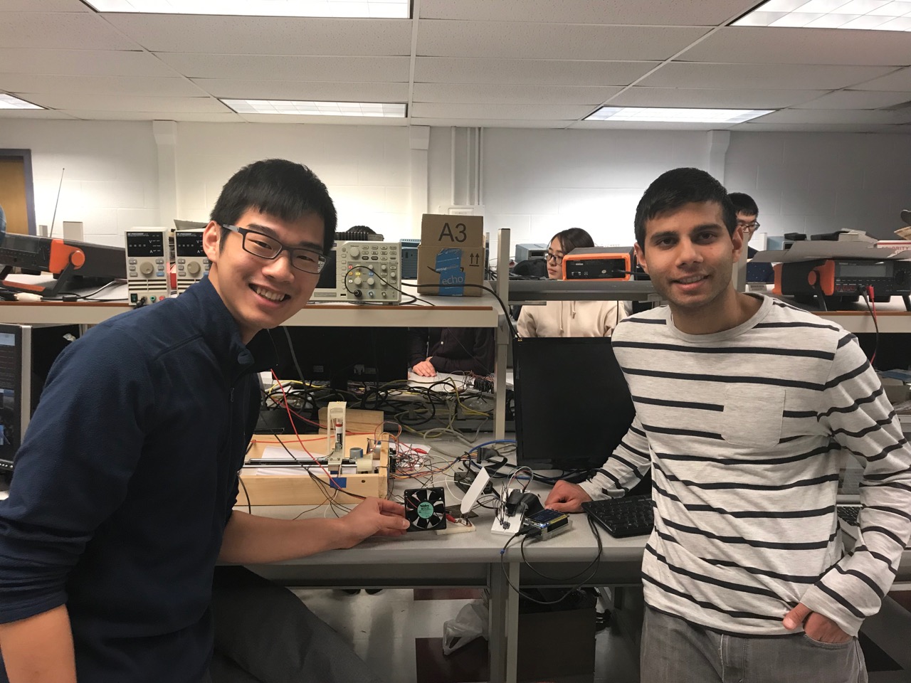
Project group picture

Anant Desai
ahd76@cornell.edu
Designed algorithms to integrate different sensors and device controls; set up bluetooth communication between raspberry pi 0 and raspberry pi 3; debugged occupancy counting openCV algorithm; obtained raspberry pi 0, USB hub, and PiCamera from prof/TAs; experimented with transistors to create current drivers for LED and fan; worked with hardware parts; worked with PiTFT user interface to display system stats and control system components for manual mode

Rick Lin
cl2545@cornell.edu
Installed and did initial testing with openCV; Designed algorithms to detect occupancy in a room; debugged occupancy counting openCV algorithm; ordered relevant light/temperature sensor and LED from adafruit; applied circuitry cleanly on the breadboard; worked with hardware parts; worked with PiTFT user interface to display system stats and control system components for auto mode
Parts List
- Raspberry Pi $39.95
- Raspberry Pi Zero $10.00
- Raspberry Pi Camera $29.95
- Mini Fan $7.00
- MCP 9808 Temperature Sensor $4.95
- TSL 2561 Light Sensor $5.95
- Transistors Provided in Lab
- LED Panel $2.50
Total: $100.30
Code Appendix
#!/usr/bin/python

##################################
# Pi Smart Home
##################################

# ECE 5725: Embedded OS (Fall 2018) @ Cornell University
# Authors : Anant Desai (ahd76), Rick Lin (cl2545)
# File    : basicCV_process.py
#
# This script utilized openCV to detect moving
# objects and inform the host of any changes in
# room occupancy

# Import necessary python libraries

from picamera.array import PiRGBArray
from picamera import PiCamera
from bluedot.btcomm import BluetoothClient
from signal import pause
import datetime
import time
import cv2
import imutils

# bluetooth communication sink
def data_received(data):
    pass

client = BluetoothClient('B8:27:EB:9A:90:25', data_received)

# initialize camera parameters
camera = PiCamera()
camera.vflip = True
#camera.hflip = True
frameWidth = 160
frameHeight = 128
leftBound = frameWidth / 4
rightBound = frameWidth - leftBound
contourSize = (frameWidth/10) * (frameHeight/10)
camera.resolution = (frameWidth, frameHeight)
rawCapture = PiRGBArray(camera, size=(frameWidth, frameHeight))
camera.capture(rawCapture, format='bgr')

# capture the reference frame
first = rawCapture.array
first = cv2.cvtColor(first, cv2.COLOR_BGR2GRAY)
first = cv2.GaussianBlur(first, (21, 21), 0)
lastX = -1
lastTime = datetime.datetime.now()
occupancy = 0

# capture the frames from videostream
camera.framerate = 15
rawCapture = PiRGBArray(camera, size=(frameWidth,frameHeight))

time.sleep(0.1)

for frame in camera.capture_continuous(rawCapture, format='bgr', use_video_port=True):
    # process the image using openCV functions
    image = frame.array
    gray = cv2.cvtColor(image, cv2.COLOR_BGR2GRAY)
    gray = cv2.GaussianBlur(gray, (21, 21), 0)
    frameDelta = cv2.absdiff(first, gray)
    thresh = cv2.threshold(frameDelta, 50, 255, cv2.THRESH_BINARY)[1]
    thresh = cv2.dilate(thresh, None, iterations=20)
    # find the object
    cnts = cv2.findContours(thresh.copy(),
            cv2.RETR_EXTERNAL,
            cv2.CHAIN_APPROX_SIMPLE)
    cnts = cnts[0] if imutils.is_cv2() else cnts[1]

    # draw left & right thresholds
    cv2.line(image, (rightBound, 0), (rightBound, frameHeight), (255,0,0), thickness=5)
    cv2.line(image, (leftBound, 0), (leftBound, frameHeight), (0,0,255), thickness=5)
    cnts2 = []
    for c in cnts:
        # drop the object if it's too small
        if cv2.contourArea(c) < contourSize:
            continue
        else:
            cnts2.append(c)

        (x, y, w, h) = cv2.boundingRect(c)
        if x < leftBound - 10 or x > rightBound + 10:
            cnts2.pop()
        else:
            cv2.rectangle(image, (x,y), (x+w, y+h), (0, 255, 0), 2)

    # if there is a object in the frame
    if len(cnts2) > 0:
        now = datetime.datetime.now()

        currX = cv2.boundingRect(cnts2[0])[0]
        currY = cv2.boundingRect(cnts2[0])[1]
        cv2.circle(image, (currX, currY), 10, (0, 255, 255))
        if lastX > 0 and (now - lastTime).total_seconds() > 1:
            if (currX - lastX) > 0 and currX > rightBound:
                # moving right -- send signal 0 to decrement occupancy
                client.send(str(0))
                occupancy -= 1
                lastX = -1
                lastTime = now
            elif (currX - lastX) < 0 and currX < leftBound:
                # moving left -- send signal 1 to increment occupancy
                client.send(str(1))
                occupancy += 1
                lastX = -1
                lastTime = now
            else:
                lastX = currX
        else:
            lastX = currX

    # also visualize the processing steps on screen
    cv2.imshow("Gray", gray)
    cv2.imshow("Delta", frameDelta)
    cv2.imshow("Image", image)
    key = cv2.waitKey(1) & 0xFF

    rawCapture.truncate(0)

    if key == ord("q"):
        break

cv2.destroyAllWindows()
#!/usr/bin/python

##################################
# Pi Smart Home
##################################

# ECE 5725: Embedded OS (Fall 2018) @ Cornell University
# Authors : Anant Desai (ahd76), Rick Lin (cl2545)
# File    : sensorControlledDevices.py
#
# This script controls the LED light panel and
# the radiator fan when the sensor readings reach
# the preset threholds.

# Import necessary python libraries
import RPi.GPIO as GPIO
from pygame.locals import *
import sys, pygame, os
from threading import Timer
import Adafruit_MCP9808.MCP9808 as MCP9808  # temperature sensor MCP9808
from tsl2561 import TSL2561                 # light sensor TSL2561
import time
from bluedot.btcomm import BluetoothServer
from signal import pause


# Set up the light/lux sensor (on I2C bus)
print '[SYSTEM] Initializing the light sensor'
lux = TSL2561(debug=True)
print '[SYSTEM] Ambient lux: ' + str(lux.lux())

# Set up the temperature sensor (a wrapper class from Adafruit)
print '[SYSTEM] Initializing the temperture sensor'
thermo = MCP9808.MCP9808()
thermo.begin()
print '[SYSTEM] Ambient temperature: ' + str(thermo.readTempC())

# Initialize the device switches to be OFF
print '[SYSTEM] Turn off the light and fan at the beginning'
fanOn = False
ledOn = False
auto = True

# set up TFT
flag = True
os.putenv('SDL_VIDEODRIVER', 'fbcon') # Display on piTFT
os.putenv('SDL_FBDEV', '/dev/fb1') #
os.putenv('SDL_MOUSEDRV', 'TSLIB') # Track mouse clicks on piTFT
os.putenv('SDL_MOUSEDEV', '/dev/input/touchscreen')
pygame.init()

# python code for suppressing mouse cursor
pygame.mouse.set_visible(False)

# dimensions of the screen
size = width, height = 320, 240
white = 255, 255, 255
black = 0, 0, 0
screen = pygame.display.set_mode(size)

# specify font for quit button
my_font = pygame.font.Font(None, 25)

# clear screen
screen.fill(black)


# set up bluetooth server
occupancy = 0 # initialize occpancy of room to 0

# bluetooth communication sink
def data_received(data):
    global occupancy
    if data[0] == '0':
        occupancy -= 1
    elif data[0] == '1':
        occupancy += 1
    if occupancy < 0:
        occupancy = 0
c = BluetoothServer(data_received)


# Set up GPIOs
print '[SYSTEM] Initializing GPIOs'
GPIO.setwarnings(False)
GPIO.setmode(GPIO.BCM)                      # use broadcom numbering
GPIO.setup([5, 6], GPIO.OUT)                # device transistor output pins
TFT_buttons = [17, 22, 23, 27]
GPIO.setup(TFT_buttons, GPIO.IN, pull_up_down=GPIO.PUD_UP)

# setup button callbacks
def GPIO17_callback(channel):
    global auto
    global fanOn
    fanOn = not fanOn
    auto = False
GPIO.add_event_detect(17, GPIO.FALLING, callback=GPIO17_callback, bouncetime=300)

def GPIO22_callback(channel):
    global auto
    global ledOn
    ledOn = not ledOn
    auto = False
GPIO.add_event_detect(22, GPIO.FALLING, callback=GPIO22_callback, bouncetime=300)

def GPIO23_callback(channel):
    global auto
    auto = True
GPIO.add_event_detect(23, GPIO.FALLING, callback=GPIO23_callback, bouncetime=300)

def GPIO27_callback(channel):
    global flag
    flag = False
GPIO.add_event_detect(27, GPIO.FALLING, callback=GPIO27_callback, bouncetime=300)

# main loop
while flag:

    # read sensor values
    luxValue = lux.lux()
    tempValue = thermo.readTempC()

    fan_str = "On"
    if fanOn:
        fan_str = "Off"

    led_str = "On"
    if ledOn:
        led_str = "Off"

    status_str = "Manual"
    if auto:
        status_str = "Auto"

    # draw control buttons
    screen.fill(black)
    text_surface1 = my_font.render('Fan ' + fan_str, True, white)
    rect1 = text_surface1.get_rect(center=(width-50,height-200))
    screen.blit(text_surface1, rect1)
    text_surface2 = my_font.render('Light ' + led_str, True, white)
    rect2 = text_surface2.get_rect(center=(width-50,height-140))
    screen.blit(text_surface2, rect2)
    text_surface3 = my_font.render('Auto', True, white)
    rect3 = text_surface3.get_rect(center=(width-50,height-80))
    screen.blit(text_surface3, rect3)
    text_surface4 = my_font.render('Quit', True, white)
    rect4 = text_surface4.get_rect(center=(width-50,height-20))
    screen.blit(text_surface4, rect4)
    text_lux = my_font.render('Light Level: ' + str(luxValue), True, white)
    text_lux_rect = text_surface1.get_rect(center=(30,70))
    screen.blit(text_lux, text_lux_rect)
    text_temp = my_font.render('Temperature: ' + str(int(tempValue)), True, white)
    text_temp_rect = text_surface1.get_rect(center=(30, 100))
    screen.blit(text_temp, text_temp_rect)
    text_occu = my_font.render('Occupancy: ' + str(occupancy), True, white)
    text_occu_rect = text_surface1.get_rect(center=(30, 130))
    screen.blit(text_occu, text_occu_rect)

    text_sys = my_font.render('Status: ' + status_str, True, white)
    text_sys_rect = text_sys.get_rect(center=(90, 200))
    screen.blit(text_sys, text_sys_rect)

    pygame.display.flip()

    # control the devices according to sensor values
    if occupancy == 0:
        auto = True

    if auto and luxValue < 200 and occupancy > 0:
        ledOn = True
    elif auto:
        ledOn = False

    if auto and tempValue > 26 and occupancy > 0:
        fanOn = True
    elif auto:
        fanOn = False

    # write outputs to GPIOs
    GPIO.output(5, fanOn)
    GPIO.output(6, ledOn)
    time.sleep(0.5)

print ''
print '[SYSTEM] Terminating the controls'
print '[SYSTEM] Cleaning up the GPIOs'
GPIO.cleanup()