Power saving system for Home Automation

Figure 1: Hardware Setup
Introduction
This project falls under the domain of Home Automation which further falls under the category of Internet of Things (IoT). Home automation might not be new, but a recent boom in smart home technology has thrust it straight into the spotlight with companies like Google, Amazon and Lutron pushing it to the next level. Market experts predict that smart home markets share will be worth tens of billions within the next few years. Our project is about saving power by sensing the presence of an individual in the room. People often leave their homes in a rush and forget to turn off home appliances like fans and lights to name a few. Our design senses the presence or absence of a person and will turn appliances of the room On or Off. The design comprises of Raspberry Pi as the central unit.We have decided to design a ‘Node’ that will comprise of Raspberry Pi 0W and a Passive Infrared (PIR) Sensor.
For a given room, there will be at least 2-3 nodes present. The nodes communicate with each other and with the Raspberry Pi through Wireless-Fidelity(Wi-Fi). The nodes will detect absence or presence of an individual in the area and send an appropriate signal to the Raspberry Pi 3B also known as the hub. The hub is connected to the AC appliances like lights and fans through a multi-channel relay circuit. If presence isdetected, the nodes will send a signal to the hub which will trigger the relay to turn on the Appliance. Similarly, if the appliance if on without the presence of an individual, the node will send a signal to the hub which will trigger the relay to turn off the appliance thereby saving power. The next part of the project is to display the position of the individual on the piTFT. We will a prediction algorithm that will predict the motion of an individual in the room. The position information will be transmitted by the nodes to the hub

Figure 2: 110v Power Socket with PIR sensors
Project Objectives
Preferred Deliverables
-
Prediction about human moment in dead zones.
-
Detect new PIR sensor additions (Auto Enrol).
-
Detect dead PIR sensor nodes (Auto Death).
Minimum Deliverables
-
Read Data from PIR Sensor.
-
Multiple PIR Sensor integration with message queues and sockets.
-
piTFT room layout display
Design
This project is a fusion of hardware and software. On the hardware end, we will be usingRaspberry Pi 3B as the core component. Along with the Pi, we will be using PIR sensors,1 or 2 channel relay switch, Raspberry Pi 0W and the piTFT 2.8” Resistive TouchscreenDisplay. Each node comprises of one Raspberry-Pi 0W and a PIR sensor. The central hub is the Raspberry-Pi 3B. Appliances are controlled by the hub using a multi-channel relay switch. The nodes will communicate with each other and the hub through Wi-Fi. The hub is equipped with a 2.8” Resistive piTFT for displaying motion using prediction analysis.On the software end, we will be using python to write scripts to the Pi and we will use pyGame to display motion. Motion will be displayed on the 2.8” TFT. The Hub and nodes will be powered by battery cells. Nodes by coin cells and Hub by a battery pack.
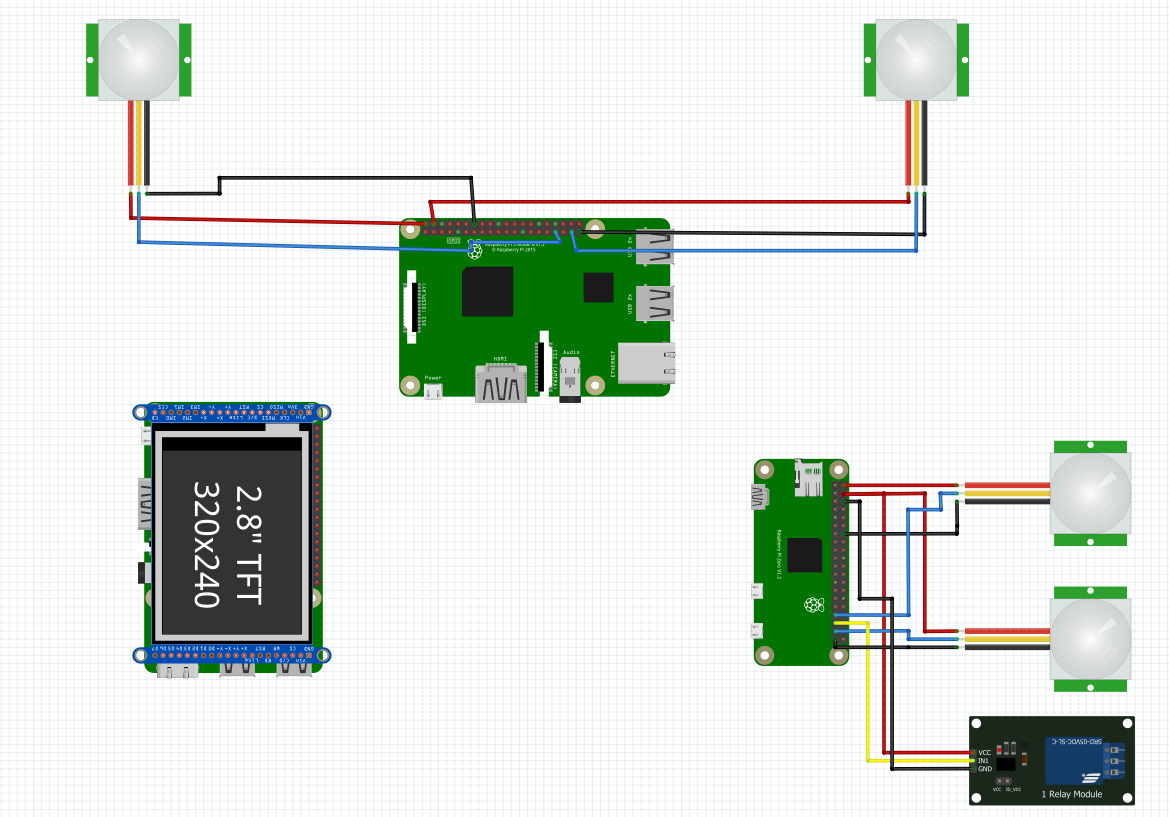
Figure 3: Design & Architecture
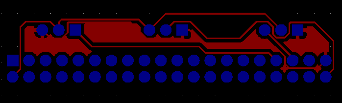
Figure 3: PCB design
Project as an Embedded System
We will using Raspberry PI 3B as an independent embedded controller with the piTFT.We will display the motion heat map on the piTFT. It also connects to the relays which run the various IOT appliances. We also plan to make a plug and play Rasbperry Pi Zero and relay IOT node for normal electrical appliances. We will be running sockets across the various Pi Zeros to communicate the sensor data.

Figure 4: Heat Map
Software Design
Nodes are developed to be independent processes. The hub and nodes are designed to be detached systems. They function without the presence of the other. We achieve this through a distributed multi-threaded system which communicated via sockets which are interface between the application and network layer. The hub runs a heatmap on the main thread which detects the PIR sensors and presence of humans in the lab. We have separate threads for each of the nodes which executes the receiver protocol. These threads update shared variables which are picked up by the main thread and displayed on the piTFT. If for some reason the node fails, the hub automatically detects the dead socket and updates the piTFT. Also, the same works for auto enrol. The threads scan through the sockets to acknowledge any new node connections. The nodes sent their location and PIR sensor data to the hub in JSON format.Testing
PIR Testing
We tested the Passive Infrared Sensor (PIR) on the Raspberry Pi 3B. A PIR has three terminals i.e. +Vcc, SIG and GND. +Vcc was connected to Pin 2 of the Raspberry Pi. GND was connected to Pin 39 and the SIG terminal was connected to GPIO 26. A PIR sensor will output ‘1’ if it detects presence in its proximity. We wrote a Python script where, GPIO 26 was setup as an input pin. In a ‘while True’ loop, we checked the signal at GPIO 26 every 5 seconds. If the PIR was OFF, it would not input any signal to the GPIO. If it detected presence, it would input ‘1’ or ‘HIGH’ to GPIO 26. We carried this test for four PIR sensors and each sensor behaved as expected.Relay Testing
We tested a single channel relay on the Raspberry Pi 3B. The single channel relay has three terminals i.e. +Vcc, SIG and GND. +Vcc was connected to Pin 3 of the Raspberry Pi. GND was connected to Pin 39 and the SIG terminal was connected to GPIO 19. The relay was configured to be an output device which means that, the Raspberry Pi will drive the relay instead of taking any signal from the relay as in the case of the PIR sensor.-
Tick Test: This was the very first test we performed for the relay. The SIG pin of the relay was toggled between ‘1’ and ‘0’ or ‘HIGH’ and ‘LOW’. Whenever the relay is in the ‘OFF’ state, there is a connection between ‘Common’ and ‘Normally Closed’. This is the default connection of the relay. Thus, there is no tick heard. Once the GPIO toggles from ‘0’ to ‘1’, the relay switches from ‘Normally Closed’ to ‘Normally Open’. Hence there is a tick sound heard. Now there is a connection between ‘Common’ and ‘Normally Open’. If the GPIO toggles from ‘1’ to ‘0’, the relay switches back to its default ‘Normally Closed’ state and once again a tick is heard. This test was repeated 110 times to check the performance of the relay.
-
Multimeter Test: The multimeter test was performed on the relay by connecting a multimeter between ‘Common’ and ‘Normally Open’. The configuration of the relay and the connections were kept same as in the tick test. The multimeter mode was set as ‘Connectivity Mode’ where the multimeter beeps if there is connection. Whenever the GPIO toggled and the relay changed its state, the multimeter was beeping due to a connection between ‘Common’ and ‘Normally Open’. This test was repeated 40 time to check the performance of the relay.
-
Fan Test: In this test we wanted to check the performance of the relay with a load. The relay configuration was the same as in the previous two tests. The load used was a 5-9V DC fan. We used an external power supply to power on the fan. The positive terminal of the external power supply was connected to the ‘Common Terminal’. One terminal of the fan was connected to the ‘Normally Open’ terminal and the other terminal of the fan was connected to the negative terminal of the external power supply. The supply was then turned on. Due to the default state of the relay, the fan did not rotate due to no connection between ‘NO’ and ‘Common’. When the GPIO toggled from ‘0’ to ‘1’, there was a connection between ‘Common’ and ‘NO’ and the fan was working as expected.
Demo
The node which comprised of Raspberry Pi 0W, PIR sensor and the single channel relay module was taken. We designed a silver electric box which was consisted of the Alternating Conditions (AC) connections. The ‘HOT LIVE’ was connected to the ‘Common’ terminal of the relay. The ‘Switched Live’ from the ‘Normally Open’ Terminal of the relay was connected to a lamp which consisted of a Bulb. The other terminal of the bulb was connected to the ‘Neutral’ wire. These connections were made over a socket. The socket, relay and the connections were enclosed in the electric box. We made sure that there are no open wires and the live wires are insulated with insulation tape for safety from electrical hazards. The ‘Ground’ wire was also connected to the socket. The three relay terminals i.e. +Vcc, SIG and GND were connected to the Raspberry Pi 0W. We used extended wires for this since the relay was enclosed in the electrical box and isolated from the RPi 0W. The PIR sensor on the node triggered the RPi to drive the relay and the relay then switched to supply ‘Hot Live’ to the lamp. For this node, we used two PIR sensors and two lamps since our socket had provision for connecting two lamps. By doing this we ensued that one workstation can be automated by using a single node. By connection multiple nodes, relay modules and sockets, we can also automate the neighboring work stations. The Hub comprised of the RPi 3B along with 2.8’’ TFT Resistive Touchscreen. The third Raspberry Pi was also a Raspberry Pi 3B and had two PIR sensors connected. The RPi was kept between two workstations and we used single-core wires to connect PIR sensors which were placed over two work stations. There is scope to automate different workstations by connecting the electrical box comprising of relay, sockets and lamps controlled by the node. This RPi was configured to auto-enrol. This means, when the Pi is booted, it will scan for the Wi-Fi to which the Hub and Nodes are connected and will automatically connect to the Wi-Fi and take part in the communication.Demo Video
Work Distribution
Chirag Wadhwani: Hardware design and wiring.Karthik Dasaraju: Software design and interfacing.
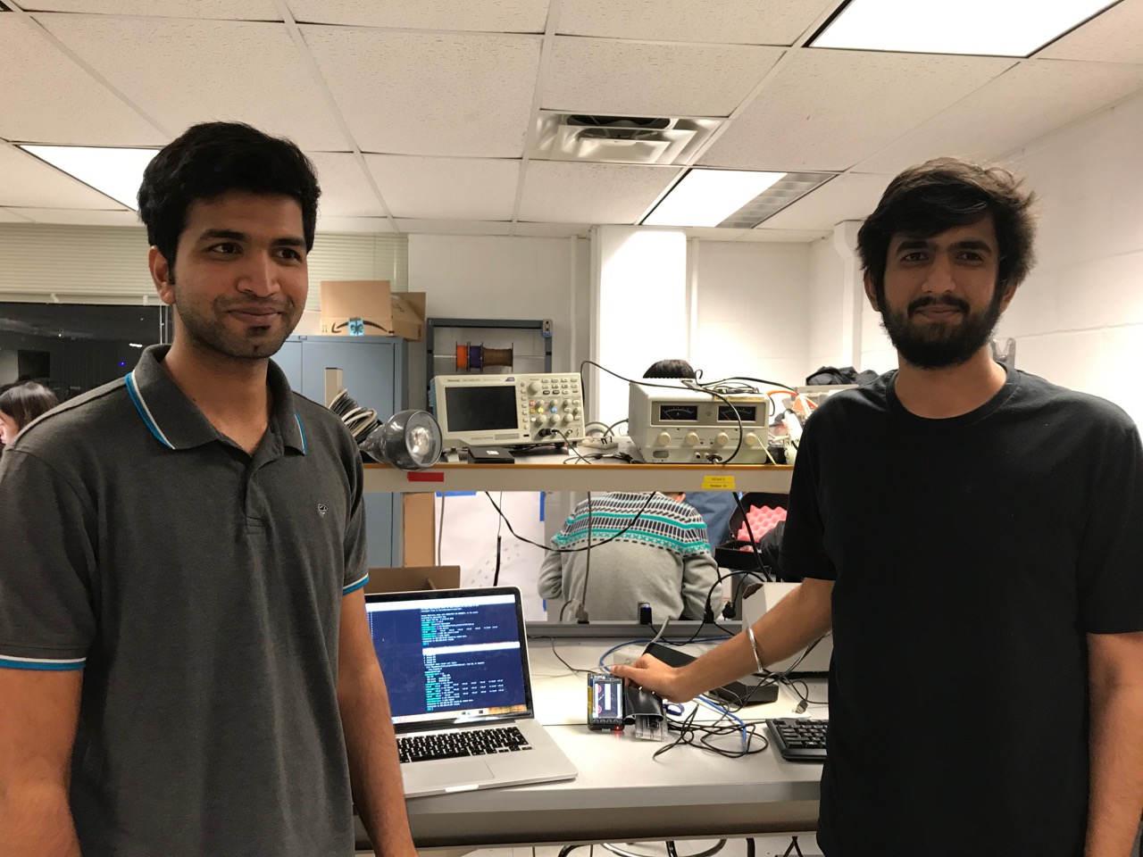
Karthik and Chirag (from left to right).
Parts
| Item Name | Quantity | Cost | Link |
|---|---|---|---|
| Raspberry Pi 3 Model B | 2 | $35 | https://www.adafruit.com/product/3055 |
| Raspberry Pi Zero W | 1 | $10 | https://www.adafruit.com/product/3400 |
| SunFounder Relay Module | 1 | $6 | http://a.co/d/3J4lTFp |
| PIR Sensors | 1 | $9 | http://a.co/d/6BwZYfk |
Conclusion
We successfully demonstrated our power saving system for home automation. We made a robust and a dynamic system capable of auto detecting new nodes and also death of existing nodes. We made an embedded system where the hub and nodes automatically inherit their roles on bootup. We also displayed the heatmap on the piTFT. We also controlled two 110v lambs via a relay which were triggered from a PIR sensor. We believe our system would save millions in energy bills by turning of unused appliances.References
-
Raspberry Pi: https://projects.raspberrypi.org/en/projects/raspberry-pi-getting-started
-
Python Sockets: https://realpython.com/python-sockets/
-
Python Multithreading: https://www.geeksforgeeks.org/multithreading-python-set-1/
-
PIR Sensor: https://cdn-learn.adafruit.com/downloads/pdf/pir-passive-infrared-proximity-motion-sensor.pdf