Raspberry Pi Arcade Station
The goal of this project was to construct a standalone table-top arcade station using the Raspberry Pi. Our inspiration for this project came from our mutual fondness for classic video games and interest in using the versatile capabilities of the Linux operating system on the Raspberry Pi. The arcade station features a pre-built kernel that runs an EmulationStation playing classic video games as well as our own custom-built Python games all housed within a custom-made laser-cut wooden cabinet.
Introduction
This project has extensive hardware and software aspects that were developed concurrently. On the hardware side, the entire cabinet needed to be designed, laser-cut, and assembled with the purchased arcade peripherals. All of the buttons and the joystick needed to have their leads crimped and soldered in order to cleanly interface with the GPIO pins of the Raspberry Pi. Finally, the 3.5mm jack needed to be broken out so that all four connection points were exposed and could be spliced into separate connectors to produce composite video for the screen as well as a stereo output for the speakers. On the software side, we created a menu screen that launches on bootup of the system. Within this menu screen, the user can launch a pre-built EmulationStation which can run emulators of classic systems like the Nintendo Game Boy, NES, SNES, and much more. Within these emulators, we pre-loaded a sampling of classic video game ROMs. The GPIO button inputs to the Raspberry Pi are mapped to a virtual gamepad which can be used to manipulate menu screens and perform actions within the custom-build games and ROMs. While working on top of this pre-built image, we made three of our own Python games. In the main menu of the system, one can read an ‘About’ section listing out the developer names, launch the pre-built EmulationStation to play classic game ROMs, play any of the three games we built, view the high scores for our pre-built games, and cleanly shut down the system.
Design and Testing
Hardware
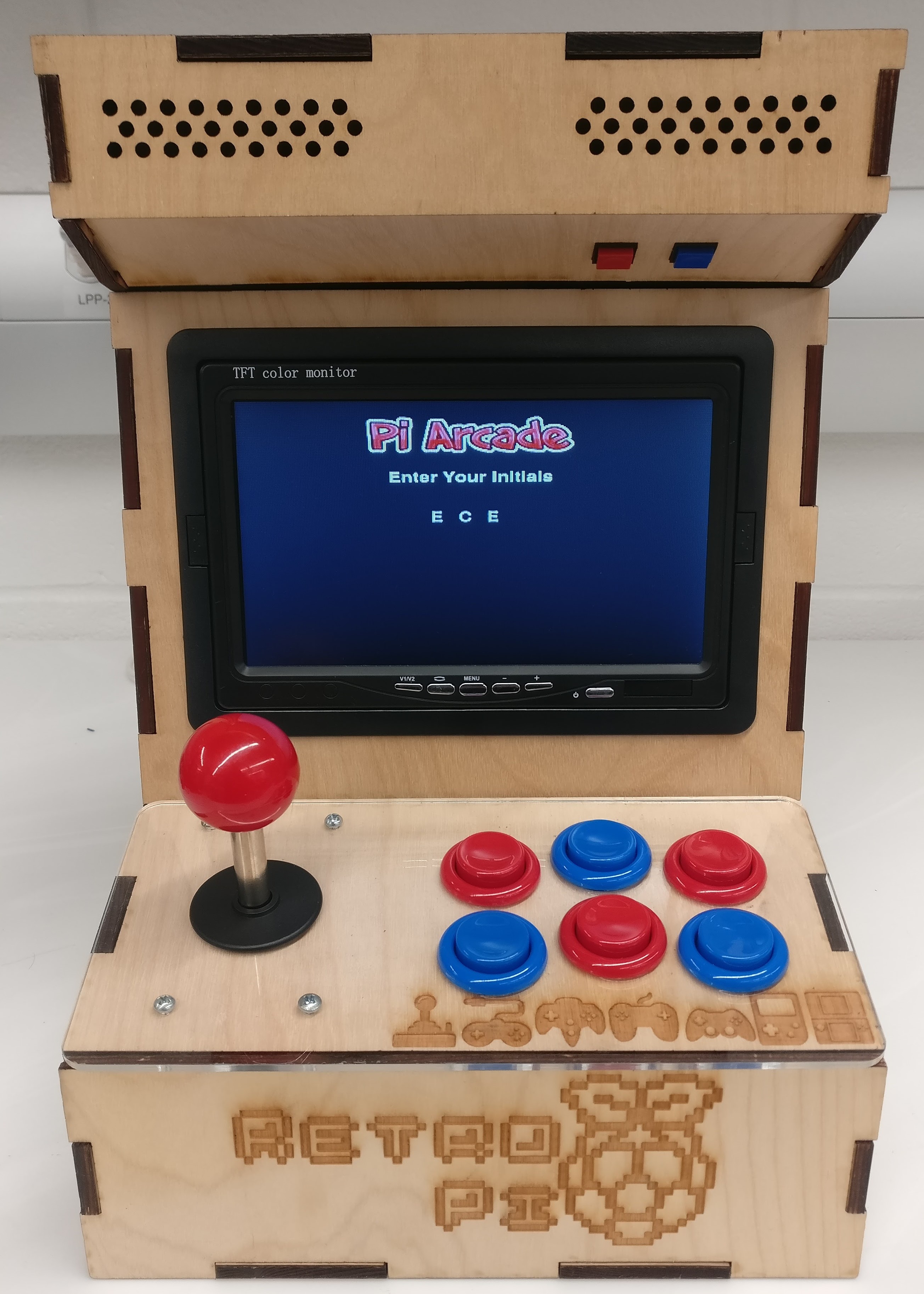
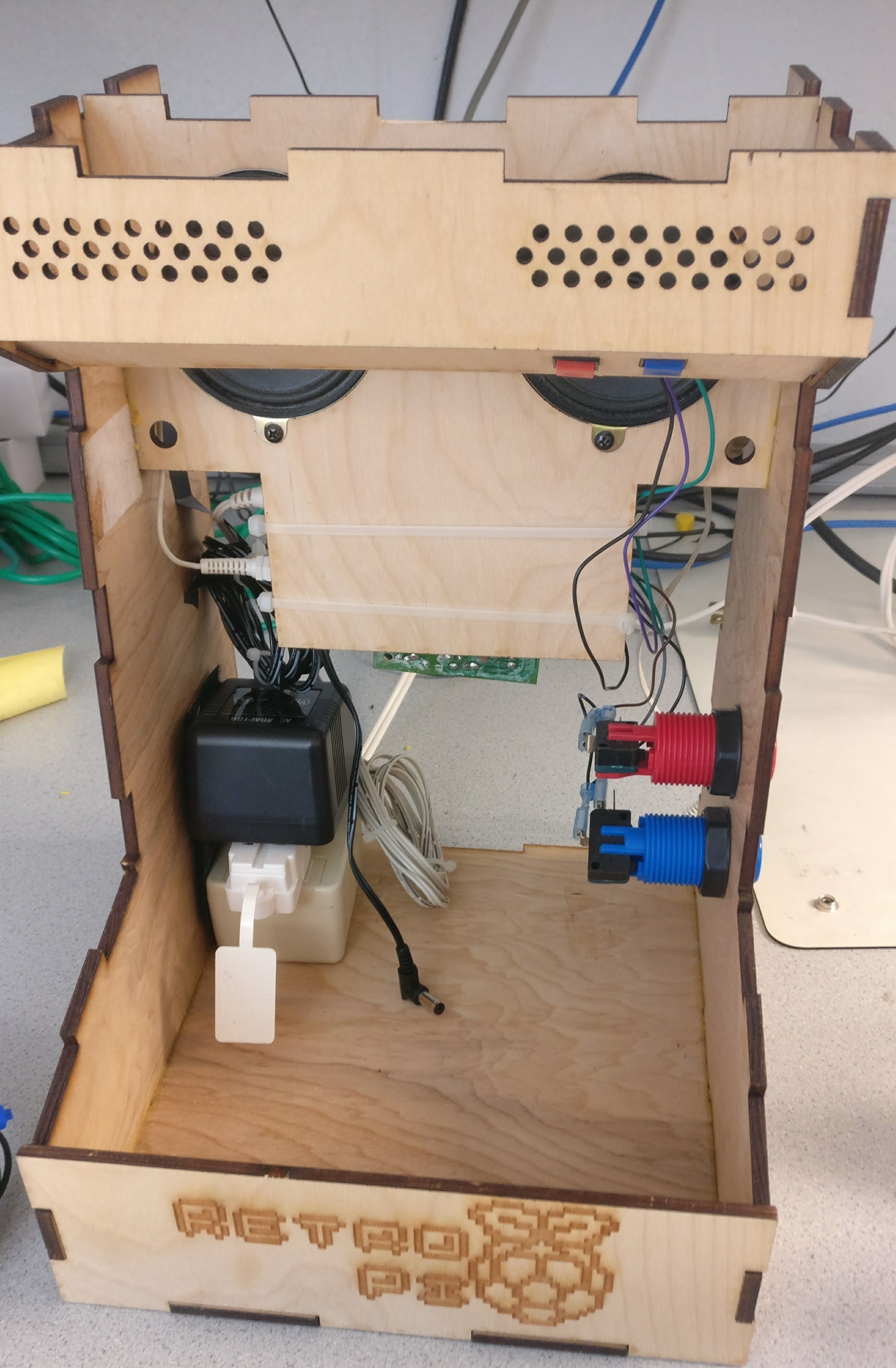
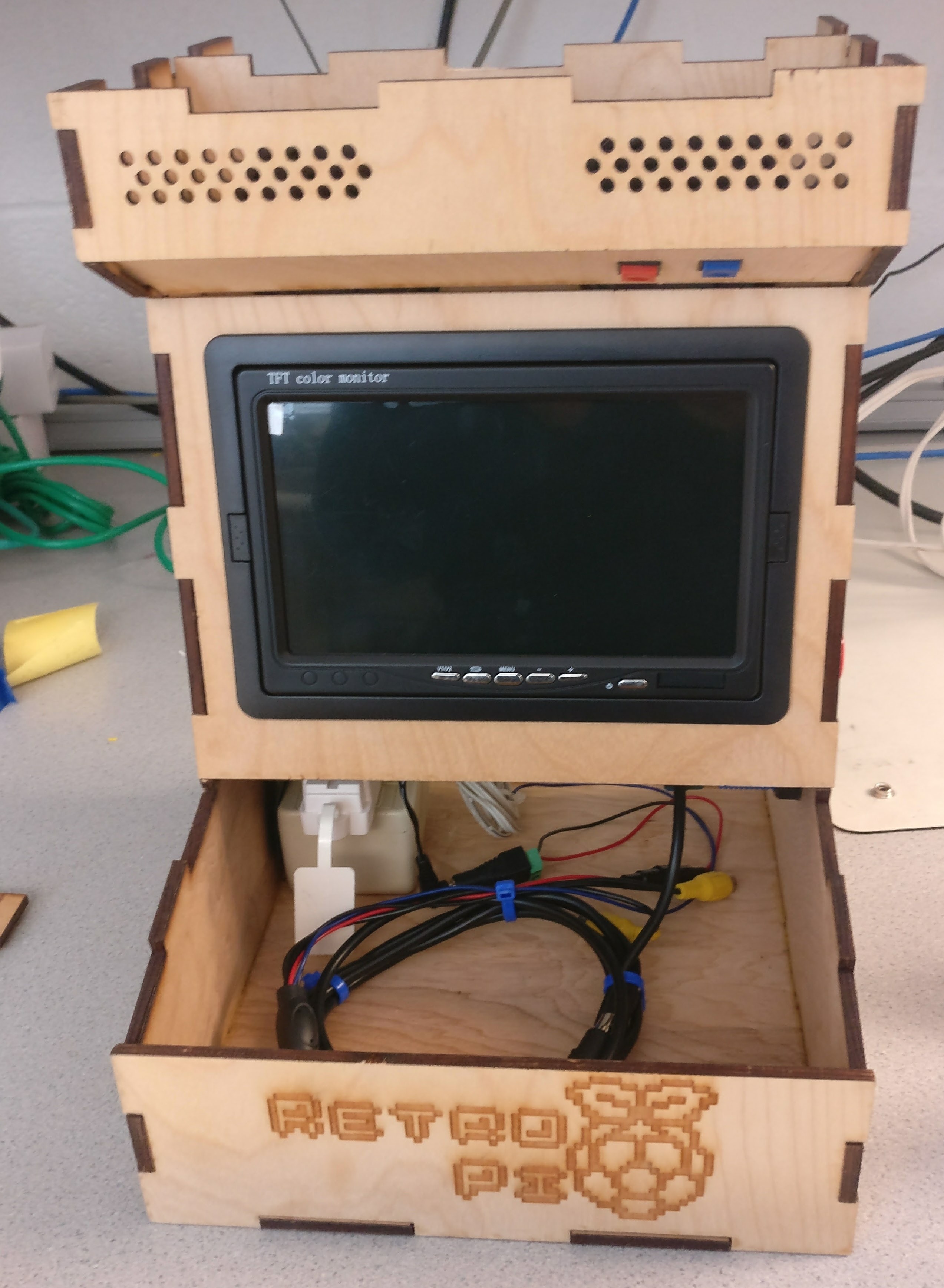
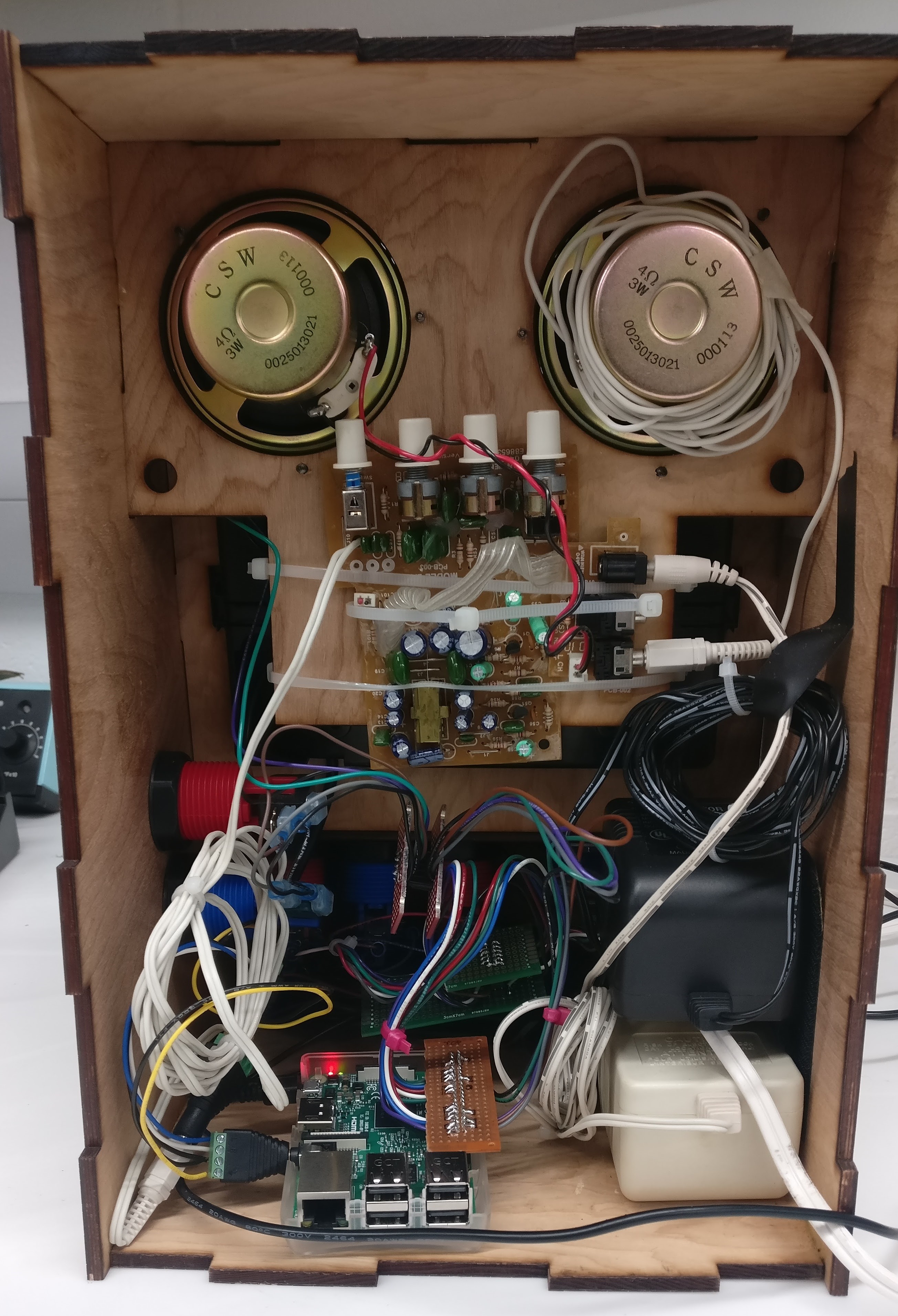
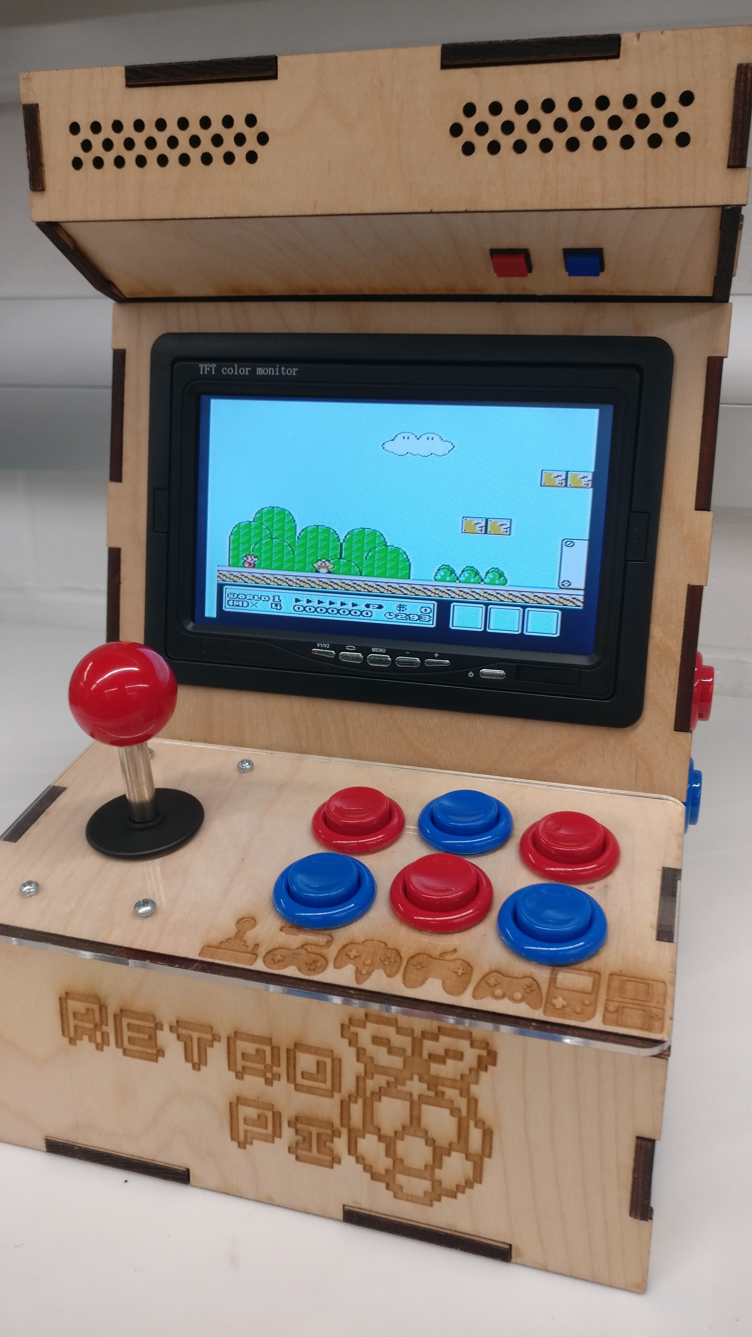
The hardware components of the system include the screen, joystick, buttons, speakers, the laser-cut frame, and the Raspberry Pi. The 7 inch screen intended for use within cars as a rear view camera. The joystick and buttons mimic those of classic arcade machines. The speakers are repurposed desktop speakers that have been stripped of their casing: only the electronics from the speakers have been included in the arcade station housing. The entire system is fully self-contained and doesn’t require any other peripherals to operate. It does, however, allow the user to plug in USB devices (i.e. keyboard and mouse), as well as access the micro-SD card.
All of the modeling for this project was done by us. Using the Autodesk Inventor suite, we constructed a 3D model and each face of the different arcade station housing were put into one template file to be created with a laser-cutter. Overall, we are satisfied with the sturdiness, durability, and general ergonomics of our final design, which we believe offers a comfortable and entertaining gameplay experience.
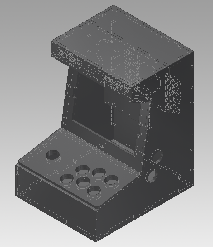
The assembly process for this housing was quite simple. The pieces were designed using finger joints, allowing for quick construction. Due to the accuracy of our laser-cutting, the frame pieced together effortlessly and no additional modifications to the quarter-inch plywood cuts were necessary. During the assembly process, we used wood glue to hold certain parts of the frame together, but others were left unfixed to allow for quick access of the internal electronics. The system was built in such a way that press-fitting pieces would hold the un-glued pieces together quite reliably. The front panel for buttons, the screen panel, the top of the arcade, and the back of the arcade are all capable of being removed if modification is necessary.
All of the buttons and joystick controls are mapped to GPIO input pins on the Raspberry Pi. Two small buttons hidden at the top of the system’s housing contain two pins each. The arcade style buttons have three pins designations: ground, active-low, and active-high. We used the active-low and ground pins so that pressing a button would drive the input pin to the Raspberry Pi low and trigger a falling-edge callback event within our Python program. Each button within the joystick featured the same pinout as the arcade buttons. The final mapping for the joystick and arcade button peripherals is shown below.
| Function | GPIO Pin (BCM Mapping) |
|---|---|
| Up | 10 |
| Down | 22 |
| Left | 27 |
| Right | 17 |
| Start | 16 |
| Select | 20 |
| A | 9 |
| B | 5 |
| X | 13 |
| Y | 26 |
| L | 6 |
| R | 4 |
| Debug #1 | 12 |
| Debug #2 | 23 |
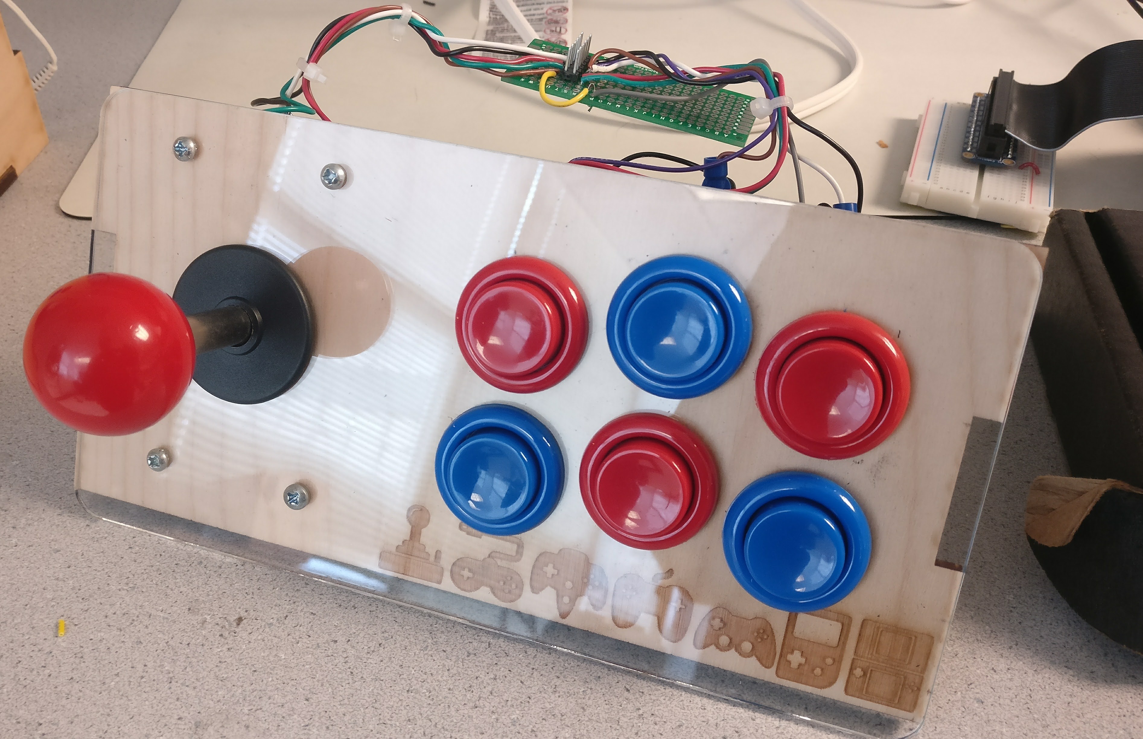
After a mapping was decided upon, connectors were soldered and crimped to connect the various peripherals to the Raspberry Pi. We set out to make the system as modular as possible to make the system easier to methodically debug. The joystick and main six arcade buttons on the front of the cabinet are soldered to a perf board with a header, the two side buttons and the two debug buttons at the top of the arcade are on a separate perf board with a header, and both of these headers interface with the Raspberry Pi through a breakout on a perf board.
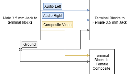
The Raspberry Pi PCB contains a 3.5mm jack. If a speaker cable is plugged into this port, the system immediately outputs audio given that the audio signals for stereo output are left, right, and ground. The 3.5mm jack is actually a four port jack that is capable of outputting an additional video signal. The video signal allows for composite video which is what our screen uses. The four pins from tip to sleeve are usually mapped as left audio, right audio, video signal, ground. However, on the Raspberry Pi, the mapping is left audio, right audio, ground, video signal. As a result, standard cables that breakout 3.5mm to stereo audio and video do not work because the ground is not properly shared. We used a host of adapters to split the 3.5mm jack into two separate connectors: one for audio and one for video. To properly output composite video the file /boot/config.txt was modified to uncomment the line containing “#sdtv_mode=0 and set sdtv_mode=2” which outputs composite video. With these modifications, if an HDMI peripheral is connected to the Raspberry Pi, then the video signal will output to HDMI. Otherwise, the Raspberry Pi will output composite video on the 3.5mm jack. In addition, within the /boot/config.txt file, we modified the overscan properties slightly in order to have the visuals go to the very edges of the display. This is something that requires a good deal of trial and error and is solely dependent of the unique screen hardware.
Software
Our entire project was developed on the most recent RetroPie image version 4.3 which is built to run on the Raspberry Pi 3B. Within this distribution, it’s possible to play classic ROMs using the program “EmulationStation”. Online, we were able to acquire some ROMs of classic video games with the correct file type for EmulationStation, as specified within the RetroPie documentation, which we then dropped into the appropriate folder within the file system. With the ROMs in the appropriate directory, running EmulationStation would display the games within the main game menu for play. When configuring the system, we made some user interface adjustments within the RetroPie menu screens to make the system more eye appealing. Our biggest challenge when configuring EmulationStation was configuration of our own button input interface, as we will discuss in the GPIONext section.
GPIONext is a daemon that runs in the background which facilitates the mapping of GPIO pins to a virtual “joypad”. This virtual joypad is the default source for game inputs within the EmulationStation program. When EmulationStation is first started, keyboards are automatically configured to work on all menus, but with additional configuration it’s possible to use other game controllers and external peripherals. Unlike our own Python PyGame programs, we can’t read in the GPIO pins and map them to functions because EmulationStation is a standalone program. Using the GPIONext daemon allows for mappings between custom external peripherals with the virtual joypad used by EmulationStation. The GPIONext daemon works by starting up on bootup and stopping on a safe shut down of the system. The daemon will essentially create a virtual joypad which the RetroPie EmulationStation software will treat as an input from a USB-controller. When configuring the daemon, it lets you select which types of buttons you want mapped: i.e. up, down, left, right, start, select, etc. Once all those buttons are mappings are selected, a menu pops up asking for you to hold a button to have it mapped to that joypad input. By launching EmulationStation, we were able to use the software’s internal configuration menu to map the detected virtual joypad created by the GPIOnext daemon to that of the EmulationStation’s button mappings for games and menu controls. While this daemon works for this system, it has its drawbacks. The daemon takes a very long time to safely close causing the system to have a very long shut down time. During the testing and use of this piece of software, we found that if the Python script crashes or exits to the command line terminal prompt and is relaunched, then the daemon will not work within EmulationStation. In this scenario, the user could input the daemons commands in a terminal window to restart the daemon, but in the case of an embedded system with no keyboard control, a safe restart of the entire system will reset the daemon into a working state. This is not an ideal solution, and we acknowledge that there might exist a better GPIO daemon that would make the system more robust overall.
In order for this system to be a fully embedded system, we wanted our menu screen to be launched upon boot up of the system. Our menu screen, all of our own games, software shut down, and launching EmulationStation are all coordinated by one Python program. We first tried to set up a command within rc.local of the Raspberry Pi to launch this program on bootup. The issue we faced was that the bootup was not always successful with launching our scripts or the script would not perform all the necessary actions despite working when we would launch it ourselves from the command line. What we discovered was that because the script launches through rc.local at the boot up of the Raspberry Pi, it may launch and give control to the user prior to all peripherals and other libraries being established as active during the boot up process. The solution we settled on was launching the Python script from .bashrc which launches the script upon entering the terminal console. This means that upon bootup of the system, the Raspberry Pi will go through its entire boot up procedure, open a terminal, and then immediately launch into our Python program before the user is capable of inputting anything on the terminal. One thing to note about this setup process is that the menu screen will launch at the start of any terminal window. In the case of testing and debugging, if one were to use this method to launch scripts, anytime a terminal opens, the first thing that happen would be that the program would launch. Given that our system is an embedded system in which the end user should not be able to access a terminal window, we have provided a software shut down button within our main menu as well as an external hardware shut down button on the lid of the arcade station casing.
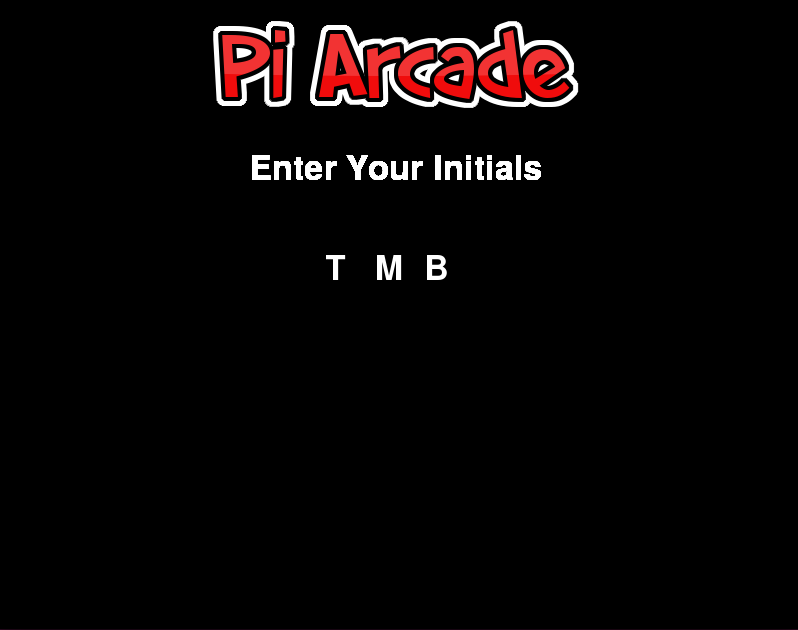
The entirety of the main menu source code is contained within the file pi_arcade.py. This code makes extensive use of the cMenu library extension of PyGame, which enables quick construction of interactive menu screens. The program begins by initializing all of the GPIO pins used by the arcade peripherals, i.e. the joystick and 10 external tactile buttons. All of these inputs are connected to the Raspberry Pi through pull-up networks and have callbacks that are registered to trigger on the falling edges of any of these input lines. After initializing the GPIO pins, the program initializes 1 channel of the pygame mixer which enables music and soundbyte output of 44.1kHz raw uncompressed audio files to the external speakers in the arcade case via the 3.5mm jack. The program then solicits initials from the user so that session data can be associated with a particular user, as shown in Figure 9 below.
After entering initials, the system enters the main menu selection FSM, from which the about screen, high score screen, EmulationStation, and custom Python PyGame games can be entered, as shown in Figure 10 below.
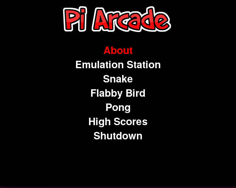
The FSM is very straightforward and follows a simple star architecture. From the main screen, the user can enter one of 7 other states, and from those other 7 states, the program can only ever return back to the main screen (with the exception of the shut down state). The first of these states is the about screen, which displays the names of the project’s developers, the date of its development, as shown in Figure 11 below.
From this screen, the main menu can be re-entered by pressing the A button on the arcade station. The second of these states is the EmulationStation state. When this option is selected, the program turns off the background music and performs an os.system call to run the EmulationStation program from the terminal using pi user privileges. Upon exiting EmulationStation, the program will then turn the music back on and re-enter the main menu state of the FSM. The third, fourth, and fifth game states are the snake, flabby bird, and pong game states, respectively. When any of these states are entered, the main menu screen music is paused and the music for that game is played before invoking the main method of the game’s module. Upon return from the game, the main menu screen music is turned back on and the FSM enters the waiting state. The sixth game state is the high score state. Upon entering this state, a screen pops up showing the top 7 high scores for both the flabby bird and snake games, as well as the respective player initials for those scores, as shown in Figure 12 below.
These scores persist even when the device is shut down and restarted since the data is stored within the Linux file system as a .txt file. The seventh game state is the power off state. When the user enters this state, and os.system call runs the “sudo poweroff” command which gracefully shuts down the entire system so that it can be unplugged from the wall without the risk of destroying regions of memory. Implementing this FSM was fairly straightforward - one of the only issues that we ran into was running the os.system commands with the appropriate user privileges. For example, the EmulationStation program call required that the invoking user not be the super user.
For our custom Python program, we created three separate PyGame games: snake, flabby bird, and pong. For each of these games, all code is contained within a separate Python module with a main function that can be called by the main menu FSM to begin execution of the game. All of these games were tested through extensive play-testing. When trying out each game we intentionally tried to enter as many edge cases as possible to ensure that our programs were robust to unconventional input sequences.
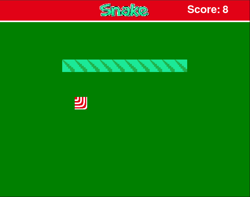
The snake game is designed to run at 20 frames per second. At each frame, a game update function is called to evaluate whether or not the snake sprite is overlapping with the food, or if the snake has collided with itself. The snake data structure is simply an object with length, step, x, and y-coordinate fields that encode the length of the snake, the number of pixels the snake traverses in one frame, the list of x-coordinates for the snake’s blocks, and the list of y-coordinates for the snake’s blocks. When updating the snake’s position, each entry in the x and y-coordinate fields is simply shifted over by one in the direction of the 0 index. A new entry is then prepended to the array for the block that the snake’s head has just moved to. After updating the game state, the program simply checks to see if the user has pressed any of the joystick buttons on the arcade station and runs to the appropriate movement command to change the current direction of the snake. On the screen, this movement will be realized when the next frame is drawn. Figures 13 and 14 below demonstrate the main snake game screen as well as the game over screen, which is entered whenever the snake collides with itself.

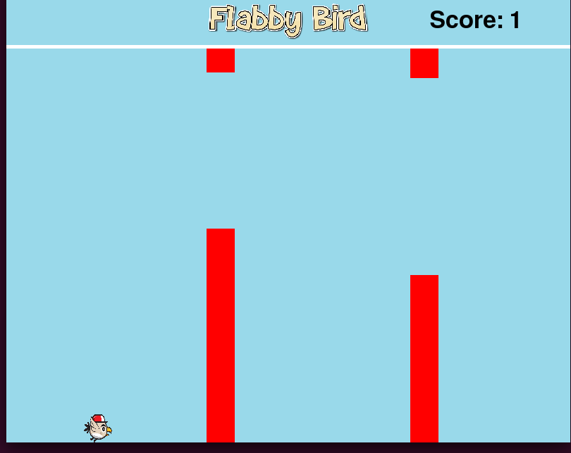
The flabby bird game operates on a similar architecture but at 60 frames per second, with more complex sprites, and with side-scrolling. Within the main function of this program, Player and Level objects are instantiated before entering a while-loop. The Player object encodes the image, score, x-velocity, and y-velocity for the main character sprite. The level object creates a randomized level that gets progressively more difficult as time progresses within its init function. At initialization, the level creates a list of length 3 vectors that encode the x locations of each enemy sprite and wall within the game, as well as the relative heights of each of the barriers that constitute those walls. Using the randint function and a counter that is incremented for each new wall that is drawn, the heights of these barriers are chosen so that the gap will always be large enough for the main character sprite to traverse but will progressively get smaller for each subsequent wall that is drawn. This is accomplished by narrowing the range of random realizations for the heights of those barriers using the current counter value. After generating the x-locations and heights, the initialization function then randomly determines whether or not an enemy bird sprite or a wall will be placed at each of those x-locations using the randint function. The probability that any given x-location will contain an enemy bird sprite is 1/3, and the probability that it will contain a wall is 2/3. Within the main while-loop of the program, PyGame’s event flags are checked to see whether or not the A button has been pressed on the arcade station. If so, then the jump function is called for the player sprite, which simply sets y-velocity of the bird to -9 (upwards on the screen). For each subsequent frame, this number is reduced by 0.35 to simulate gravity. After evaluating whether or not a jump has occurred, all of the sprites on the screen aside from the main player’s sprite are shifted to the left by 4 pixels to give the appearance of side-scrolling. The game then evaluates whether or not the main player’s sprite has collided with any of the enemy sprites or walls within the game. If so, then the game_over flag is raised and the program exits the main while-loop of the program. When this occurs, the game over music is output on the arcade station’s speakers and the game over screen is displayed alongside the user’s final score. From this screen, the user can return to the main menu by pressing the A button on the arcade station. When constructing this program, we found that the most difficult part was ensuring that, when randomizing the positions and sizes of all of the walls and enemy sprites that the game was still playable. A sample screenshot of the gameplay can be seen in Figure 15 below.
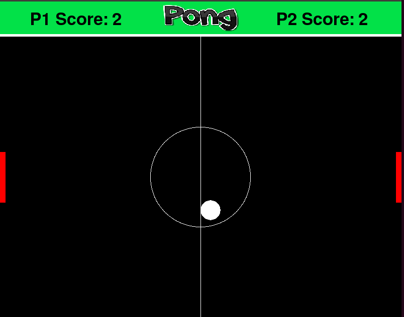
The final custom game that we created for our program was an adaptation of pong. Before entering the while-loop for this game, the program initializes the paddle positions to be half-way down on the game field and randomly chooses a starting direction and velocity for the ball at the center of the screen. Within the while loop, the program first redraws the entire screen based on game updates. First it blits the screen with a black fill, then redraws the center circle and left/right side boundaries. Then the program checks all of the paddle velocities and positions to make sure that they cannot leave the bounds of the playing field. Lastly, the draw function redraws the ball according to its current position and velocity, and evaluates whether or not a collision has occurred between the ball and the paddles or walls. If the ball has reached the left or right-hand walls, then the ball will disappear and a new ball with randomly-generated starting velocities will spawn at the center of the playing field. After updating the game state, the main while-loop of the program checks to see whether or not player 1 or player 2 have pressed the up or down keys for their paddle on the arcade station buttons. If either player has pressed their respective up key, then the y-velocity of that paddle is set -5. Similarly, if either player presses their respective down key, then the y-velocity of that paddle is set to 5. If the up or down keys for a given paddle are not depressed, then the y-velocity for that paddle is set to 0, causing the paddle to stop moving on the screen. Lastly, at the end of each iteration of the while-loop, the player scores are checked to see if either player has reached the max score of 3. If so, then the game over music soundbyte is played and game over text is displayed on the screen with the winning player’s name. By pressing the A button on the arcade station, the user can then return back to the main menu screen. Implementation of this program went more smoothly than for snake and flabby bird - our first implementation contained all of the necessary functionality and required minimal aesthetic changes to reach the final design. Figure 16 below demonstrates an example of what the main pong screen looks like during gameplay.
Testing
Since Python is a run-time language, debugging the system required a great deal of play-testing. We played with the system and tested all FSM states accessible by the user. During this testing processes, we found that once we launched the EmulationStation and tried to play a ROM, it would fail to display the game. However, if we launched EmulationStation outside of our Python program, the games would launch properly. To resolve this issue, we ran the following command every time we launched EmulationStation within our Python program: sudo emulationstation --debug > debug.log 2>&1. By doing this, a log file was generated which we could cross reference between the successful and unsuccessful launches of the system. By parsing through this, we found that there was an issue with the default display screen being tty when launching from the Python script. Within opt/RetroPie-Setup/scriptmodules/supplementary/runcommand/runcommand.sh we changed tty to tty1 in locations suggested by the log files and found that this was the solution to our issue. From this, we learned the utility of log files and how properly use them to debug large terminal outputs. Without them, we wouldn’t have been able to parse the terminal outputs manually to discover this error.
Results
Ultimately, we were successful in creating a fully embedded system with three custom built Python games, along with the pre-built RetroPie EmulationStation housed in a custom-made arcade cabinet. Our initial objective was to create a two-part system where the user would be able to launch pre-built emulation software as well as our own Python PyGame games, and that is exactly what we were able to accomplish. We did not initially set a goal for number of Python games we needed to create because we were not sure how complex the integration of our custom system with the pre-built EmulationStation would be. That being said, we were able to make three well-working games, incorporate our own sprites, and create other graphics and backgrounds for a well-polished aesthetic in a fashion we are quite proud of. Additionally, we were able to implement a high score tracker so that, upon boot up of the system, a user could input their initials to save and compare their session’s scores to scores from other players that have used the machine. Overall, we were very satisfied with our final project design and believe that it showcases the power of Linux-based embedded systems such as the Raspberry Pi, as well as the extensibility of the PyGame development library.
Conclusion
The project was a great success. We built a working embedded system that uses a combination of pre-built software and our own Python scripting. Through this process, we learned a great deal about peripheral set up of the Raspberry Pi, not only through making the composite video out on the Raspberry Pi function properly but also through the GPIO input configuration and manipulation. We gained a great deal of experience working through PyGame libraries which not only tested logical game making but user interface development with a solid look at aesthetics. In addition, this project gave us the chance to work through CAD modelling and improve on our skills in that regard. During the process of testing, there was nothing that did not work at all. There are areas like with the GPIONext daemon that would benefit from a further study of options, but nothing explicitly failed in a way which we didn’t create a work around.
Future Work
While we are happy with our final arcade station design, we believe that there are plenty of improvements that could have been made. Firstly, implementing a new daemon to map GPIO pins to a virtual joypad would be the most important upgrade. Adafruit has produced a script called RetroGame which may be more promising than the GPIONext daemon and may be worth exploring. Additionally, it would be nice to have a different power management system. In our current design, there is a small extension cord placed within the arcade cabinet that allows separate power bricks for the screen, speakers, and the Raspberry Pi to be plugged in. The screen and speakers both take in 12V but the Raspberry Pi requires 5V. A more ideal power management system would be to have a 12V barrel jack input in the back of the cabinet for the screen and the speakers, with an internal DC-DC switching regulator from 12V-5V for the Raspberry Pi. This would make a much cleaner power system for the user, and free up a great deal of space for the internal cabinet. Thirdly, we would invest in a higher quality joystick and buttons. The ones we purchased work for the system, but with only a month or so of use, we have found that on rare occasions the buttons stick slightly. Lastly, an unnecessary but interesting addition to the arcade would be to integrate the external entertainment center package “Kodi”. Kodi is a fully-developed Raspberry Pi program that allows the user to watch movies, play music, have weather information displayed, and much more. We thought about including Kodi in our final project design but we had issues with input external peripheral to control signals that Kodi could understand. The Kodi software package is programmed to accept keyboard inputs, but can also be configured for other controllers like those for Xbox or Playstation. In our testing, we were unsuccessful in getting Kodi to detect the GPIONext daemon, and thus could not have it controlled with our arcade-style buttons. We chose to leave it out of the arcade for now, but if the Adafruit RetroGame package is capable of interfacing with Kodi through some sort of virtual keyboard, then it might be a preferred alternative to the GPIONext daemon.
Appendix
Budget
| Item | Acquired From | Price |
|---|---|---|
| Arcade Buttons and Joystick | Amazon | $19.99 |
| Screen | Amazon | $28.99 |
| Speakers (repurposed) | Ebay | $8.99 |
| Plywood | Home Depot | $22.42 |
| 3.5mm 4-Pole Audio Plug Terminal Block | Adafruit | $2.50 |
| 3.5mm Stereo Audio Jack Terminal Block | Adafruit | $2.50 |
| RCA Female Jack Terminal Block | Adafruit | $2.50 |
The total spendings for this project were $87.89. The Raspberry Pi and the wires required for connecting the buttons to the GPIO pins were found in lab and did not need to be included towards our $100.00 budget.
Code Listing
Below is all of the code that is on the Raspberry Pi. This includes the code for the main menu screen, the games, and all the images and sprites used.
Pi Arcade DirectoryDivision of Work
During this project, Dhruv worked primarily on hardware aspects of the project where he designed and assembled the arcade cabinet. He also worked to integrate the pre-built EmulationStation and perform the custom configurations that enabled the embedded system to function on the Raspberry Pi with the given hardware. Tim worked primarily on software, focusing on creating the Python script that integrated the entire project together. Tim built out the menu screen and all three Pygame games. Throughout the project, Tim and Dhruv helped out one another with their given responsibilities, but above lists the general division of work.