Magic Selfie Mirror
A Project by Siyao Liu and Junyi Huang.

Project Objective:
The magic selfie mirror is a mirror that can send greetings, display date, humidity, temperature information and take selfies when you use it. Some people like taking selfies after finishing wearing makeup, the magic selfie mirror just combined the two processes together to make life easier and more fun.
Introduction
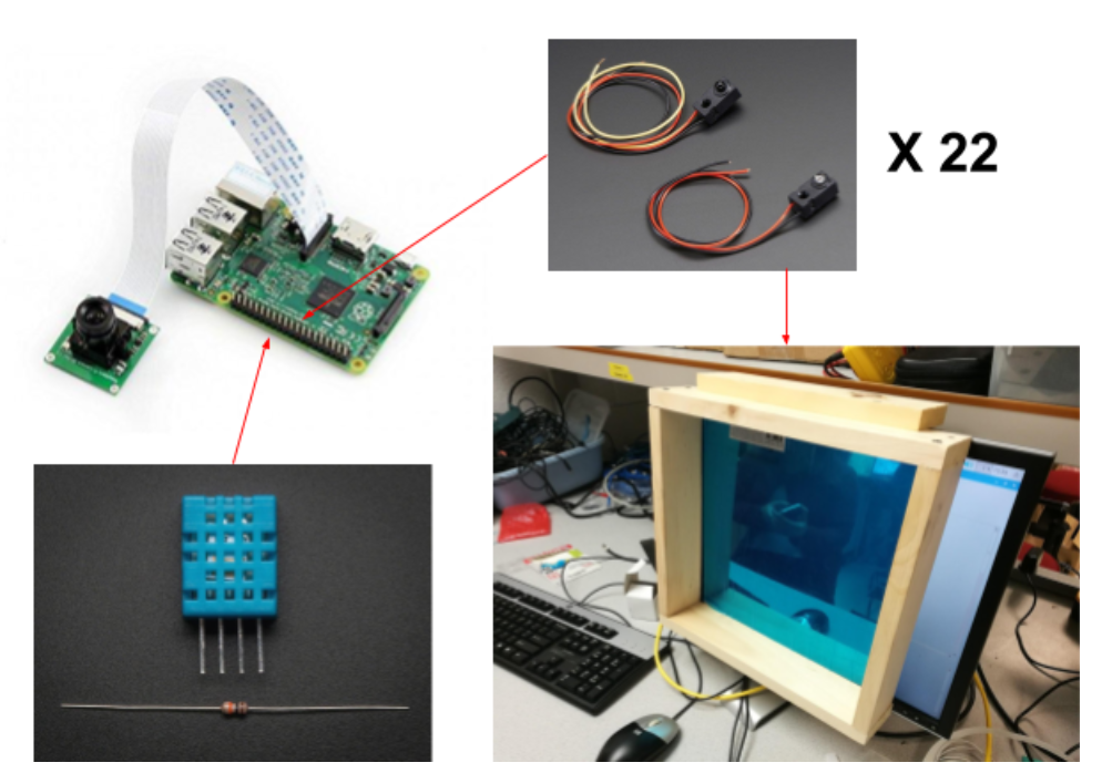
In the hardware part, a sheet of see-through mirror was used as the basic mirror to be looked at and a monitor was put behind the mirror to display the information, preview the camera and see the selfies taken before. A square wooden frame was built to surround the mirror, and 22 IR beam break sensors were screwed into the frame to detect gestures above the mirror to switch functions and filters. Instead of connecting directly to the RPi3, four 8-to-3 priority encoders and two 74LS00N NAND gate chips were used to convert the signal from sensors into two numbers indicating the position of user’s hand. A Humidity & Temperature sensor was used to get current humidity and temperature. What’s more, a PiCamera was connected to the RPi3 to take selfies.
In the software part, a homepage was designed to send greetings and basic date, temperature and humidity information when user wave hand in front of the mirror. The information is divided into three parts, wave hands above the certain information can delete it from the mirror. The deleted information can come back if another wave gesture is detected. Keep pointing to the left corner would enter the camera mode. With swipe gestures above the mirror are detected, different image effect filters, like cartoon, emboss, sketch, would be applied. By pressing a GPIO button, a selfie would be taken and saved and a preview of the selfie would display at the corner of the mirror. Pointing at the selfie preview, the mirror would enter the photo album mode. In this mode, swipe gestures were still used to preview the next or the previous selfie. What’s more, the word “resize off” would show up in this mode. Pointing at this phrase, it would turn into “resize on”, and the selfies could be zoomed in and out controlled by gestures. The ratios of zoom-out and zoom-in were determined by the range of gestures. In each mode, there were always a “quit” word in the screen, putting hand in front of this word could return to previous mode.
Design
System Overview
The Magic Selfie Mirror System is consisted of Raspberry Pi 3, four 8-to-3 priority encoder chips, two 74LS00N NAND gate chips, 22 IR beam break sensors (3mm LED), a PiCamera, a Humidity & Temperature sensor, a display monitor, a sheet of see-through mirror, and a wood frame to hold the sensors.
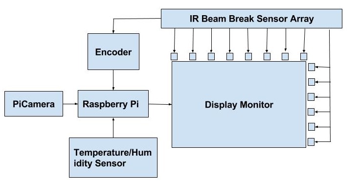
General System Diagram
Hardware System
Since the IR sensors is used to read gestures like hand wave, left slide, right slide, up-left slide and down-right slide, only few IR sensors cannot satisfy the requirement. So multiple sensors should be added in our system. In the Adafruit shop, there are two types of IR sensor, 3mm LED and 5mm LED, with sensing distance and price 10 inch, $1.95 each and 20 inch, $6.50 each respectively. Because the budget constraint of $100, we decided to use eleven pairs of the 3mm type sensor on both up-down and left-right direction of the mirror and keep the mirror in a square size with a side length of 10 inch. Since all the sensor output should connected to GPIO pins and it’s hard to find 22 empty pins to use as input, extra encoder chips should be used to shrink the 22-way signals into two groups of 4 digit signals. Therefore, we ordered 22 3mm IR beam sensors, 4 8-3 encoder chips, a 12’’x12’’ see through mirror sheet, and borrowed two NAND gate chips from the lab.
Hardware Design
Since most of our system is based on gesture control, complete the hardware part should be the initial work of our project.
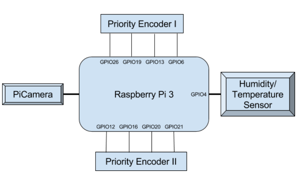
GPIO Connection Diagram
Each pair of IR sensor is a combination of an emitter and a receiver. Both of these two part should connect to 3.3V - 5.5V power, and the receiver has another extra white line to export signal. The receiver is open collector and need to connect to a pull up resistor. So in the program, the build in pull up resistors of the GPIO pin should be turned on. According to the datasheet, the sensing distance of the sensor is 10 inch. However in fact, after testing, we found the sensor could work precisely in a range of 12 inch, which is exactly the width of the monitor in the lab 239. So we decided to make a wood frame of 12’’x12’’ and borrow the monitor in the lab .
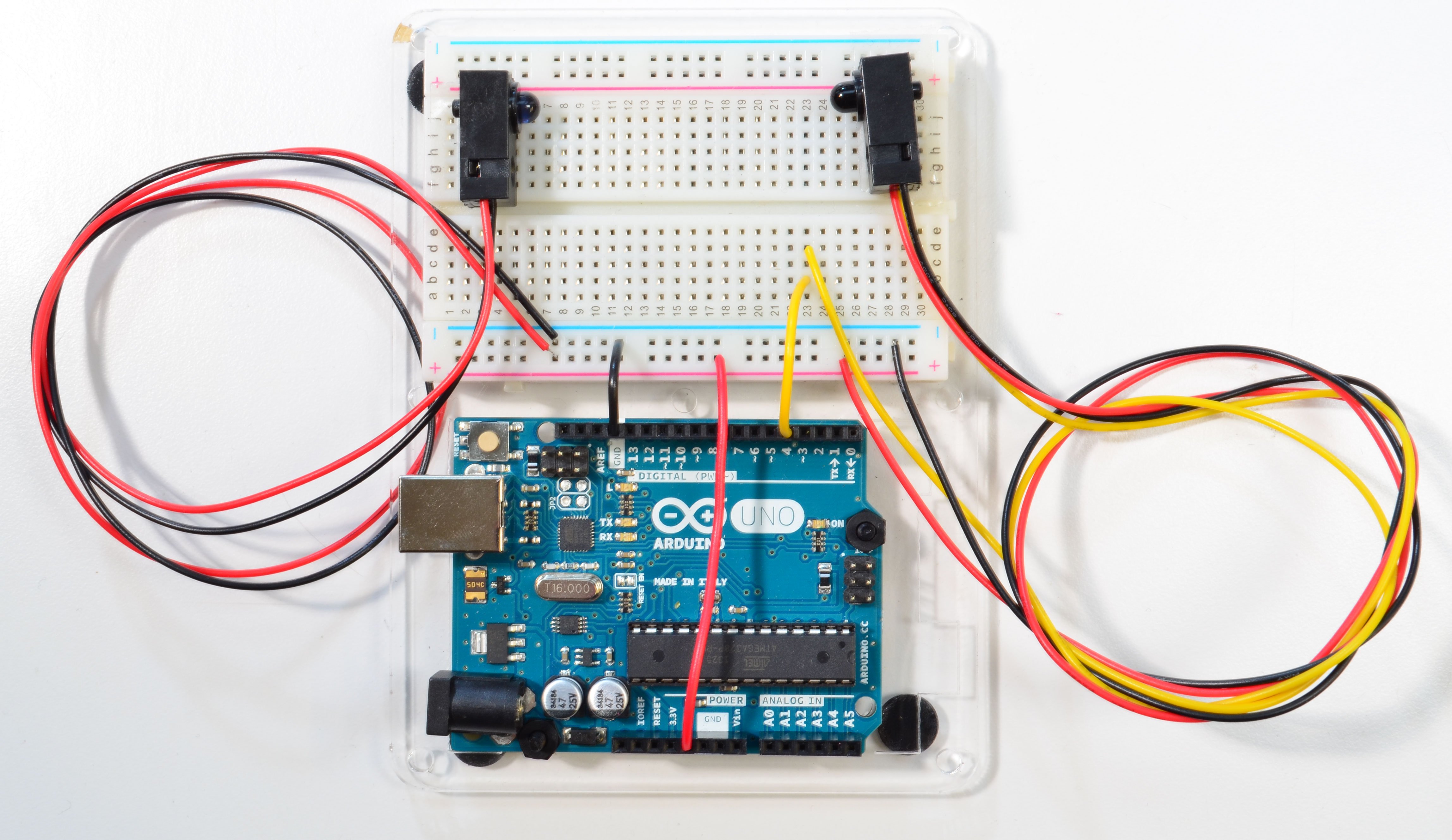
IR Beam Break Sensor Circuit [2]
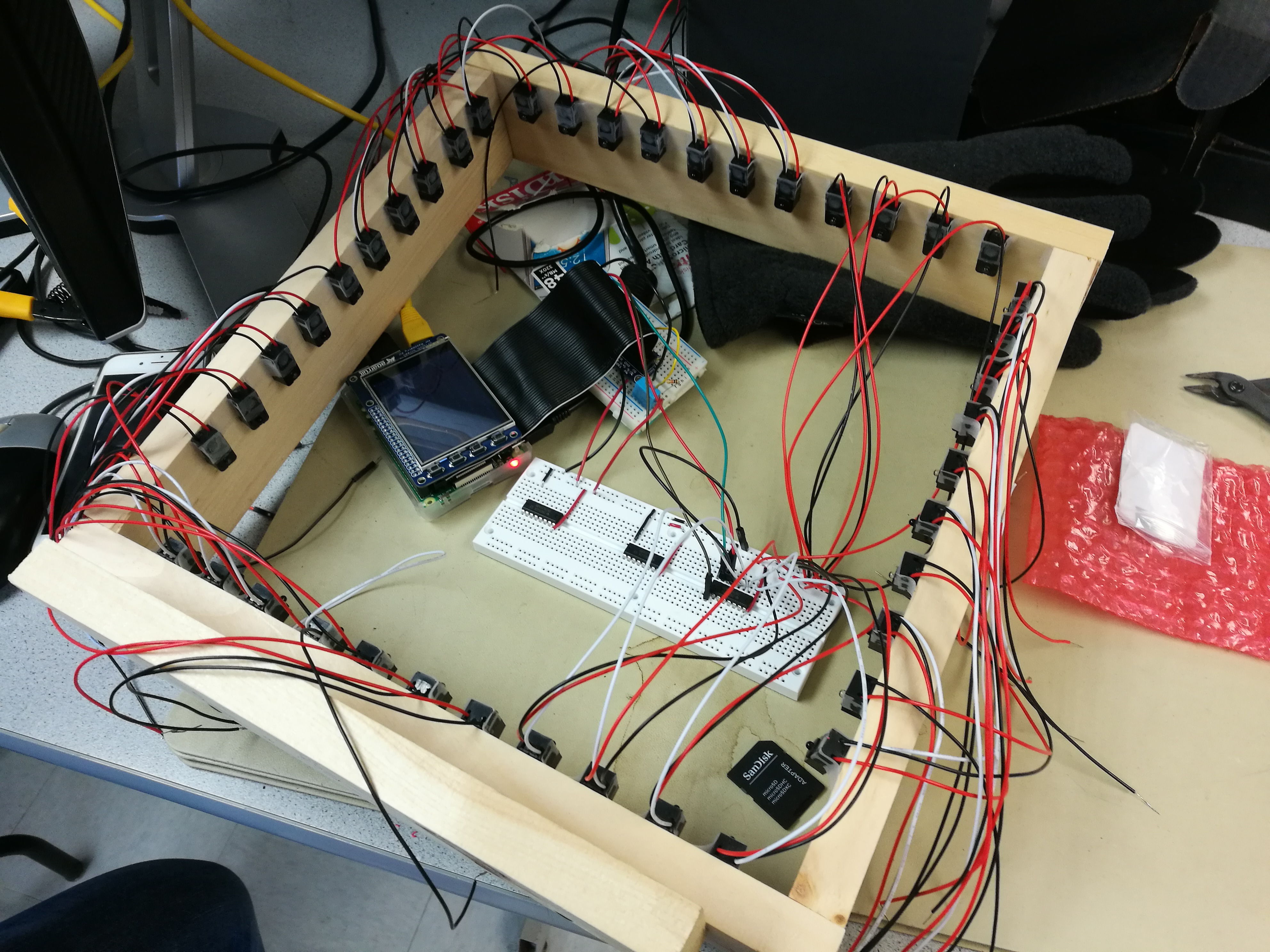
IR Beam Break Sensor Arrangement on the Frame
At the very beginning, we planned to use only three 8-3 encoders to process the 22 input signals from the sensors. However, in this way, three up-down sensors should share the same encoder chip with three left-right sensors. The final output of the three encoder chip would take up 9 GPIO pins and it would be extremely confused to read the position of the broken beam from the 9 digit signals. To improve, we decided to use four 8-3 encoders to build two 16-4 encoders. In this way, the output digit number could shrink to 8, and each 16-4 encoder could serve for one group of sensors. When the user put their hand in the middle of the frame, the system can easily read the coordinate of the hand’s location.
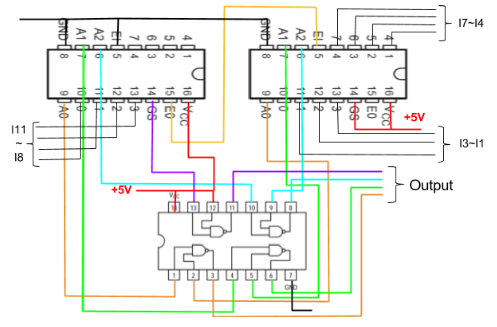
16 to 4 Priority Encoder Circuit
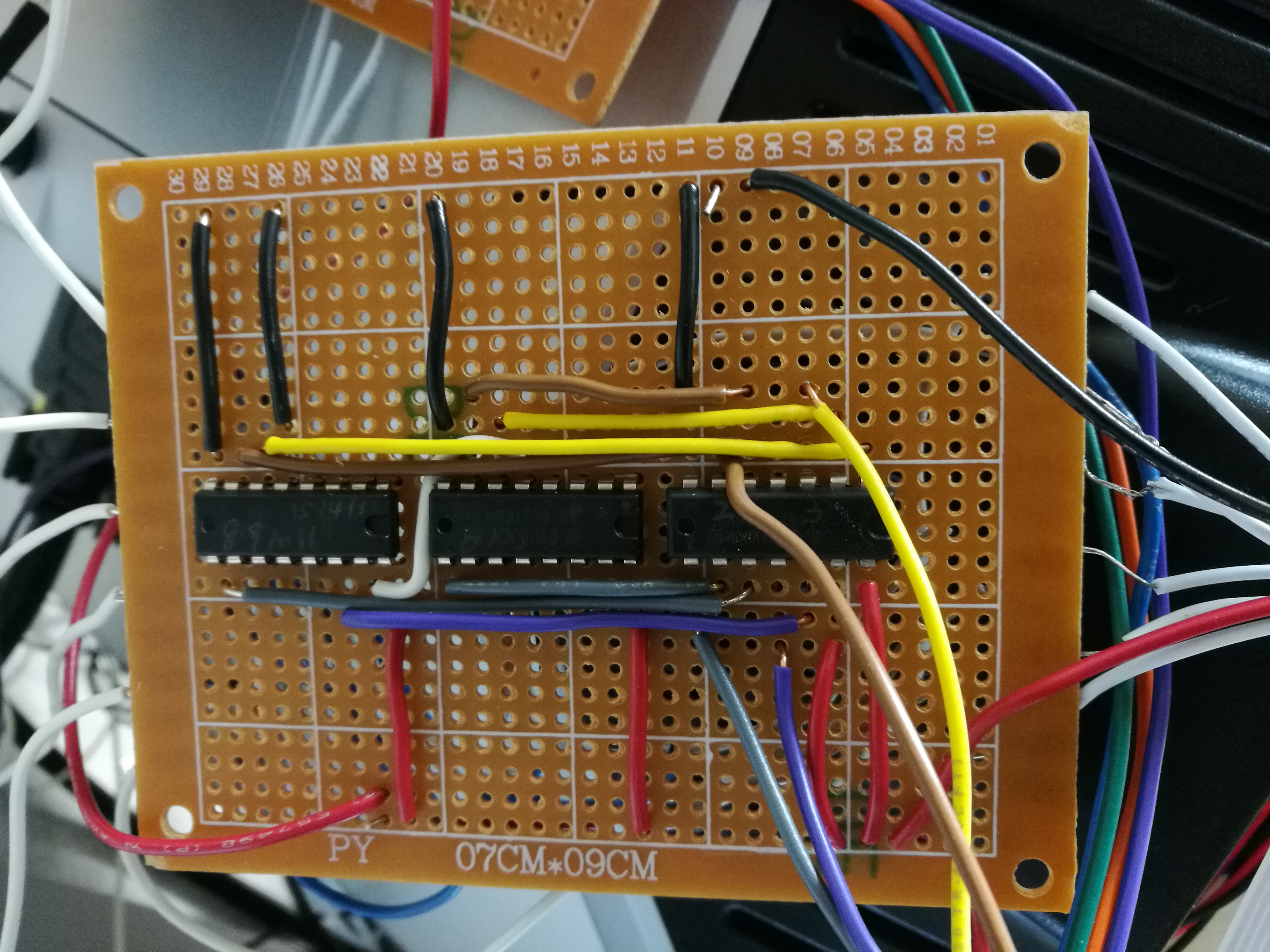
16 to 4 Priority Encoder Circuit Board
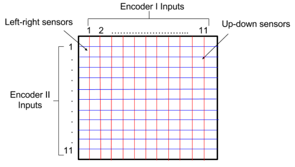
IR Sensor Matrix
The wire connection of Humidity and Temperature Sensor is much more easier and it only takes up one GPIO input.
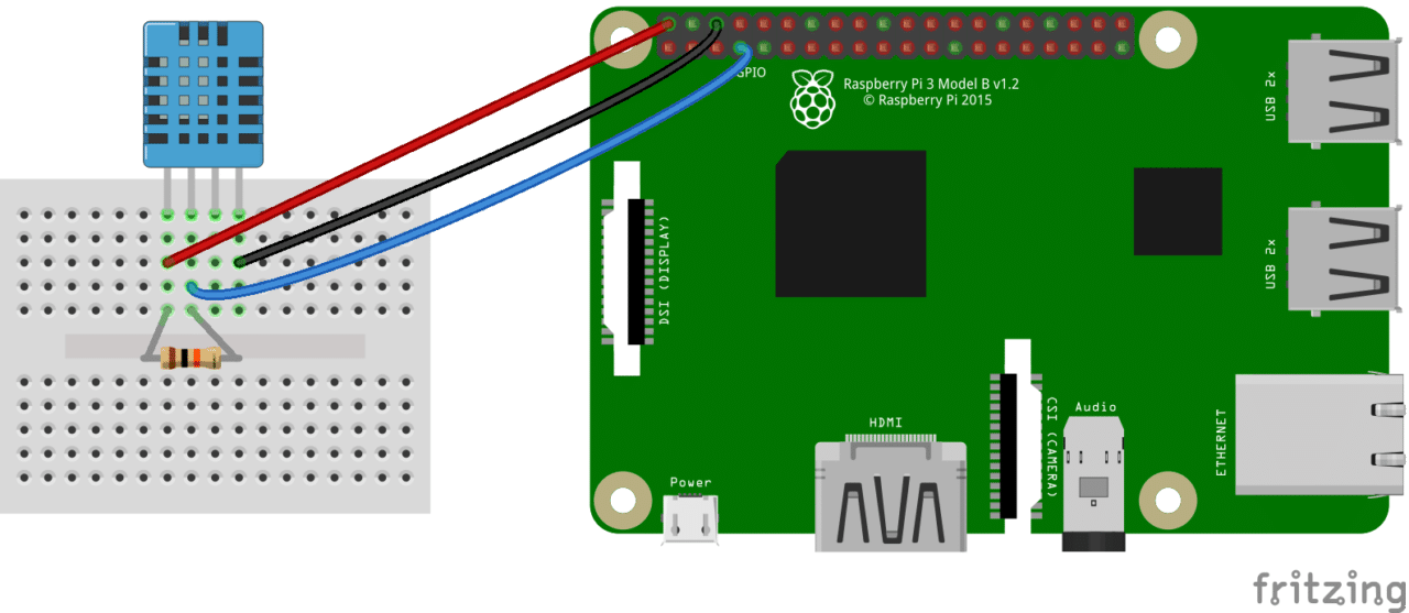
DHT11 Circuit Coonection [3]
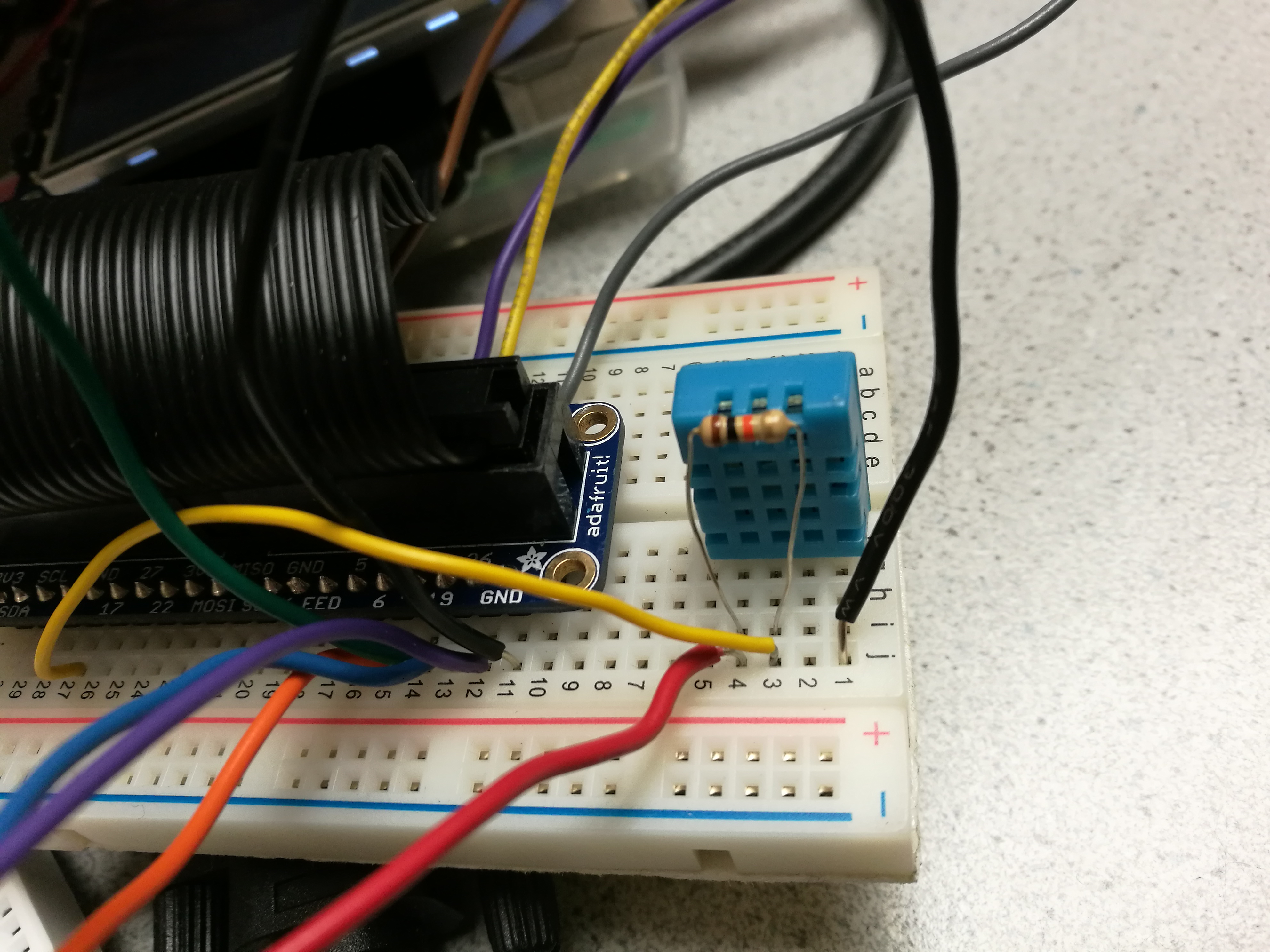
DHT11 Sensor On Circuit Board
Software Design
Our program is combined of different parts include Magic Mirror content control, PiCamera control, and gesture recognition.
The basic function of the system is gesture recognition, all the other functions is based on it. To control our system, we need to read and track the position of the user’s hand. In the hardware design, we already stated that we set the beam sensor as a matrix, and each group of the 11 sensor is processed by a 16-4 encoder. Take the 11 up-down sensors for example, if the 10th beam is broken, the input of the encoder is “01000000000” and the output of the encoder is “1010”. The four digit binary number will be inputs of four GPIO pins. In the program, the four digit number will be translated into decimal format. So if the 10th beam of the up-down sensors and the 8th beam of the left-right sensors are broken, we could get a coordinate (10, 8). When all the beams are not broken, the output of the coordinate would be (0, 0).
A queue data structure is implemented to read the left/right slide gesture. The queue is initialized as [0, 0, 0], and in a while loop that only last for half a second, if the output of the up-down sensors encoder value is not 0, we insert the new value in the head of the queue with insert() function and call pop() function to maintain the length of the queue. If there is some point, the three values in the queue are increasing, set the queue value back to [0, 0, 0] and output a “left slide” signal, if the three values are decreasing, then reset the queue value and output a “right slide” signal.
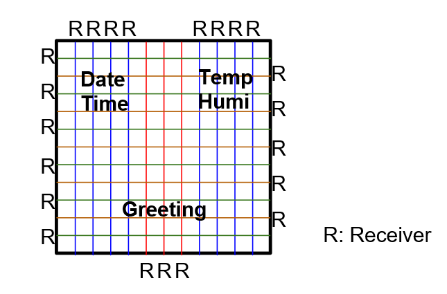
For Magic Mirror content, we do not directly install the existing Magic Mirror package on Github[4]. Instead, the environment information is obtained from a Humidity and Temperature Sensor, the time and date information is transformed from time.ctime() function, the greeting message is printed by a greeting function. All the magic mirror content is displayed on a pygame screen. Three functions named Greeting(), DHT(), and Time() is defined at the very beginning of the program and kept being called in a while loop to let the three parts of information shows up on the screen. At the mean time, the while loop keep detection whether the IR beams near those messages are broken or not. If those beams are broken by a gesture, like a touch or a slide, the message on this location would disappear on the screen by stop calling the relative function. If the beams are broken again, the function would be recalled and the content would go back. There is also a little camera icon at the left-down corner of the screen, if user keep point to this corner for a while, the system will automatically open a picamera previewing window at the top of pygame screen and enter the selfie mode.
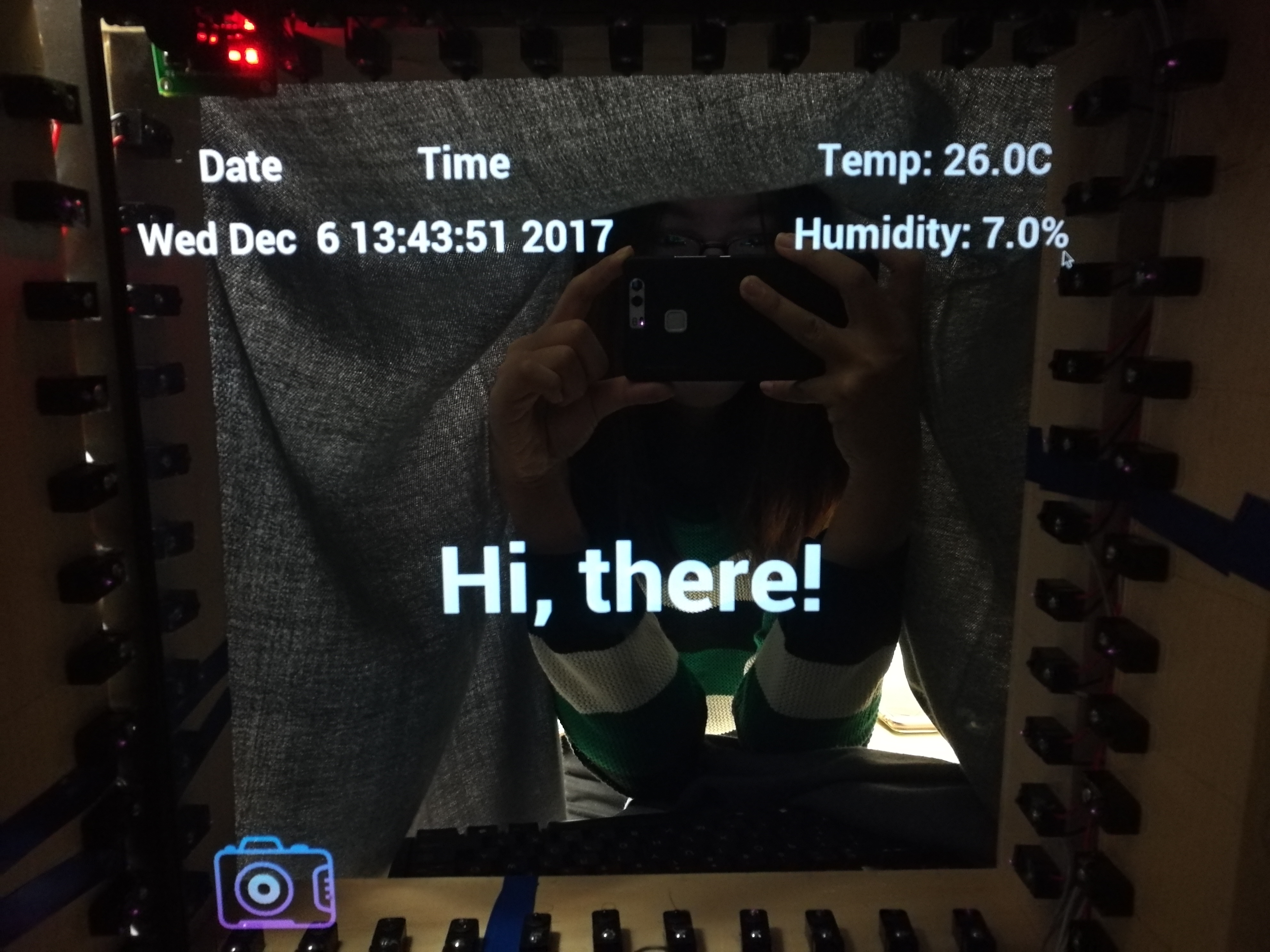
Magic Mirror Home Mode
PiCamera is a very handy and programmable module. In our system, it is put at the up-left corner of the wood frame and used as a selfie camera. In the program, picamera is mainly controlled by gestures detected from the gesture recognition module. When system comes into the camera mode, if a left slide or a right slide gesture is detected, the picamera will change the image effect. The system embedded 8 image effects, and users can take pictures by pressing a GPIO button. All the pictures would be named as 1.jpg, 2.jpg, 3.jpg, etc. The latest picture will shrink into a small size and shows up at the right-bottom corner of the screen, just like our smart phone does.
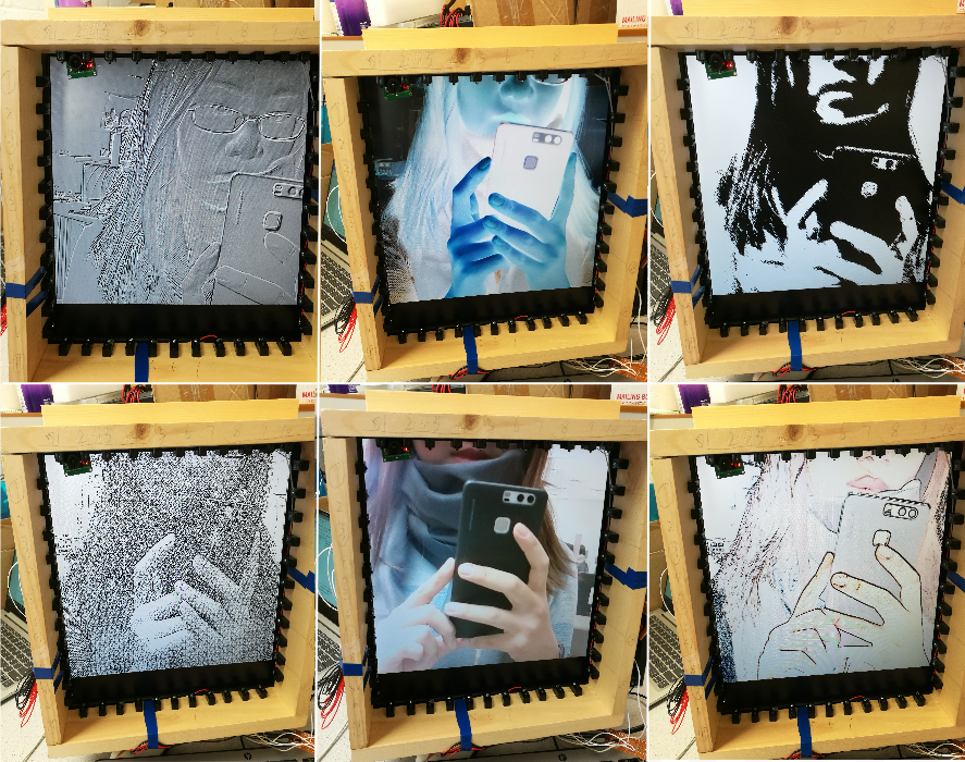
Different Image Effects
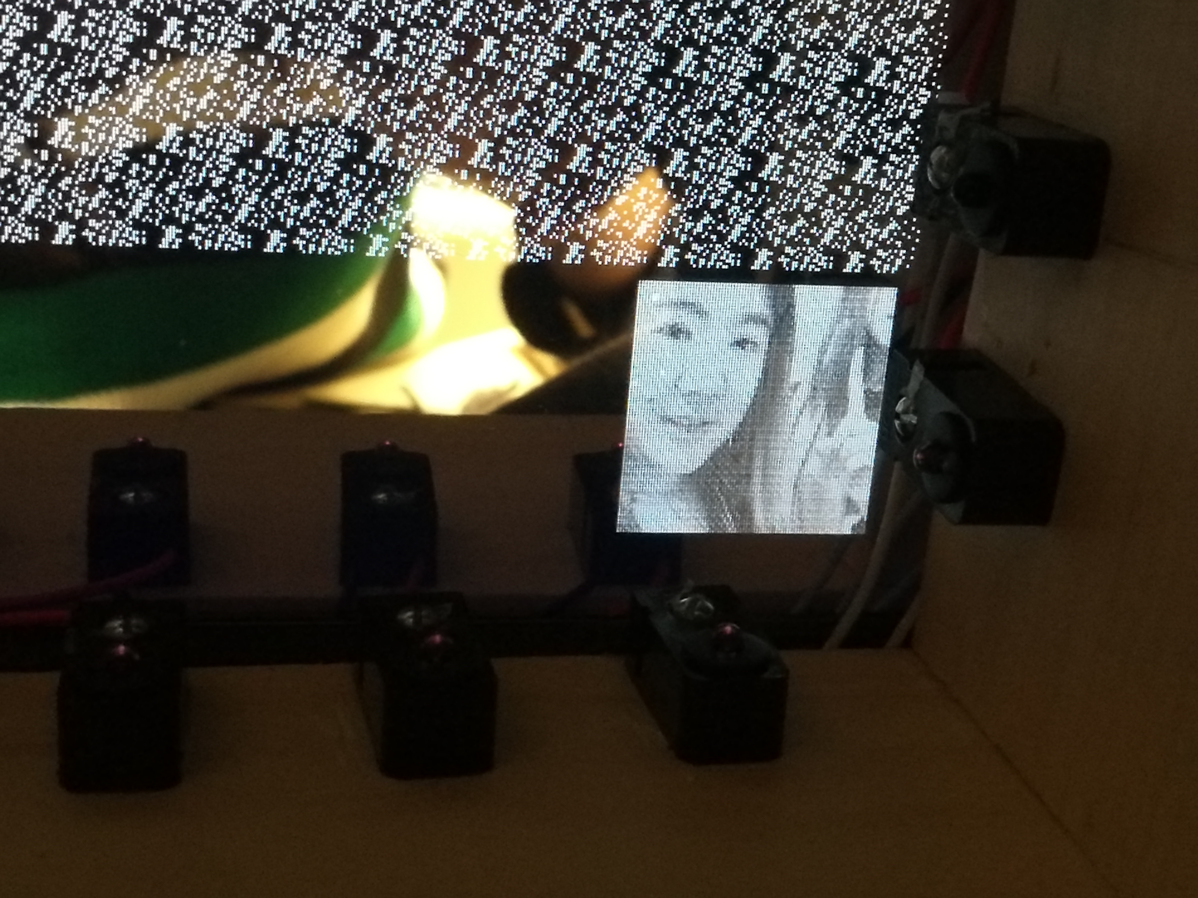
Small Size Last Picture at the Corner
User can also get into the photo album mode by pointing to the small picture icon at the corner. In this mode, picamera will temporary stop previewing and the pygame screen will shows the original size latest pictures we took before. Left slide and right slide are still effective here. If a right slide is detected, the screen will show the nearest prior photo, and if a left slide is detected, it will show the nearest following photo. If the photo on the screen is already the very first/last photo we took, the system will not reflect to a right/left slide gesture. What’s more, at the corner of the screen, a phrase “resize off” shows up. By point to this phrase, it will change to “resize on”, and the system will thus get into the resize mode.
Resize mode let user zoom in or zoom out the picture with gesture control. If the sensor matrix detected user’s hand (or anything break the IR beam) move from the right-down corner toward the left-up corner, the size of the picture will shrink with the motivation. If the hand move backward, from left-up toward right-down, the picture will expand with the motivation. The more you go, the more changes the picture size. To complete this function, two arrays are implemented to record the coordinates at two neighboring time points. The arrays are named as “first” and “second”, both of them are initialized to [0, 0]. If the system detected any returned coordinate other than (0, 0), then sent the value of “second” to “first”, and update “second” with the present coordinate. With the two coordinates, system will calculate how large the size should change and use function pygame.transform.rotozoom() to shrink or expand the picture.
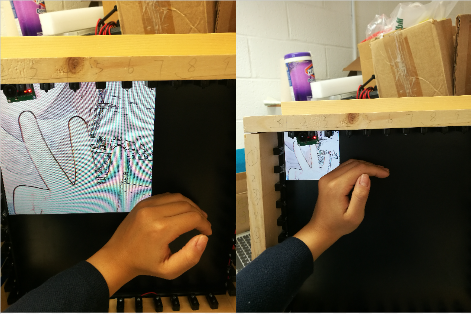
Resize Image
There is always a quit “button” on every mode locate at the middle bottom part of the screen. By pointing to this position for about half a second, the system can quit from resize mode to album mode, quit from album mode to camera mode, or quit from camera mode to the magic mirror home mode.
Testing
We have created several programs to test different parts of the system. Camera.py is used to import picamera library, control picamera, call different image effects, set contrast and brightness, change exposure mode and awb mode, rotate the camera, set resolution and change the location of the preview window, annotate the photos, take photos and videos and store them with given names.
Image.py is used to test resizing function on the pygame screen. In this program, we load the image from the directory only once at the beginning and keep calling function scale(), soomthscale() or rotozoom() to rescale the image. However, all those three filters will reduce the quality of the image badly. If those filter process image for more than ten times, the image will get gloomy and blurred and even hard to recognize the human face. So in the final program, a while loop is used to resize the image and the image data is reloaded every time in the loop.
Dhttest.py is aim to test the Adafruit_DHT library, which we downloaded from Github. It turns out that the library is very easy to use. It only takes up one GPIO pin to get both the current humidity and temperature information. It should be noted that the sensor should also set up a pull up resistor.
Irtest.py tests the real sensing distance of the IR sensors. It turn out that the sensors could works perfectly in a range of 12 inch. What’s more, the sensor is not working “in pairs”, which means that in a sensor matrix, if user break the beam near the emitter side, the receiver still could read the beams launched from other emitters. So the system will be much more sensitive if user gesticulate near the receiver. To get the best effect, we set the position of the sensors as the following picture shows.
Location of Receivers
Testinput.py is help to check if the frame and circuit has been setup properly. If the hardware works well and none of the beams are broken, the output of the program should be (0, 0). If some beam is broken, it could return the largest coordinate of the beam broken point since the encoder we use is a priority encoder. For example, if user’s hands are put at points (2,1) and (8, 9) at the same time, the system will only print (8, 9) on the command window. This program really helps a lot in our experiment. If the main program does not work, we can always use it to test if there is anything wrong in our circuit. Normally, if we do not touch the monitor and one of the returned coordinate is 15, it indicates the relative encoder has not been powered properly, and if the returned coordinate is between 1 and 11, it may indicated that the wire of the sensor is separated from our circuit board.
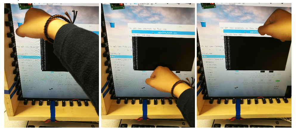
Read Coordinates (2, 1), (7, 8), and (8, 2) on the Sensor Matrix
Result
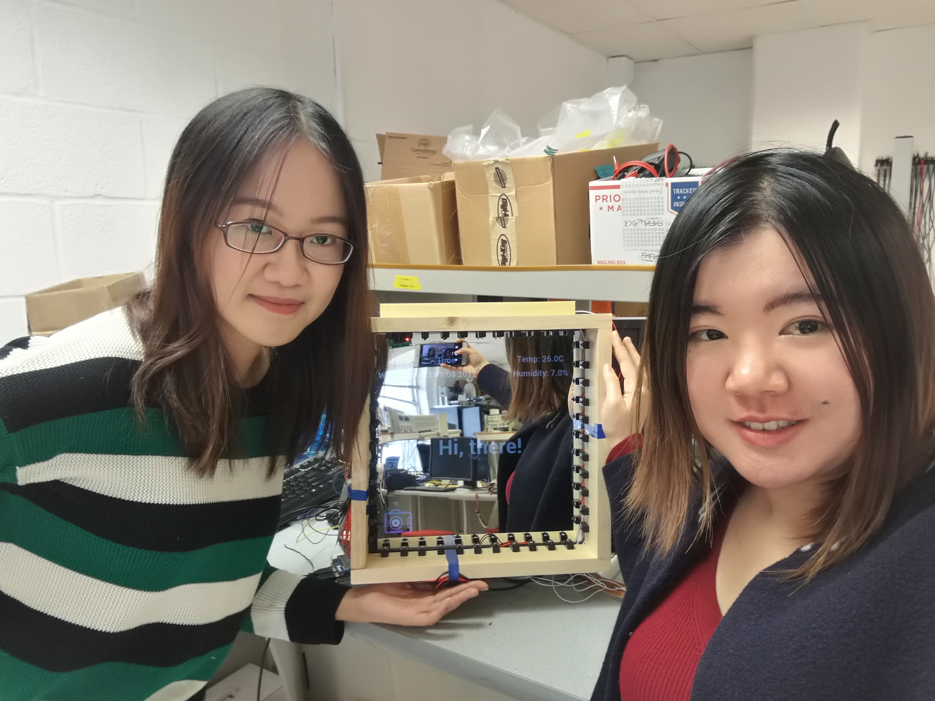
Group Members and The Mirror
The magic selfie mirror realized all the goals in description, including the greeting mode, basic mirror mode, camera mode, and pictures previewing mode. Users can wake up mirror to get greetings and basic daily information about date, temperature and humidity to help them choose which product to use, clear up the mirror to make up and enter the camera mode to choose different filters and take selfies. After taking selfies, they can enter the picture previewing mode to preview selfies, the pictures could be zoomed out and zoomed in according to their gestures range. All operations except taking pictures could be done by gestures, because we want to keep the touch of taking pictures by camera.
Demonstration Video
Conclusion
Our project was accomplished successfully, we figured out how to detect gesture positions and record the trace of gestures in a surface, how to use 8-to-3 encoders and NAND gates to switch two 8-to-3 encoders into one 16-to-4 encoder and improved soldering skills a lot. We really went through a hard time figuring out the circuits and soldering them into board, because breadboards were not firm enough for the beam sensors’ wires, they were too soft to stay in the breadboard. We previously planned to use three 8-to-3 encoders to collect signals from the 22 beam sensors and reduce the usage of GPIO pins in RPi3, but it had the problem that part of the up-down side and left-right side would use one encoder, where two sides were not independent with each other, which may cause trouble with debugging and software designing. Instead we chose to use two 8-to-3 encoder and changed into 16-to-4 encoder separately for two sides so that we could tell which sensor broke down easily according to the position pair.While getting time and humidity information from the sensor, it would need 3-5 seconds to read the temperature and humidity, which hugely delayed the system responding time. Instead of updating the temperature and humidity in every loop, we choose to load the information at beginning, because humidity of a day wouldn’t change suddenly, it may only change daily, not secondly. When the magic mirror was woken again, it would update the temperature and humidity information.
Future Work
Currently we used two 8-to-3 encoders to make a 16-to-4 encoder for the up-down side and left-right side, which could only print out the largest number of the position, so if a hand was putting above the mirror, it can only read the right down corner of the hand, instead of the full hand. The future work would focus on detecting the hand gesture more in detail, like recognizing fist from stretching out fingers, using stretching content to zoom-out the pictures and so on. In that case, the priority encoder may not meet the requirement, because all data of the fist would need to be recorded. Another focus would be putting more sensors in the frame to make the detection more sensitive, right now the 22 beam sensors would require larger scale of gestures due to the sparseness of the arrangements. More sensors and better arrangements would reduce the interaction among beam sensors and increasing the sensitiveness of the whole frame.
Work Distribution

Siyao Liu
sl2928@cornell.edu
Circuit design
Circuit test
Components test and initialization
Program design

Junyi Huang
jh2635@cornell.edu
Building and soldering circuit
Circuit test
Program design
System optimization
Parts List
- IR Beam Break Sensor X22 $38.72
- SN74LS148N-8-line to 3-line Priority Encoder X4 $6.60
- SN74LS00N-Quad 2-input Positive-NAND Gates (Borrowed From Lab 239) X2 $2.36
- See Through Mirror Sheet 12"x12" $14.99
Total: $62.67
References
[1] Snowwhite Picture Resource[2] IR Beam Break Sensor Circuit Connection
[3] DHT11 Sensor Circuit Connection Guide
[4] Adafruit_DHT Library Download