Big Red Bot
Objective
The primary objective of the project is to create a robot that can be maneuvered remotely using any device connected to the internet, in a secure manner. The bot employs a Raspberry Pi 2 Model B at its core, gives a live video feed using camera module and hosts a Flask server that contains the GUI to control the bot. The Flask application also conducts user authentication to provide access to registered users only.
Introduction
Playing with remote controlled gears is an engaging experience, which almost everyone has gone through while growing up. Taking the same essence forward, we built the Big-Red-Bot (BRB) which is a Raspberry Pi powered bot capable of being controlled by any device over Wi-Fi viz. laptop, tablet and mobile. The bot is controlled via a Flask app which is hosted on the Pi itself and commands can be sent to the bot through HTTP request from the user's device.
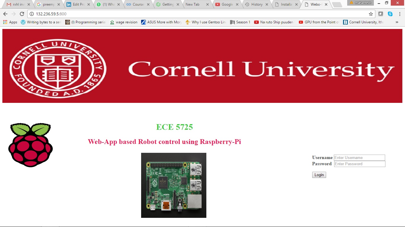
As soon as a user accesses BRB's IP address, he/she is presented with a login screen. The user can access the maneuver dashboard only after a successful login. New users can be added only by admins. The bot, upon receiving the commands from the user, calls appropriate functions to control the two servo motors to go forward/backward/left/right and vary its speed. The bot also has a camera module attached to it that provides a live video feed of the path.
Design & Testing
Overview
The design and testing process is broadly divided in three phases - Network, Web App and Motor Control. Before we dive deep in any of them, below is a block diagram [Fig. 1] that summarizes the complete design process.
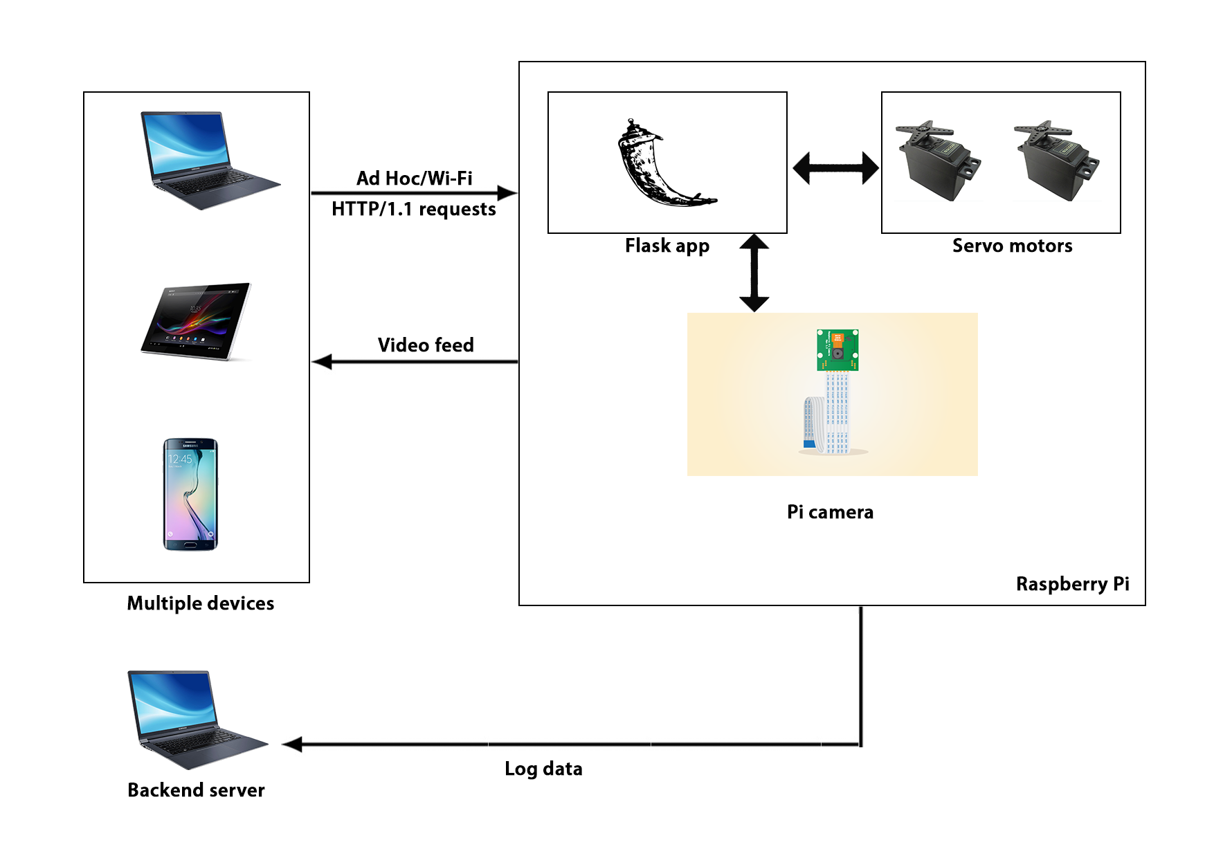
As shown above, Pi houses both the server (Flask) and the motor control module. Once the user successfully logs in, the server renders a HTML document containing a dashboard. The user can then login and send HTTP requests which Flask can parse to control the motors. The user can access the video feed on a different port. The backend server can be run on the same (or different device) to keep a log.
Network
To provide wireless capabilities to the bot, we used the Edimax Wi-Fi module [1]. We implemented two types of network connections for this project i.e. Ad Hoc and regular Wi-Fi. The main advantage of Ad Hoc is that it does not require any external Wi-Fi to connect to the client. The client can simply join the Ad Hoc and access bot controls. This is particularly useful when the user wants to take the bot outdoors where there is no Wi-Fi. The steps to configure an Ad Hoc network [2] on Pi are below.
First, open the network interfaces file for editing.
$ sudo nano /etc/network/interfacesNext, edit the file as follows.
auto loiface lo inet loopbackiface eth0 inet dhcpauto wlan0iface wlan0 inet staticaddress 192.168.1.1netmask 255.255.255.0wireless-channel 1wireless-essid RPiAdHocNetworkwireless-mode ad-hocNow, restart the wireless connection.
$ sudo ifdown wlan0$ sudo ifup wlan0At this point, we have configured the Pi to host an Ad Hoc network but to make other devices connect to it and communicate effectively, we need to install the DHCP server on it so that the Pi can assign IP addresses to its clients.
$ sudo apt-get update$ sudo apt-get install dhcp3-serverOnce the installation is done, we need to update the config file.
$ sudo nano /etc/dhcp/dhcpd.confUpdate it with the following.
ddns-update-style interim;default-lease-time 600;max-lease-time 7200;authoritative;log-facility local7;subnet 192.168.1.0 netmask 255.255.255.0 {range 192.168.1.5 192.168.1.150;}The Pi is now ready to communicate with the client. However, we observed that the Ad Hoc method worked successfully only with a PC and not any other platform. We were able to connect iOS and OS X devices to the Ad Hoc netowork hosted by the Pi but could not access the web application. To overcome this problem, we used both the Wi-Fi adapters available on the Pi. We configured wlan0 for hosting an Ad Hoc network and wlan1 as a regular client which would connect to an external Wi-Fi. So far, we have successfully set up our network and can move ahead to setting up our web application.
Web App
The layout of the web application is as follows.
- ../control.html
- ../login.html
- controller.py
- server.py
- run_test.py
controller.py is the main program that renders both the web pages. login.html is the first web page that gets loaded and checks for userID and password. Once authenticated, the next page loads which acts as a dashboard to control the bot. run_test.py contains the code for controlling motor by varying duty cycle. Due to this, we can keep our main program uncluttered and simply call run_test.py from controller.py. server.py is another script which was developed as an extension to this project. It basically logs all the details including users who logged in, the commands that they ran into a text file on a remote server.
For this project, we are using the Flask microframework because it is lightweight and does not require an external server such as Apache to be installed for running applications. Flask is easy to install.
$ pip install flask
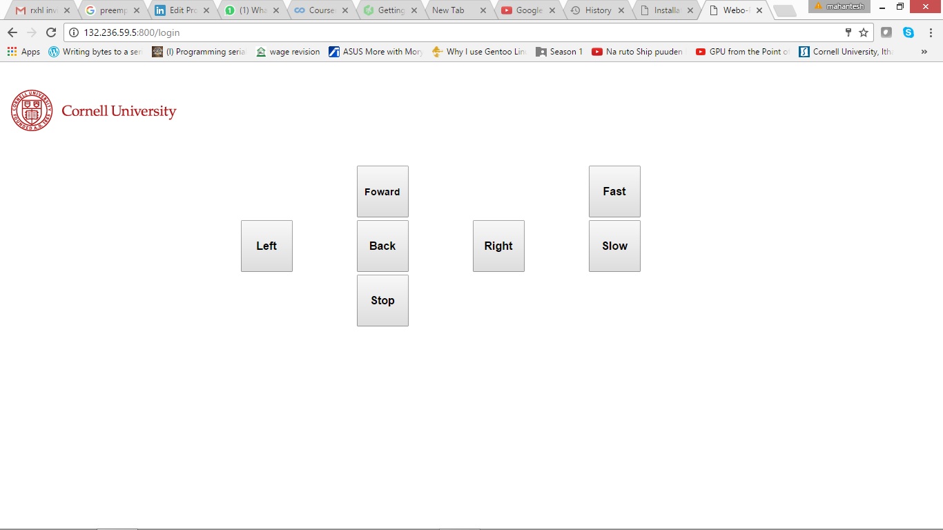
Then we wrote our Flask application to render HTML webpages upon request. The application stores userID and password pairs in a dictionary to authenticate users on login. Once the login is successful, the application renders another HTML page which contains a form having buttons corresponding to direction/speed control and sends it back to the server using POST. This page, rather a dashboard, is the primary interface to control the bot. It supports seven commands that can be sent to the bot.
- Forward
- Backward
- Right
- Left
- Fast
- Slow
The layout of login screen and controller screen are shown in Fig. 2a and 2b respectively.
Motor Control
The final part includes rigging up the bot chassis and interfacing the servos with the Pi. A regular servo motor is designed for 180 degrees swing i.e. 90 degrees to left of neutral position, and 90 degrees to right. Continuous Rotation (CR) servos are a modified version in which the shaft can rotate continuously by essentially removing the physical hard-stops. CR servos behave like compact DC gear motor with built in H-Bridge driver and can be controlled through a pulsed signal (like PWM).
For calibration, we send the servo a 1.5ms pulse refreshed every 20ms. Translating it into RPi, we use GPIO 19 to connect to the servo. The values for frequency and duty cycle are given below.
Frequency = 1/(1.5 + 20) = 46.511 Hz
Duty cycle = 1.5/(1.5 + 20) = 6.97%
As the length of the pulse decreases from 1.5ms to 1.3ms, the servo will gradually rotate faster in the clockwise direction [3], as shown in Fig. 3.
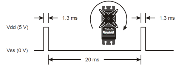
To express full speed clockwise rotation in terms of RPi.GPIO, we define our duty cycle as below.
Frequency = 1/(1.3 + 20) = 46.948 Hz
Duty cycle = 1.3/(1.3 + 20) = 6.10%
Similarly, as we increase the pulse width from 1.5ms to 1.7ms, the servo attains it maximum speed in the counter-clockwise direction and we get,
Frequency = 1/(1.7 + 20) = 46.082 Hz
Duty cycle = 1.7/(1.7 + 20) = 7.83%
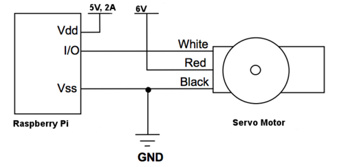
The safe way to connect servo motors to Raspberry Pi is to power the motors through a 6V battery or a regulated power supply of 6V. In this project, we are using 4 AA batteries to power the motors and a 5V portable rechargeable battery for Pi. The motors should not be connected to an unregulated power supply as the varying voltage can damage them. A generic connection diagram is shown in Fig. 4.
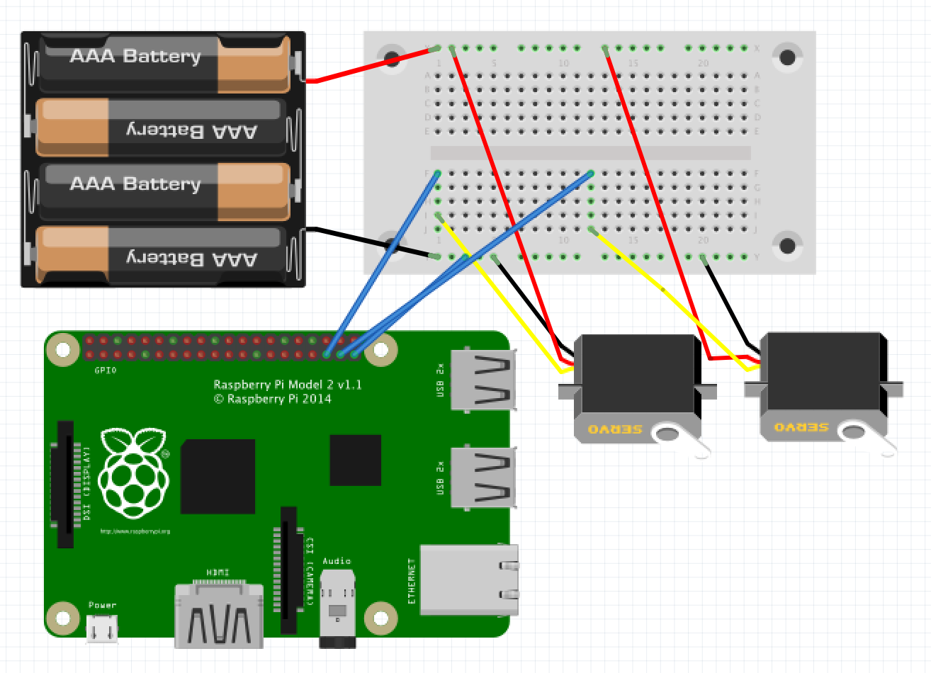
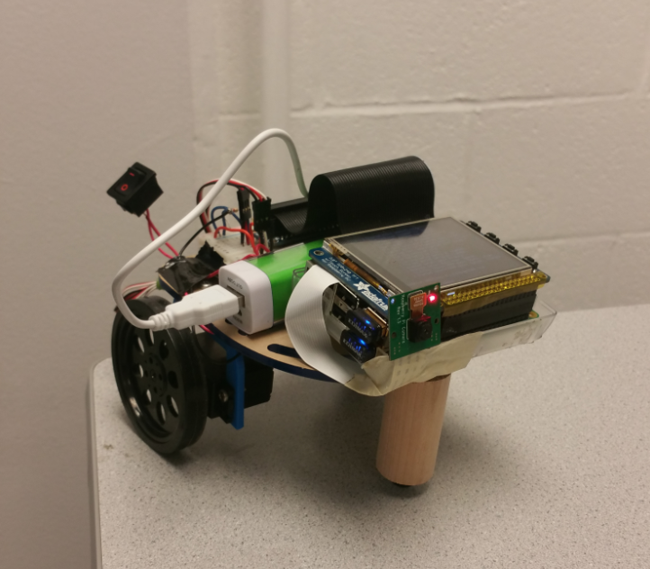
In this project, we are using two servos that are connected to the GPIO pins 19 and 26 as shown in Fig. 5. Connecting the camera module is simple. We are using the official Raspberry Pi camera module v1, just connect it to the CSI port on the Pi and make sure it is enabled in the Pi configuration utility. Once the setup is complete, the bot should look like as in Fig. 6.
Result & Conclusion
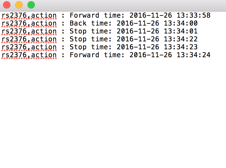
The primary goals of the project were achieved and the bot performed as expected. We were able to login and control the bot simultaneously from a PC (through Ad Hoc) and Android device (through Wi-Fi). We tested the bot at different locations to check its range. In absence of any obstacle (wall etc), the bot could be controlled for upto 100 meters. In presence of obstacles, the distance reduced to 15-20 meters. We also implemented an auto-stop function that would stop the Pi automatically if it does not receive any command from the user within 5 seconds. Additionally, we found out that the video feed's frame rate gets reduced over Wi-Fi as compared to that on the Ad Hoc network. The video feed screen and the backend server log are shown in Fig. 7 and 8 respectively.

A demo video of the project is shown below.
Future scope
- The bot can be used for home surveillance purposes. It can navigate through the house and repot any suspicious activity.
- The bot can be employed for search and rescue operations at locations where it is hard for a human to go.
Appendices
A. Code
Due to the sheer amount of code and its maintenance, the entire project repo can be found here.
B. How to run Big-Red-Bot
- Download the project repo on your Pi.
cd ~/../Big-Red-Bot$ sudo python controller.py- On your device, goto http://a.b.c.d:800, where a.b.c.d is the IP address of your Pi.
- For the video feed, goto http://a.b.c.d/webopi
- Enjoy!
C. Distribution of work
The initial hardware setup was done by both Mahantesh and Rahul. Then, Mahantesh developed the wireframe for the Flask app, then both of them worked on the login screen. Once that was completed, Mahantesh worked on making the controller screen while Rahul worked on setting up the Ad Hoc network. The Ad Hoc ran successfully with PC but not any other platform and this was the major roadblock for the project. While Mahantesh added more functions to the controller screen and the back end server, Rahul worked on overcoming the networking problem by installing another Wi-Fi adapter to make the bot accessible from both and Ad Hoc and regular Wi-Fi in parallel.
Furthermore, Mahantesh interfaced the camera module while Rahul started documenting the project. While Mahantesh worked on cost analysis and future scope, Rahul designed the HTML/CSS template. Finally, both of them edited the report for the final version.
D. Bill of material
| Item | Unit Price ($) | Quantity | Total Price ($) |
|---|---|---|---|
| Raspberry Pi 2 | 35.00 | 1 | 35.00 |
| Servo motor | 5.95 | 2 | 11.90 |
| Edimax Wi-Fi adapter | 7.99 | 1 | 7.99 |
| Half size breadboard | 5.00 | 1 | 5.00 |
| AA battery | 0.40 | 4 | 1.60 |
| RPi camera module | 19.95 | 1 | 19.95 |
| Total amount | 81.44 |
E. References
[1] Edimax Wi-Fi adapter specifications
[2] Configuring Ad Hoc network on Raspberry Pi
[3] Parallax Continuous Rotation Servo (#900-00008) Datasheet
Getting started with Flask
Web interface for RPi camera module
Requests: HTTP for Humans
Embedded OS - A Practical Approach textbook
Lecture slides
Team


Acknowledgement
We would like to acknowledge and thank Professor Joe Skovira for helping us throughout this project and for the wonderful class. We would also like to thank the fall 2016 TAs - Brandon, Jingyao and Jay for their support.