Objective top
The goal of this project is to develop a wireless gesture controlled robot using two Raspberry Pis (RPis) and an accelerometer. This project consists of four parts. First, for the controller, we attached an accelerometer to one RPi to detect gestures including basic orientation, tilt, single tap, and double tap. Second, we also attached a LCD display as user interface to adjust robot speed and motion history. Third, we developed wireless communication between two RPis through Wi-Fi and socket. Fourth, we controlled two motors of the robot using hardware PWM of the other RPi. Then, user can tilt or tap the controller to configure and change the motion of the robot remotely.
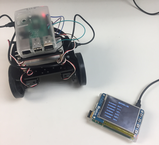
Photo of the robot and its controller
Demo Video
Introduction top
Touch screen, gesture, and voice control technologies grow up rapidly in recent years. They gradually replace the conventional control panel which has lots of buttons on it. We have thought about these different ways to achieve wireless robot control and decided to design a gesture controlled robot. Compared to voice recognition, gesture control is more accurate and requires less computational resource. We could detect gesture either using camera and image processing or using an accelerometer. Finally, we decided to use an accelerometer since robot controlling does not require complex gestures, it needs less computational resources and it is much cheaper than a camera. As a simple introduction, accelerometer is a device that measures proper acceleration. So, it can detect tilt in different orientations, single tap, double tap and free fall. These options are enough for our robot control which could move forward, backward, turn left, turn right at different speed. During the four-week final project period, we have successfully implemented all the objectives. Section 3 describes the design in detail. Section 4 shows our final project result. Section 5 is the conclusion and future work. The budget report and team member contribution can be found in Section 6.
Design and Testing top
The high-level block diagram and the picture of our design is shown below . In order to remotely control the robot with the controller, we have two RPis act as command sender and receiver respectively and communicate through WIFI using TCP. On the sender side, an accelerometer is connected to the RPi as the controller. The communication is implemented using 2-wire I2C for reading and writing the registers in accelerometer. The sender RPi is also connected with a TFT Screen for displaying the information while controlling the robot. For the receiver RPi, it connects with two servos to drive the wheels of the robot. The hardware PWM is used here to obtain different speeds and directions. Our detailed program implementation can be divided into four parts: accelerometer configuration, user interface, wireless communication, and wheel control. We discuss each of them following.
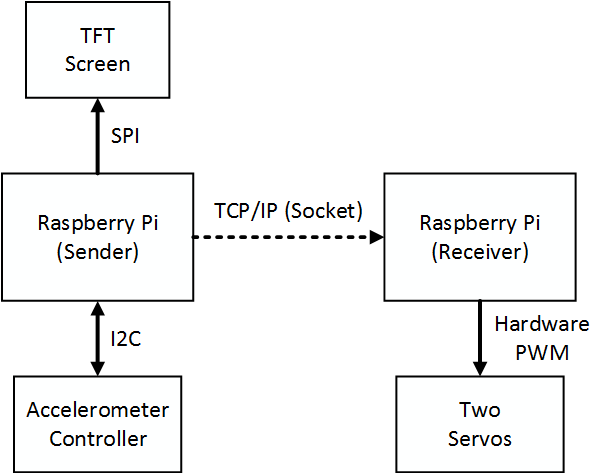
Diagram of gesture controlled robot system
Accelerometer Configuration
The accelerometer we used in our design is LIS3DH, which is a 3x3mm 3-axis accelerometer produced by STMicroelectronics. This accelerometer allows both I2C and SPI protocol for the communication and we decided to choose I2C because it requires fewer wires. Since the chip is tiny and thin enough, we hided the accelerometer under the TFT screen for a better appearance of our controller. Only four wires in total, which are VDD, GND, SCK, and SDA, are used for the connection of the accelerometer. This not only saves the space but make the potential extension possible. All the configuration and using of the accelerometer are through I2C protocol with reading and writing. We used the I2C library provided by Adafruit which is based on the SMbus of the RPi. Since all the registers in the accelerometer are 8 bits long and we do not need to read or write the adjacent registers continuously, only 8-bit read and 8-bit write are used in our design which is completely sufficient.
The software working flow of the LIS3DH is shown below. Firstly, the I2C bus is set up with the given address of the accelerometer. This step is done by importing the Adafruit I2C library and using the corresponding function. After the I2C is successfully set up, we can start the general initialization of the accelerometer by writing value to the relative registers, which includes the setting of output data rate (ODR), resolution, and g-range. Many of these settings requires to modify only one or several bits in the 8-bit register. Simply write to the register may change the original settings represented by other bits. To deal with this situation, we need to read the values for the corresponding registers, conduct a masked modification, and then write it back to the registers. The accelerometer can start operating after the general configuration is done. However, since we leverage the build-in engines in our designs, the orientation engine and single/double click engine are supposed to be turned on as well. Similar to the general configuration process, we write values to the related registers. For the orientation engine, the 4D mode is used instead of 6D mode since we do not care the detection on z axis. For single/double click engine, we need to determine the values of each parameters to obtain the best click performance. After all these are settled down, we keep reading the data from the interrupt register to see whether there is a click or tilt happens and send corresponding message to the robot.
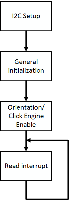
Accelerometer Program Working Flow
User Interface
On the controller side, a TFT screen is used for the information display while controlling the robot. To improve the user experience and make the robot more controllable. We built a user interface based on Pygame which mainly consists of three functions: running history, speed control, and pause. The running history is a log to show the previous motion that the users made. The speed control panel is for setting the speed level for each motion that the robot can make such as forward, backward, left turn, and right turn. Last, pause interface provides a sleep mode for the controller by disabling the functions when it’s idle.
The general software diagram is shown in below. We leveraged the FSM structure to build the user interface. When the program starts, the user interface shows the motion history by default. The max number of history slot is 12 and each slot hold the information of both motion type and the time it lasts. When a motion is launched by the user, it first appears on the screen in red color at the newest slot. After the motion is done, the time consequently appears next to the motion in second. This mechanism helps the user to keep tracking of what they have done. A double tap will trigger the switch to speed control mode. In this mode, the users are allowed to customize the speedo of the robot. Each motion, respectively, has three levels of speed that provides to the users. Front/back tilts can be used to select the type of motions and right/left tilts are for selecting the speed levels. Similarly, a double tap will make the user interface jump back to the motion history. Besides, we also designed a pause interface and a sleep mode to prevent the misoperations when the controller is idle. We use the single click engine in the accelerometer to implement this function. When a single tap is received which can be done by placing the controller on the table, the controller will enter the sleep mode after 2 seconds. If users make other operations within these two second, the controller will not enter the sleep but still keep tracking the motion from the user. After a pause screen shows up with the sleep mode, all the functions will be disabled which means the communication between the sender and the receiver will be cut. Only a single tap will wake the controller up and push it back into the normal mode. Both motion history and speed control interface are able to enter the pause mode.
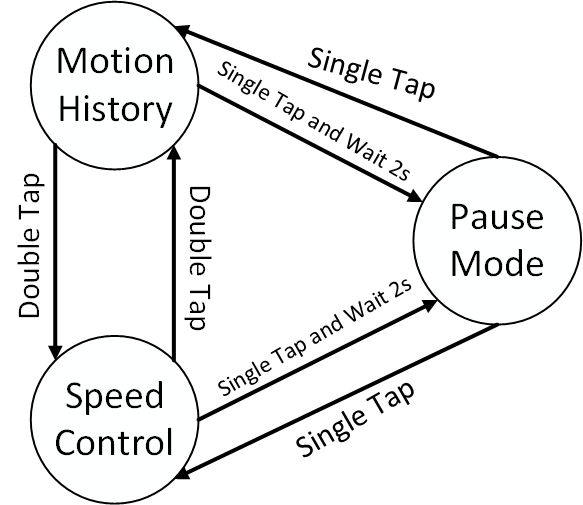
User Interface Program State Diagram
Wireless Communication
We used socket to implement a TCP protocol between two RPis and the message can be transferred through WI-FI. In our project proposal, we initially planned to use UDP communication instead of TCP but then we realized that TCP has the advantages of ensure the message in order and more reliable. We configured the controller as a client and the robot as a server since the client connects to the server through socket and sends requests or commands. The server will process the commands and take action according to each command correspondingly. In our case, the server does not need to sending data back to the client since we only need to send motion commands from the controller to the robot.
For the controller, it first needs the IP address and port number of the robot. The IP address of the robot can be found by ifconfig command after it connects to WI-FI successfully. The port number is randomly chosen. Next, we initiated a socket as TCP protocol with two arguments, API_NET refers to address from the internet IPv4 addresses, and SOCK_STREAM refers to delivery in order. Then, we can connect to the robot using the connect function of the socket with the IP address and the port number and send messages using the send function.
For the robot, in order to setting up connection with the controller, it needs to use the same port number as the controller specified. If leaving the IP address blank, it will automatically use the host IP address. Next, it creates a socket with the same configuration as the controller and set the socket to reuse the address since we found that without reusing, it will reserve the port even the connection broken. It binds the IP address and the port to its socket. Then, it listens on this port waiting for messages. We used the accept and recv functions with a receiving buffer size to collect the messages from the controller.
Wheel Control
We setup the servo and the RPi connection as shown below. We configured GPIO13 and GPIO18 to control two servos using hardware PWM. Compared to software PWM, hardware controlled PWM is much more stable. After setup, we first calibrated the servos. According to the instructions on the datasheet, the speed and the direction are determined by the duration of the high pulse in a range of 1.3ms – 1.7ms. When the high pulse is 1.3ms, the servo rotates in full speed in the clockwise direction. Likewise, a high pulse of 1.5ms and 1.7ms indicate the stop and the full speed in counterclockwise direction respectively, as shown below. In addition, an 20ms pause is required in between two pulses for smooth rotation. Therefore, we set the PWM frequency to 50Hz and duty cycle at 7.5% as fully stop. To run the wheels forward, we need to set the duty cycle in the range of 7.5% to 8.3% and to run the wheels backward, we need to set the duty cycle from 6.7% to 7.5% according to the description above. We used the 5V output pin of the RPi as power supply for the servos. While running the program, we calibrate the servos using screwdriver until they both fully stop at 7.5% duty cycle.
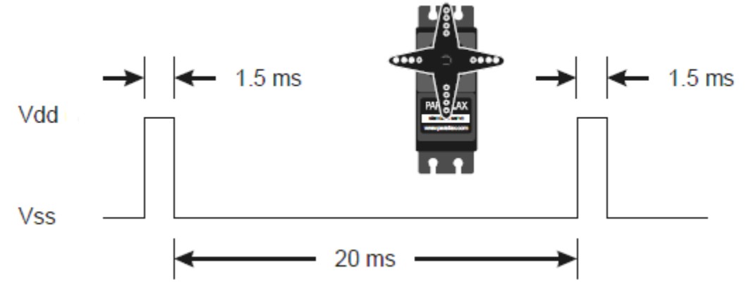
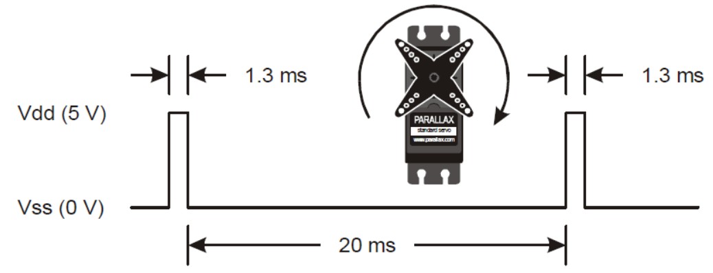
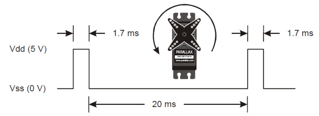
Servo PWM Timing Diagram
Retrieved From Parallax Continuous Rotation Servo
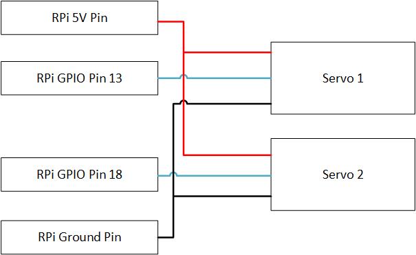
Servo RPi Connection Diagram
The main loop of the receiver first waiting for next command from the controller. After receiving motion command, the program decodes the command and calls wheel control function with the GPIO numbers connected to the servos, motion command and speed level. We set all the command length and the receiving buffer size be the same in order to achieve fast transfer. If the buffer size is longer than the message, sometime due to network delay, the consecutive messages will concatenate together. The commands are shown in the table below. At the end of the program, we need to close the socket connection, stop hardware PWM and clean up GPIO. The program handles keyboard interrupt as well.
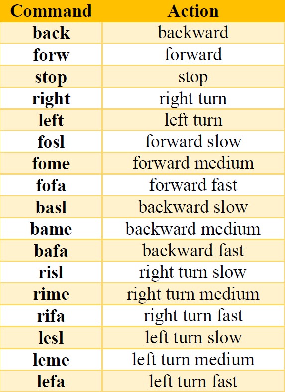
Message Command Mapping Table
Results top
For the accelerometer, the parameters used in our project is shown in the tables below. These values ware obtained by repeatedly testing and verifying. The goal is to make the controller sensitive without too much fault cases.
Accelerometer Parameter Configuration
The user interface we designed shows below. The goal here is to make a user-welcomed display and also fulfill all the necessary functions.
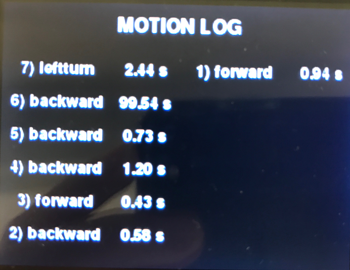
Motion Log Example
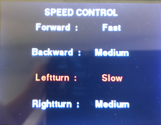
Speed Control Manual

Pause
The speed and duty cycle mappings are shown below. Three different speed levels were chosen for each wheel. The goal is to make different speeds distinguish from each other and within a reasonable range.
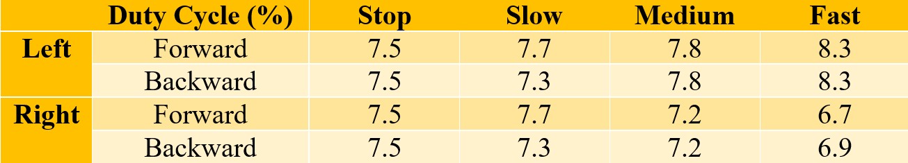
Duty Cycle Servo Speed Mapping Table
Conclusions and Future Work top
In this project, we have implemented a gesture controlled robot using two RPis, an accelerometer, a TFT display, two motors and a robot framework. What we had learned in previous labs got into use of our final project. For example, the PWM motor control, GPIO configuration and TFT display using the Pygame library from lab3. We also learned about wireless communication between two RPi using socket through WI-FI and attached external sensor, accelerometer to the RPi to build an embedded system. We did encounter some problems as designing our project. For instance, several times, the RPi was not able to connect to internet using WI-FI dongle and required to use ethernet. Since we did not attach a TFT display to the robot RPi, it is hard to debug internet connection problem. If there is delay in the network, the robot will not listen to the controller in a timely manner. Another problem we had was how to accurately detect double tap and single since double tap covers a single tap and the accelerometer is very sensitive. We have already solved most of the problems but the accuracy of the single tap and double tap could be improved. Right now, double tap is very sensitive to where the user taps. Another improvement could be finding other way rather than WI-FI to achieve wireless communication since connecting to the school network for short-distance communication is not efficient.
Appendices top
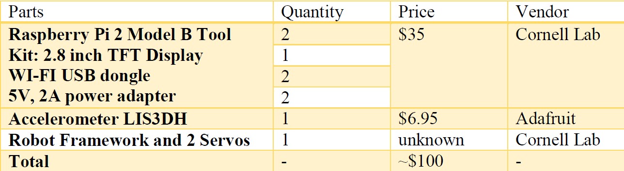
A. Budge Report
B. Team Member Contribution:
Mengcheng Qi: Assembled the robot; Designed the TCP communication; Designed wheel control; Built the hardware on the receiver’s side. Participated in the overall design test.
Wendian Jiang: Focused on the accelerometer configuration. Designed the user interface. Built up the hardware on the sender’s side. Participate in the overall design test.
C. Source Code:
Acknowledgements top
We would like to thank Professor Joseph Skovira for his nice and patience advice during the lab sections. Whenever we had difficulty or looked for parts, he provided help with anything that we needed. In addition, we would like to thank our TA Jingyao for always being available to answer our questions.