Hardware Design
Introduction
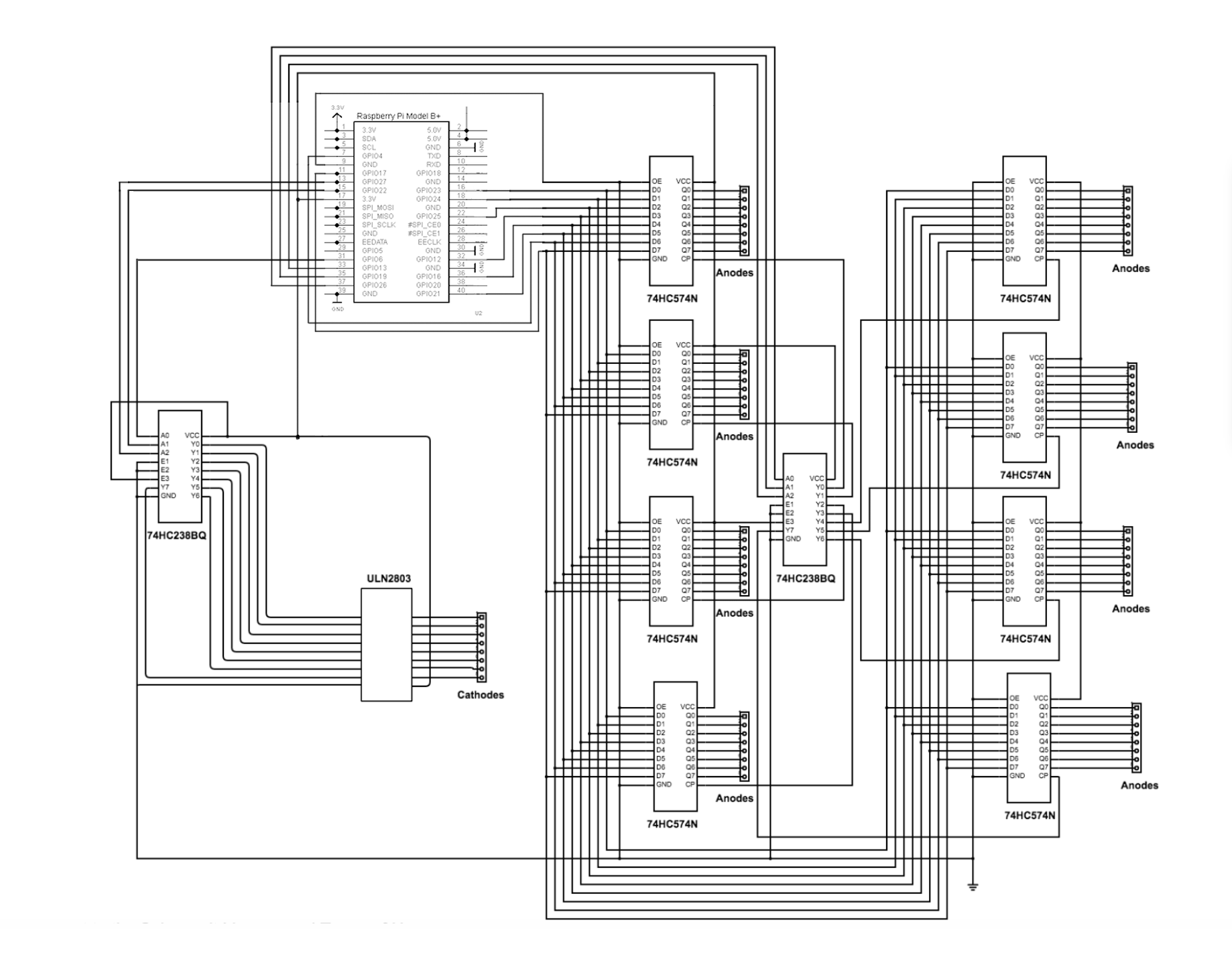
The LED cube contains 8 horizontal layers and 64 columns. The negative(cathode) legs of all LEDs on the same layer are soldered together, and all positive(anode) legs of all LEDs in a column are soldered together. So, each of the 8 layers and each of the 64 columns can be controlled individually. The natural way to manipulate the LED cube is to assign a pin to each LED. Unfortunately, we don’t have that 512 pins, so we have to find out another way to control the massive LEDs using poor number of GPIO pins we have on RPi. Making good use of an optical phenomenon called persistence of vision (POV) , that if you flash a led really fast, the image will stay on your retina for a little while after the led turns off, we are able to do achieve that using only 14 pins. We use 8 latches and 2 3-8decoders to do this job, that only requires 14 pins, which is absolutely viable.

Components
We use 8 latches, two 3-8 decoders and 1 ULN(Darlington array) to do the control work:
1. 8 latches are to update and store on-off status of the 64 columns;
2. 1 latch-select decoder is to select which of the eight latches is enabled so it updates and stores the data from the 8 data pins from the pi;
3. 1 layer-select decoder is to select which layer is enabled. When refreshing the cube, the 8 layers are lit up one by one in a very high frequency so that your eyes can’t tell the LEDs are flashing
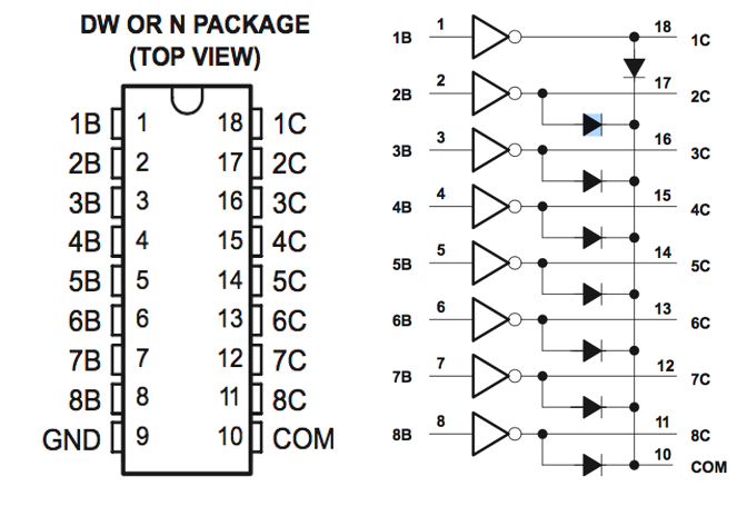
4. 1 ULN is used in cooperation with the layer-select decoder to sink current form each layer. The decoder would be destroyed if directly connected to the cathodes of 8 layers.
So, we totally use 8(data for latches) + 3(decoder for latch selection) + 3(decoder for layer selection) = 14 I/O pins to control 512 LEDs. It is quite incredible that 14 pins are sufficient to control 512 LEDs individually
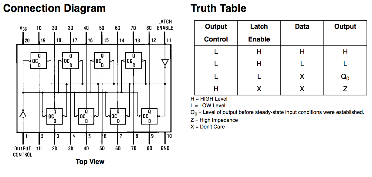
8 Latches (74HC573)
So, we totally use 8(data for latches) + 3(decoder for latch selection) + 3(decoder for layer selection) = 14 I/O pins to control 512 LEDs. It is quite incredible that 14 pins are sufficient to control 512 LEDs individually

3-to-8 Decoder (CD74HC238)
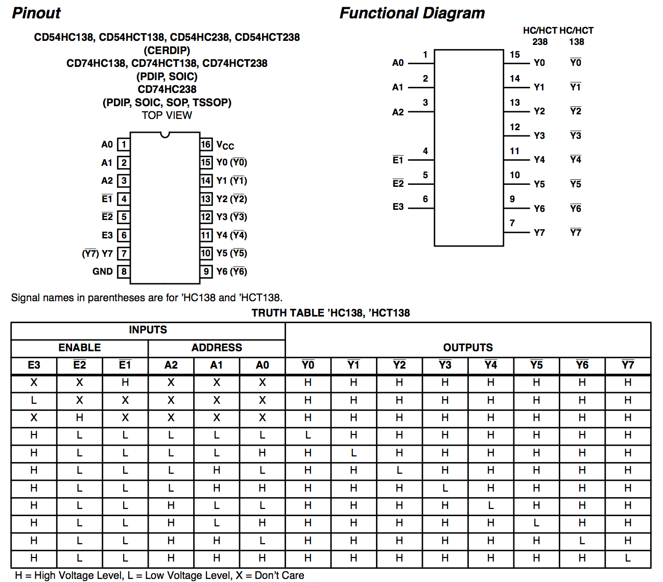
CD74HC238 is a 3-to-8 ldecoder, which decodes three binary weighted address inputs (A0, A1 and A2) to eight active high mutually exclusive outputs (Y0 to Y7). The function of CD74HC238 is to select horizontal layer and latch. The LED cube relies on the persistence of vision by flashing each layer really fast. Actually, we select a single layer at each clock cycle. So, one of the 3-to-8 decoder is to select the layer. After the layer is selected, the cube is flashed row by row, where a latch controls each row. So, the other decoder is to select which latch should output the pattern to the LED cube. The schematic and function table of CD74HC238 is shown below.

Darlington Transistor Arrays(ULN2803A)
