Wireless Mechanical Keyboard
Gautam Ramaswamy (grr37)
Sacheth Hegde (ssh88)
December 7, 2016
Objective
Keyboards are very ubiquitous in today's society, so our project was not directly addressing a problem in society. However, we were more curious on how to make wireless keyboards and the actual circuitry behind the keyboard itself. Additionally, we are very interested in mechanical keyboards, and were going to implement functional layers to allow for customizability. The component of wirelessly communicating with any device (such as a computer or phone) and the process of debouncing keys and keystrokes was where the Raspberry Pi would come in. Additionally, we made our keyboard "programmable", so that a user could SSH into the device and change any mappings.
Introduction
As briefly mentioned in the previous section, we decided to make a wireless mechanical keyboard. This keyboard is meant to work universally through the bluetooth HID interface (not only through an application where we can enter text). This means it can work as a keyboard on the phone or computer for example, and can work in any part of the user interface. There were two parts to the project. One involved the circuitry. We used a keyboard matrix to poll the keys and check which ones are being pressed, for example, and then read rows connected to these pins to narrow it to the exact one. We made a PCB to make the wiring for the keyboard to make routing easier, and made all the connections through the Raspberry Pi (as required for this project). The other part of the project involved the software, which was all accomplished on the Raspberry Pi with Python. The Pi was in charge of reading input pins for keystrokes, encoding the values properly with the correct codes, and sending them via bluetooth to the connected computer. The end application user device (such as the phone or keyboard) needs to manually make sure to connect to the device through bluetooth so the keyboard can send messages and keycodes to it. Finally, we created this project so it would be modular and not require unusual instructions or startup. Using the 'systemctl' and 'systemd' utilities on Unix, we made the keyboard program and bluetooth connection scripts automatically startup when the Raspberry Pi booted up, and restart in case there were any problems.
Design
Keyboard Hardware
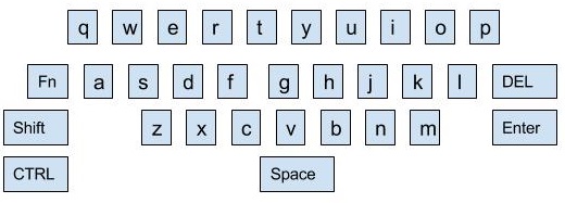
For our keyboard design, we decided to use a 32 key-layout, as this would have all the necessary keys but wouldn’t be too small to use. This key included all the regular letters (a-z) in the normal QWERTY layout, as well as 6 additional keys: Function, Shift, Ctrl, Space, Delete, and Enter. One may ask the question: what if the user wants to use numbers? This is where the function layer comes in. We have the special Function key, as mentioned previously, and pressing the Function key simultaneously with another key (such as q for example) leads to another key being pressed (in our design, it would be 1). This functional layer could be changed in our design, and this will be more thoroughly discussed in the software section. Our initial and final design for the keyboard layout is shown below.
In our initial design, for example, with the functional layer, the letters q to p would represent the numbers 0 to 9, and this would be accessed by pressing down the Function key to the left while holding down one of the letters.
Next, we needed to figure out the circuitry involved with the keyboard. In theory, it may be possible simple to hook up a pin to every single button on the keyboard, so that a signal can be triggered when it is pressed. However, this is not only very inefficient, but is impossible on most devices as you will require 32+ free pins, plus the pins we will be using for our bluetooth device. Therefore we need to use something known as the keyboard matrix to efficiently poll for keys being pressed. The picture shown below will help explain the concept.
Let’s use the example above as a 16-key keyboard. Using an input on every single button would require 16 input pins, which is doable, but once again, very inefficient. In the new implementation, as shown above, one would only require 4 inputs to the Raspberry Pi, each represented by the numberings along the rows. So to detect a keypress, the Pi would need to very quickly raise the voltage of one of the columns (labelled A-D). Then, if one of the keys was pressed at that point in time, the corresponding row would also become high voltage-wise, and this could be easily processed as an interrupt by the Raspberry Pi. The Raspberry Pi needs to quickly shift between making the voltages high on each column so that key presses will not be pressed, but this is not a massive issue as the Pi has the ability to work on a time scale in the milliseconds, and can very quickly cycle through the columns. This will be further detailed in the software section, but once a column is high (and the Raspberry Pi knows it is high), it can await any row voltage changes, and detect the keypress. As can be reasoned, this would then require 4 potential inputs from the Raspberry Pi to the keyboard, to provide voltages to the columns.
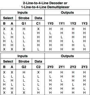
As mentioned, our design would use 32 keys, so we decided to have 8 columns and 4 rows. There are two things to note from this. First of all, in our keyboard layout shown earlier, some of the rows have up to 10 keys (which is more than 8 columns). This however, does not matter, as the column and row implementation is only important at the circuit level. On the actual schematic, we are able to move keys around, as long as they are mapped to the correct row/column on the circuit level. Second of all, with 8 columns, we would potentially need 8 inputs to the keyboard, which was something we didn’t necessarily want to do (for circuit simplicity sake). Therefore, we decided to use a decoder to do the job for us. We used the 74155N decoder chip, which actually contained two 4-output decoders, which led to 8 columns. Essentially, each output of the decoders would be mapped to a single column. We would then only require 3 inputs (disregarding ground and Vdd inputs) to the chip. One of the inputs would be used to chose one of the two decoders, and the other 2 inputs would be used to select one of the 4 options in each of the decoders. By option, we refer to a row being activated at that point in time. An example can be shown using the diagram below.
The figure is the truth table for the decoder. It is important to note, first of all, that it is an active-low based decoder, so the opposite actions need to be considered. The inputs A and B could be used to index within each specific decoder, which would lead to a single output being low (once again, this is the active state). The input G1 could always be tied to ground, so no input pin is required for this. The inputs C1 and C2 could be tied together as a single input, and this input choses which decoder to use. A high-logic value would use the first decoder, making all of the outputs of the other decoder high (inactive), for example.
So in the end, as described, we would need only 3 logical outputs from the Raspberry Pi to map each of the 8 columns, and only 4 logical inputs for each of the rows. The next step was to create the actual circuit. To simplify the routing and soldering, we decided to create a PCB through Altium’s software, and did so with the help of Jay Fetter. The basic schematic of the keyboard on Altium is shown below.
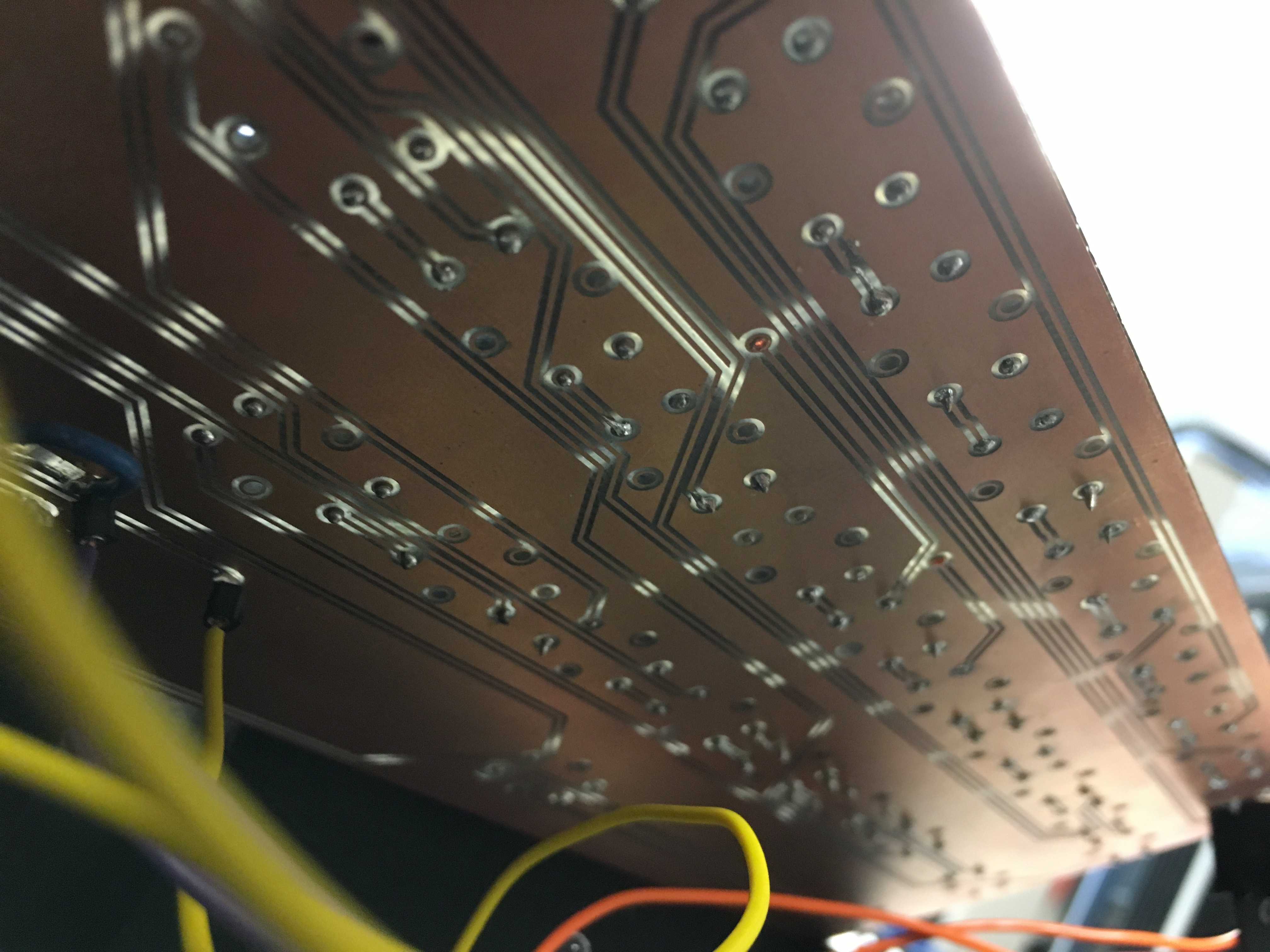
The four outputs (from each of the rows) can be seen on the top at the far left and right, and the decoder can be seen at the bottom right, with routes to each of the columns and inputs from the Raspberry Pi. With the help of Peter Slater, we were able to have this PCB created in only 2 hours at the MakerSpace PCB mill. Both sides of the PCB prior to full soldering can be shown below. Each side represents a different layer (the blue and red routes on the PCB footprint above represent the different layers).
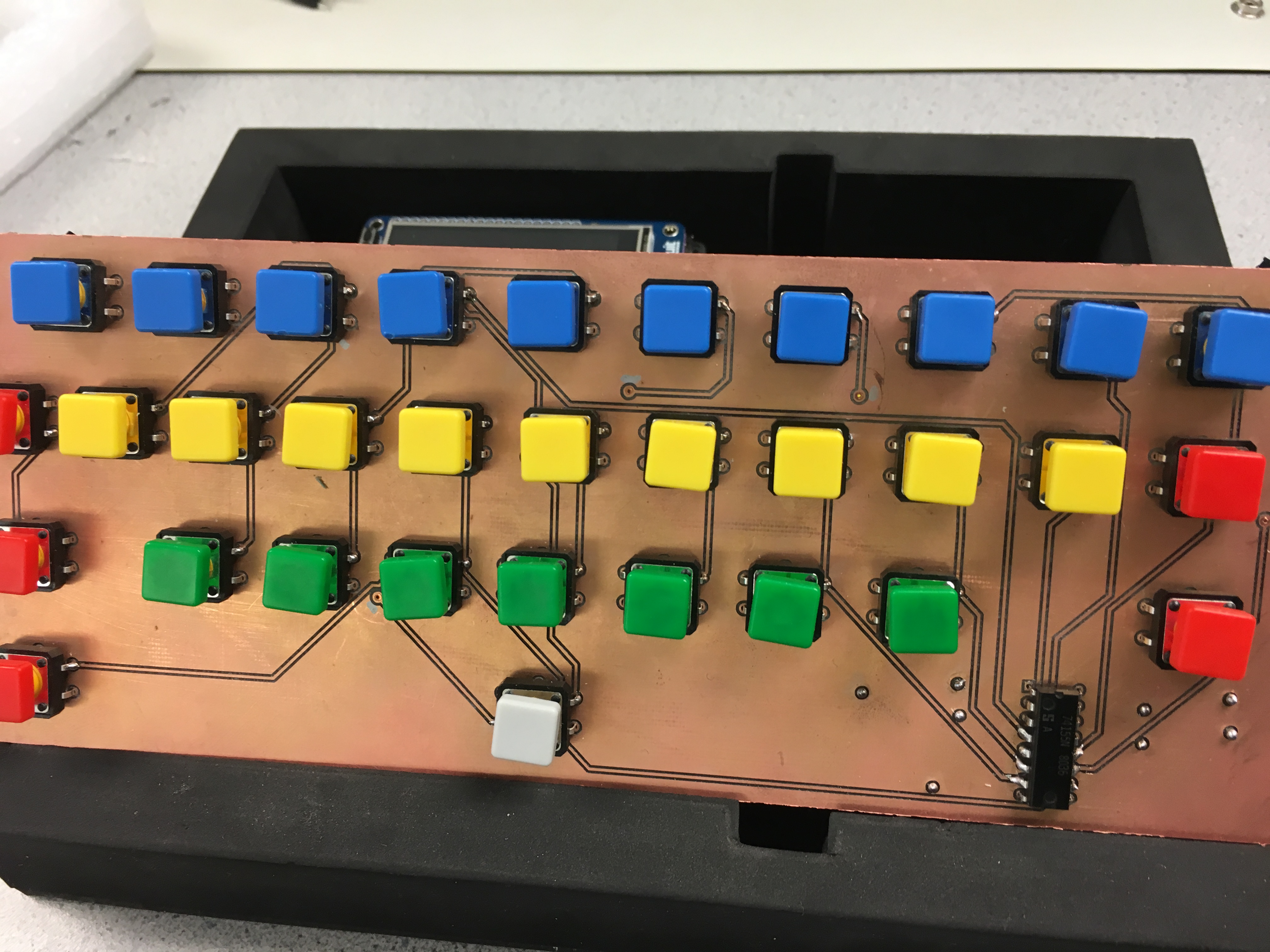
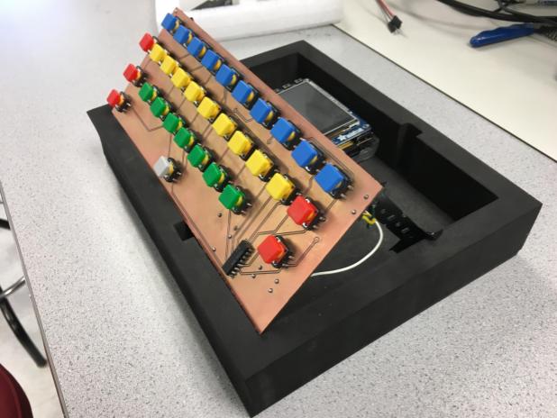
As can be seen, unlike traditionally PCBs, the entire surface is conductive, and the routes are made by cutting into the surface so the non-conductive material in between the two copper layers appears. This made soldering very difficult, as small bits of solder that ended up outside of the route would short the circuit. To test the integrity of the board, therefore, we needed to painfully test each solder point with a voltmeter and make sure the electrical components were properly soldered, and that there was no short. Additionally, the holes for the buttons were unfortunately a bit too small initially on the board, so we needed to tinker with the pins so the soldering would work. There were issues along the way, including soldered points which didn’t end up making contact with the board, shorted pins, and copper that got peeled off. In the end though, after a lot of soldering and hardware debugging, we were able to have a functional keyboard that worked with our test program. An example with all of the soldered buttons can be seen below.
As a final note, we added an LED behind the keyboard (that would illuminate from the back) that would shine whenever the function layer was activated. This is a feature in many keyboards, and helps the user know when they will be using the function layer or normal layer.
Bluetooth
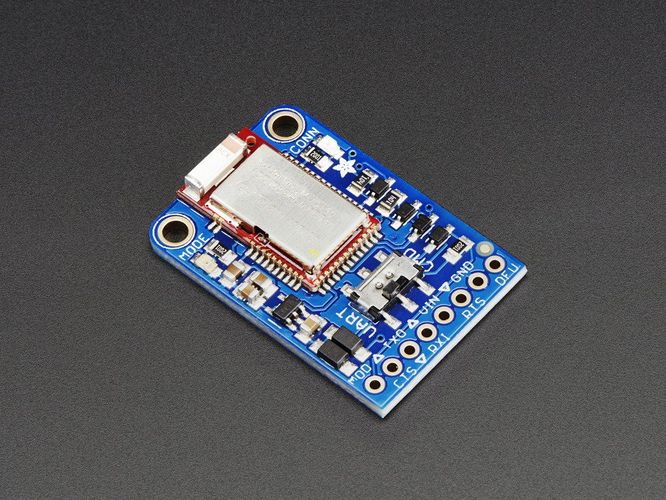
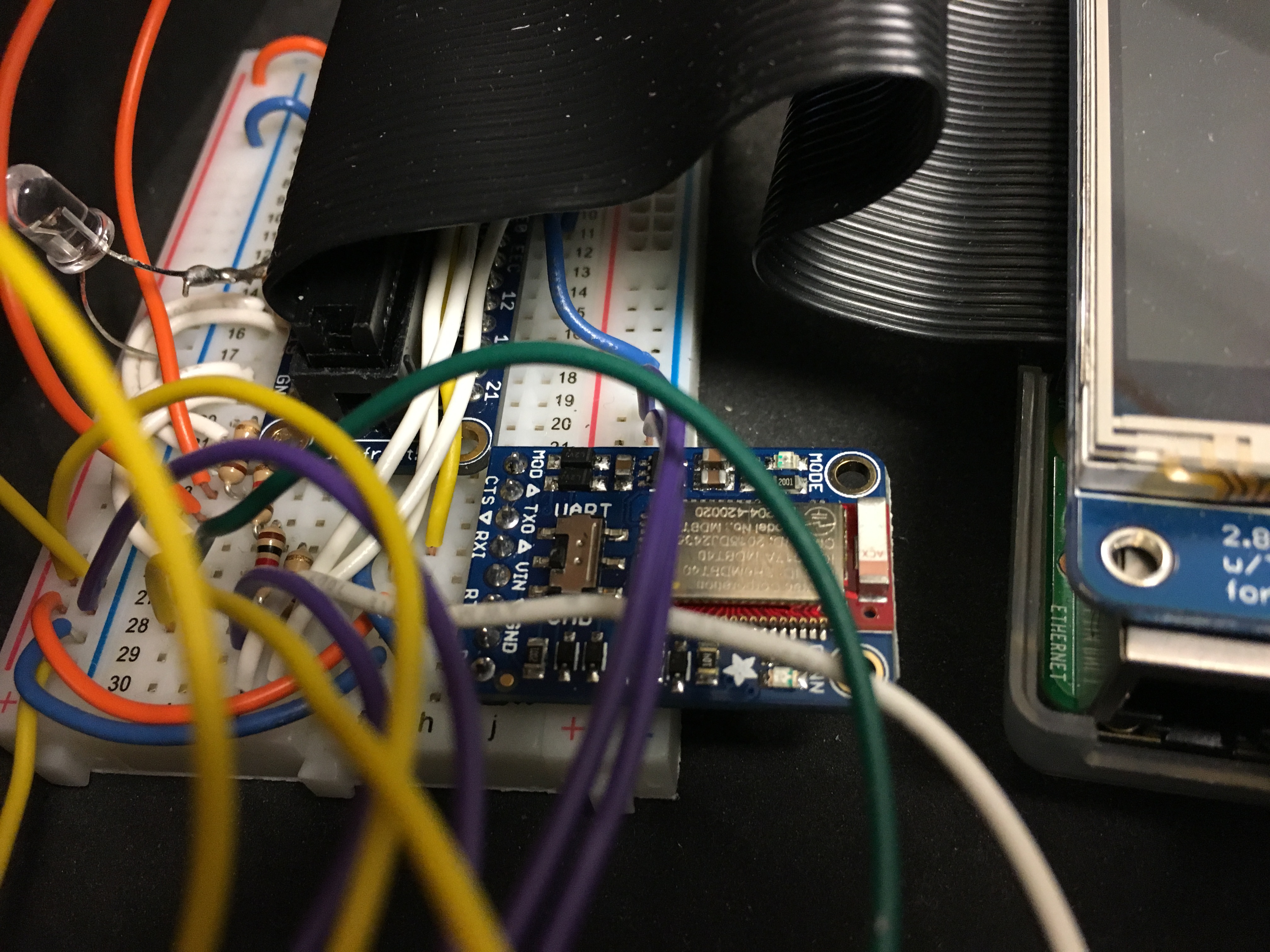
To use bluetooth, we used the Adafruit Bluefruit LE UART Friend chip. This chip uses the Bluetooth Low Energy specification to connect to Bluetooth capable devices. The chip supports two modes, UART mode and command mode. An image of the chip is below.
We started out by figuring out how to send data to the bluetooth chip from the PI. Since the chip uses UART, we could connect the Raspberry Pi’s TX pin to the chip’s RX pin, and the Pi’s RX pin to the chips TX pin. This meant that we could send between the Pi and the Bluefruit chip. To test whether we could send data through the bluetooth chip, we wrote short Python programs using the PySerial library to open up a serial UART port and connect it to the Raspberry Pi’s serial port. When the Bluetooth chip is paired with a device, such as a phone or computer. When in UART mode, the bluetooth chip would transmit the data it received from the Pi as UART data, which meant that to read it we needed to open up a UART terminal on the Android phone we were using to test. It was not possible to send data to other applications, which we wanted to do as we wanted the keyboard to be universally usable.
In order to make the bluetooth chip appear as a keyboard to other devices it is paired to, we needed to change from UART data mode, to command mode. In this mode, we can send commands via the serial port and the Bluetooth chip will send a response in return. These reponses could be an “OK” for when a valid command is sent, or “ERROR” if a bad command is sent. In addition, some commands also send additional information back to the Pi. The command we cared about was the “AT+BLEKEYBOARDEN” command. By setting this value to one by sending a “AT+BLEKEYBOARDEN=1” command to the chip using our program to send serial data to the chip, we could permanently enable the human interface device mode of the chip. This means that the chip will emulate a keyboard even upon reset.
To actually send data to the paired device, we needed to use another command. This command “AT+BLEKEYBOARD” would be able to send keyboard data to the paired device. If we were to send a command like “AT+BLEKEYBOARD=ECE5725\n” the string “ECE5725” would appear on the connected device with a newline following it. This command was also not quite what we wanted either as it would require an already functioning keyboard to send those keypresses and it would be impossible to send modifiers like CTRL, and ALT.
We finally found a suitable command that would allow us to send HID keycodes to the device. The command “AT+BLEKEYBOARDCODE” was a more complicated command. Each command requires a specific set of parameters, in the form of up to 8 bytes of data. The first byte of the data contains all of the modifiers being currently pressed. Each modifier is assigned a specific bit of the byte, and as such, there are 8 possible modifiers. These include, Left/Right CTRL, ALT, Shift, and Win. Thus, we can assign a full byte of modifiers by ORing all of the pressed modifier bits together. The next byte is always be a 0. The following 6 bytes of the command are each of the keys being pressed. This means up to 6 keys can be pressed at a time. As part of our implementation we only needed to handle one key at a time so we could ignore the last 5 bytes. Each key has its own HID key code and these can be found in section 7 of the following site. After sending the 3 necessary bytes for a modifier and keypress, there must be another command sent to signify a key release. This is simply two 0 bytes. Thus to send the letter “A” we would first send the command “AT+BLEKEYBOARDCODE=02-00-04” and then the command “AT+BLEKEYBOARDCODE=00-00”. Sending these would send an “A” to the paired device. Using this command, we could correctly send key presses to our phone or computer from the Raspberry Pi.
Keyboard Software
Our final keyboard code integrated the test bluetooth code that we had spent some time figuring out. The software needed to scan across the columns and check which input rows are being driven, which would let us know which key is currently being pressed. We used the RPi.GPIO library to handle the inputs and output pins of the Pi and used the serial library to interface with the bluetooth chip as described in the Bluetooth section. We used 3 output pins, one for each of the inputs we cared about for the decoder, namely the A, B, and C inputs. We also needed 4 input pins which correspond to the 4 rows of the keyboard. Each of these inputs is set up with a callback function on a falling edge to indicate that it has been activated. The fourth row event is also activated on a rising edge to indicate that a modifier has been released from being pressed.
In the main loop of our code, we poll each column by changing the A and B inputs. Since there are two decoders on the one chip, the C input determines which decoder we are activating. Thus, every 4 polls, we change C to check the other decoder, which corresponds to the last 4 columns. After each poll, the main thread sleeps for a short time (10ms) and then polls the next column. Each time we change one of the inputs a GPIO event could occur. To avoid false detections, we have a valid flag that is set after all changes have been made and then reset before we start making changes to the A, B, and C pins. The GPIO events make sure that that the valid flag is set first before doing anything else.
In order to debounce the buttons, we use a globally defined curr_time variable. Each time we enter the event handler we check what the difference is between that time and the time of the event handler occurring. If this time is less than 90ms then we accept it as a keypress and execute the rest of the handler and update the curr_time variable. This worked fairly well as opposed to using the bouncetime feature of the GPIO library, which was unreliable.
Once in the event handler, we would check which column was currently being polled. Each row has its own event handler so we knew exactly which key was being pressed. We had a mapping of (row, column) to key, where they key would be something like “q” or “f”. Thus, it was easy to figure out the exact key being pressed. The event handler would then start up a thread that would simply send serial data to the bluetooth chip. We decided to start threads so that the main thread would not get blocked by any serial transmissions.
To handle pressed keys, the modifiers, we had global variables referring to each modifier, such as shift and control. When they are pressed we set those variables to True. Each polling loop we check and see whether they are still pressed and if not we reset their variables back to false. In addition, we turned on an LED using PWM and a full duty cycle so that it is always on, to indicate that the user is in function mode. The threads sending the serial information will use the globals to determine which modifier byte to send to the Bluetooth chip.
In order for the program to know what the corresponding HID keycode was for every key pressed, we used JSON files to store the necessary information. They are an easy way to store data and bring in data into the Python program. Upon startup the Python program will read the JSON file containing all of the keycode mappings and load them into a dictionary. When we want to send a keypress, we simply index into that dictionary and build up the command using the correct keycode, as described in the Bluetooth section.
Since our keyboard only had 32 keys, we had to have multiple layers as a part of the functionality of our keyboard. This layer would be hidden behind a function key and would have separate mappings. We also decided to use JSON for these layers. The JSON file has two layers, the default layer (layer0) and the function layer (layer1). When the function key is pressed, the keyboard program switches to use the layer1 dictionary instead of the layer0 dictionary. Since both are keyed with the base keys (“q”, “w”, “e”, etc.), their values are what each layer actually maps to. Thus, it is easy to edit the JSON file and customize the positions of the keys. This makes the keyboard very user friendly.
Since all of the dictionaries are brought up on startup, we needed a script to restart the program and thus bring in all the dictionaries from their respective JSON files. We included a script called ‘edit_mappings’ which was globally available that opened the JSON file with a text editor, and allowed the user to change the file. As mentioned, it automatically restarted the running keyboard program so the new mappings would be applied.
Finally, we wanted to make the keyboard more “embedded” in nature, without requiring programs to manually run. We therefore used the ‘systemd’ utility within Unix, which allowed us to create a keyboard service that automatically ran at startup. With this, we were able to ensure that the script automatically ran as soon as power began (without requiring login), and if any issue were to happen with the process, Unix would automatically restart it. This simply required registering the command with a service on ‘systemd’.
Results
As mentioned earlier, our keyboard did work as expected, wirelessly, and to any end user device such as a computer or a phone. All of the keys worked as expected, with combinations such as SHIFTS, and modifier keys functioning. Additionally, our function layer worked as expected, and with the help of our global script, we made it very easy to change the mappings as the user deemed fit. The use of the ‘systemd’ utility also allowed the keyboard to work as soon as the Raspberry Pi was powered up.
A few pictures of our final device can be shown below. As described, it is completely wireless and is powered by a USB battery pack.
One thing to note is that the keyboard is mounted diagonally. This does actually make it easier to type, but admittedly, this is not the full reason why it appears as such. Because of the fragile soldering, we believe there is weak wiring or soldering on the board, and discovered that if the angle with the table is too small, the keyboard would stop working. Unfortunately, we weren’t able to debug this issue fully, but we did find out that when the keyboard was mounted as shown, it worked well.
The debouncing on the keyboard was also fairly accurate. Of course, when typing extremely rapidly (which is difficult with the use of the buttons), a few keystrokes may possibly be lost, but we were not able to see this issue after manually debouncing the keys and optimizing the polling time between all of the columns.
Conclusion
As alluded to within results section, we believe our project progressed and worked as expected. This included the physical keyboard along with the bluetooth communication. In the end, it has the ability to work as a fully functional keyboard, though obviously it is less refined and robust. However, we were able to make headway with the circuit side of interaction with the Pi (involving the keyboard matrix), as well as the software involved in transforming actions with key codes and transmitting data serially. The usability of the keyboard is ultimately what matters though, and we believe it may have been useful to use better buttons (which again, will be more expensive), and improving the user interface and compactness of the keyboard. Overall though, we did see all the different factors that go into making a basic keyboard. Because the keyboard is probably one of the most used tools by humans, it is extremely important that it is easy to use, robust, and doesn’t transmit incorrect data, and there are tradeoffs/optimizations that can be made on the hardware and software side for all of these points.
Future Work
With regards to future work, there are definitely a few things we could do to improve the device:
- Improve the aesthetics. Right now, the project does not look bad, but it uses buttons not meant for typing, and has the decoder and routes on the board in view. In the future, we could definitely improve the buttons (though real keycaps get very expensive) and make it more self contained in a box.
- Figure out the issue with angles of usage. This is something that we spent hours trying to fix, but if we did have more time, we could figure out what lose connection there possibly was in the project, so the user could use it in any configuration.
- Add in diodes to prevent masking/ghosting. Earlier in the project, we discussed adding diodes to prevent phenomas known as ghosting or masking. The way the circuit works, it is actually possible for a key to incorrectly be detected as being pressed if multiple keys are pressed simultaneously. This occurs because current can flow backwards through the switches, go through a switch that isn’t being pressed, and cause an invalid signal. The solution for this is to actually add a diode to every single key on the keyboard to prevent the backwards currently. We ultimately decided against this because of the lack of usage on our keyboard and complexity with soldering, but definitely should be done if this were to be a full-fledged keyboard.
Code Appendix
Member Contributions
Gautam Ramaswamy: Bluetooth code, keyboard code, some hardware debugging
Sacheth Hegde: Circuit and PCB design, Soldering, Hardware debugging, and keyboard code
Parts List
| Part | Vendor | Quantity | Description | Total |
|---|---|---|---|---|
| Raspberry Pi | Lab | 1 | Used for running the program | $35.00 |
| Tactile Pushbutton | Adafruit | 4 | Used for keyboard keys | $23.80 |
| Bluefruit LE | Adafruit | 1 | Used to communicate between RPi and BT device | $17.50 |
| Keyboard PCB | Maker Lab | 1 | Used to house buttons and decoder for circuit | $0.00 |
| 74155N Decoder | Lab | 1 | Used to power columns of keyboard matrix | $0.00 |
| Total | $76.30 |
Contact
Gautam Ramaswamy (grr37@cornell.edu)
Sacheth Hegde (ssh88@cornell.edu)
